Toshiba R410A Installation Manual
Hide thumbs
Also See for R410A:
- Service manual (228 pages) ,
- Quick reference (95 pages) ,
- Service manual (88 pages)
Table of Contents
Advertisement
Quick Links
Advertisement
Table of Contents

Related Manuals for Toshiba R410A


Summary of Contents for Toshiba R410A
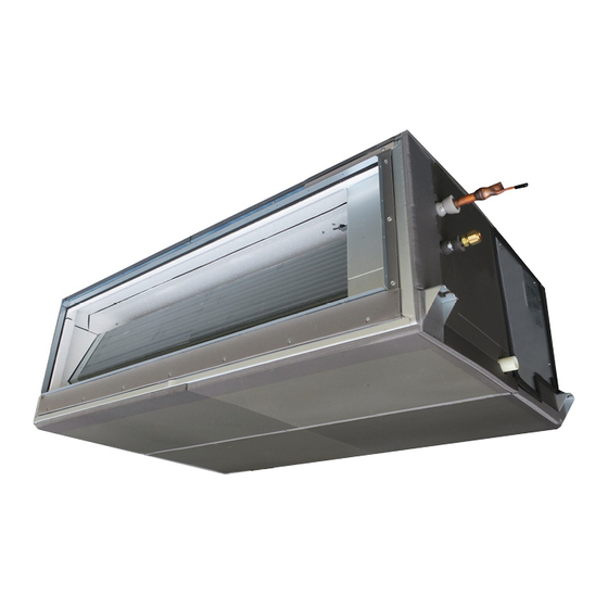
- Page 1 AIR CONDITIONER (MULTI TYPE) R410A Installation Manual For commercial use Indoor Unit Model name: Fresh Air Intake Indoor Unit Model with drain pump MMD-UP0721HFP-E MMD-UP0961HFP-E MMD-UP1121HFP-E MMD-UP1281HFP-E “Fresh Air Intake 12 HP and 14 HP applicable for SMMS-u series only”...
-
Page 2: Table Of Contents
Toshiba Carrier Corporation or, alternatively, he or she has been 11 Test run ..............26 instructed in such matters by an individual or individuals who have been trained and is thus thoroughly Qualified service... - Page 3 Warning indications on the air conditioner unit Definition of Protective Gear When the air conditioner is to be transported, installed, maintained, repaired or removed, wear protective gloves and ‘safety’ work clothing. Warning indication Description In addition to such normal protective gear, wear the protective gear described below when undertaking the special work detailed in the following table.
-
Page 4: Precautions For Safety
OFF position. • The refrigerant used by this air conditioner is the R410A. Otherwise, electric shocks may result. • The air conditioner must be transported in stable condition. - Page 5 • Do not move or repair any unit by yourself. There is high voltage • Follow the instructions in the Installation Manual to install the air inside the unit. You may get electric shock when removing the conditioner. Failure to follow these instructions may cause the cover and main unit.
- Page 6 – 5 – • After the installation work, confi rm that refrigerant gas does • Install a circuit breaker that meets the specifi cations in the not leak. If refrigerant gas leaks into the room and fl ows near installation manual and the stipulations in the local regulations a fi...
- Page 7 • For connecting pipes, use new and clean piping designed for allowed to relocate the air conditioner. It is dangerous for the air R410A, and please care so that water or dust does not enter. conditioner to be relocated by an unqualifi ed individual since a To Disconnect the Appliance from Main Power Supply.
-
Page 8: Accessory Parts
– 7 – Accessory parts System control of fresh air intake unit Accessory parts System able to be combined The fresh air intake unit is connectable to SMMS (Super Modular Multi system series). Part name Q’ty Shape Usage However this is not connectable to SHRM (Super Heat Recovery Multi system series), and MiNi-SMMS (MCY-**) series. -
Page 9: Selection Of Installation Place
Installation under atmosphere of the high humidity Selection of installation place Although it has been confirmed that no trouble occurs on the unit, there is a fear of drip of the water if operation Avoid installing in the following places under high humidity condition continues. -
Page 10: Installation
– 9 – Installation space Installation (Unit: mm) Reserve sufficient space required for installation or service work. CAUTION Strictly comply with the following rules to prevent damage of the indoor units and human injury. Do not put a heavy article on the indoor unit or let a person get on it. (Even units are packaged) Carry in the indoor unit as it is packaged if possible. - Page 11 Installation of hanging bolt Installation of indoor unit REQUIREMENT Removing the cardboard for transportation Consider the piping / wiring after the unit is hung to Treatment of ceiling determine the location of the indoor unit installation The ceiling differs according to structure of building. Make sure to remove the protection cardboard for transportation that is inserted in the gap between the top and orientation.
-
Page 12: Drain Piping
– 11 – Connecting drain pipe Drain piping Insert flexible drain hose into upper drain pipe of main unit as far as it will go. CAUTION Fix it with hose band. Following the Installation Manual, perform the drain piping work so that water is properly drained. REQUIREMENT Apply a heat insulation so as not to cause a dew condensation. - Page 13 Check the draining Heat insulating process In the test run, check that water drain is properly performed and water does not leak from the connecting part of As shown in the figure, cover the flexible hose and hose band with the attached heat insulator up to the bottom the pipes.
-
Page 14: Duct Design
– 13 – Flange arrangement Duct design Referring to the following dimensions, manufacture duct at the local site. CAUTION <Air outlet> Be sure to apply heat insulation to the duct to prevent dewy condition. 1430 (Unit external dimension) If there is an incomplete duct work, the water leakage into the room may happen. REQUIREMENT In order to prevent short circuits, design the duct work so that the intake and discharge openings are not adjacent to each other. - Page 15 <Example of construction> High-efficiency filter (Sold separately) Long life prefilter (Sold separately) Air supply Air supply duct *1 flange *1 Air intake flange *1 Heat insulator *1 Air intake duct Descending inclination (Sold separately) Canvas duct *1 Hood Product main unit Filter chamber Canvas duct *1 Heat insulator *1...
- Page 16 – 15 – External processor PQ MMD-UP0721HFP-E 50Pa 75Pa 100Pa 125Pa Standard air volume : 1680 (m³/h) Standard air volume : 1680 (m³/h) Standard air volume : 1680 (m³/h) Standard air volume : 1680 (m³/h) Rapid Strong+ strong Weak + Weak 1100 1300...
- Page 17 External processor PQ MMD-UP0961HFP-E 50Pa 75Pa 100Pa 125Pa Standard air volume : 2100 (m³/h) Standard air volume : 2100 (m³/h) Standard air volume : 2100 (m³/h) Standard air volume : 2100 (m³/h) Rapid Strong+ strong Weak + Weak 1200 1400 1600 1800 2000...
- Page 18 – 17 – External processor PQ MMD-UP1121HFP-E 50Pa 75Pa 100Pa 125Pa Standard air volume : 2520 (m³/h) Standard air volume : 2520 (m³/h) Standard air volume : 2520 (m³/h) Standard air volume : 2520 (m³/h) Rapid Strong+ strong Weak + Weak 1400 1800...
- Page 19 External processor PQ MMD-UP1281HFP-E 50Pa 75Pa 100Pa 125Pa Standard air volume : 3060 (m³/h) Standard air volume : 3060 (m³/h) Standard air volume : 3060 (m³/h) Standard air volume : 3060 (m³/h) Rapid Strong+ strong Weak + Weak 1700 2100 2500 2900 3300...
-
Page 20: Refrigerant Piping
Remove the all 6.35, 9.52 and 12.7 Wall thickness 0.8 mm or more brazed part. As the flaring sizes of R410A differ from those of q Tightening torque of fl are pipe connections 15.88,wall thickness 1.0 mm or more. refrigerant R22, the flare tools newly manufactured Incorrect connections may cause not only a gas leak, for R410A are recommended. -
Page 21: Electrical Connection
Airtight test / Air purge, etc. Electrical connection For air tightness test, vacuum drying and adding refrigerant, refer to the Installation Manual attached to WARNING the outdoor unit. Use the specified wires for wiring connect the terminals. Securely fix them to prevent external forces applied to the terminals from affecting the terminals. - Page 22 – 21 – Power supply wire and communication wires specifications <In the case of combining with outdoor units of Super Modular Multi System u series (SMMS-u)> Uv line and Uc line (L2, L3, L4) Wire size : 1.0 to 1.5 mm² (Up to 1000 m) Power supply wire and communication wires are locally procured.
- Page 23 Remote controller wiring <In the case of combining with outdoor units other than Super Modular Multi System u series (SMMS-u)> Control wiring between indoor units, and outdoor unit (L2, L3) 2-core with non-polarity wire is used for the remote controller wiring and group remote controllers wiring. (2-core shield wire, non-polarity) 1.25 mm²...
- Page 24 – 23 – Wiring between indoor unit and outdoor units NOTE A wiring diagram below is an example for connection to SMMS-u series. For connecting to other outdoor unit series, refer to the Installation Manual attached to the outdoor unit to be connected. q Wiring example Outdoor Power supply Outdoor Power supply...
- Page 25 Wire connection Remote controller wiring Strip off approx. 9 mm the wire to be connected. REQUIREMENT Connect the wires matching the terminal numbers. Incorrect connection causes a trouble. Wiring diagram Pass the wires through the bushing of wire connection holes of the indoor unit. Keep a margin (Approx.
-
Page 26: Applicable Controls
– 25 – Applicable controls Set data External static pressure Push OFF timer button. By doing so, the setup is completed. 0000 100 Pa Factory default To change other settings of the selected indoor 0001 50 Pa — REQUIREMENT unit, repeat from Procedure 0002 75 Pa —... -
Page 27: Test Run
All Fresh Air Intake Unit Group control Test run connection setting (Fresh Air Intake Indoor Unit) Other than Super Modular Multi System u series Before test run (SMMS-e or SMMS-7) The Fresh Air Intake unit and indoor unit for air conditioner cannot be connected as a group control. -
Page 28: Maintenance
– 27 – Maintenance Wired remote controller Periodic Maintenance For environmental conservation, it is strongly recommended that the indoor and outdoor units of the air conditioner Be sure to stop the air conditioner before making in use be cleaned and maintained regularly to ensure efficient operation of the air conditioner. When the air settings. -
Page 29: Troubleshooting
Troubleshooting Confi rmation and check If a problem occurs with the air conditioner, the OFF timer indicator alternately shows the check code and the indoor Unit No. in which the problem occurred. Check code The indoor Unit No. in which the problem occurred. - Page 30 – 29 – Check method On the wired remote controller, central control remote controller and the interface P.C. board of the outdoor unit (I/F), a check display LCD (Remote controller) or 7-segment display (on the outdoor interface P.C. board) to display the operation is provided.
- Page 31 Check code Wireless remote controller Outdoor unit 7-segment display Sensor block display of receiving unit Check code name Judging device Wired remote controller display Auxiliary code Operation Timer Ready Flash 01: TE1 sensor 02: TE2 sensor TE1,TE2 or TE3 sensor trouble 03: TE3 sensor 01: TL1 sensor 02: TL2 sensor...
- Page 32 – 31 – Check code Wireless remote controller Outdoor unit 7-segment display Sensor block display of receiving unit Check code name Judging device Wired remote controller display Auxiliary code Operation Timer Ready Flash ─ Model mismatch of indoor and outdoor unit ─...
- Page 33 Check code Wireless remote controller Outdoor unit 7-segment display Sensor block display of receiving unit Check code name Judging device Wired remote controller display Auxiliary code Operation Timer Ready Flash 01: Comp. 1 side 02: Comp. 2 side IPM short protection trouble Inverter 03: Comp.
-
Page 34: Specifications
Declaration of Conformity Sound pressure level (dBA) Model Weight (kg) Cooling Heating Manufacturer: Toshiba Carrier (Thailand) Co., Ltd. 144 / 9 Moo 5, Bangkadi Industrial Park, Tivanon Road, Tambol Bangkadi, MMD-UP0721HFP-E Amphur Muang, Pathumthani 12000, Thailand MMD-UP0961HFP-E MMD-UP1121HFP-E TCF holder: TOSHIBA CARRIER EUROPE S.A.S... - Page 35 1) No partition (shaded portion) The refrigerant R410A which is used in the air conditioner is safe, without the toxicity or combustibility of ammonia, and is not restricted by laws to be imposed which protect the ozone layer. However, since it contains more than air, it poses the risk of suffocation if its concentration should rise excessively.
- Page 36 – 35 – 69-EN 70-EN...
- Page 37 144 / 9 Moo 5, Bangkadi Industrial Park, Tivanon Road, Tambol Bangkadi, Amphur Muang, Pathumthani 12000, Thailand 1116950185...