Toshiba R410A Service Manual
Super heat recovery multi system
Hide thumbs
Also See for R410A:
- Service manual (109 pages) ,
- Quick reference (95 pages) ,
- Installation manual (37 pages)
Table of Contents
Advertisement
SERVICE MANUAL
The indoor units in the Super Heat Recovery Multi System are common to those used in the Super Modular Multi
System air conditioner. Therefore refer to the service manuals A03-009, A03-010, and A03-011 separately issued.
Heat Recovery Type
Indoor Unit
4-way Air Discharge Cassette Type
MMU-AP0091H, AP0121H, AP0151H,
MMU-AP0181H, AP0241H, AP0271H,
MMU-AP0301H, AP0361H, AP0481H
MMU-AP0561H
2-way Air Discharge Cassette Type
MMU-AP0071WH, AP0091WH, AP0121WH,
MMU-AP0151WH, AP0181WH, AP0241WH,
MMU-AP0271WH, AP0301WH, AP0481WH*
1-way Air Discharge Cassette Type
MMU-AP0071YH, AP0091YH, AP0121YH,
MMU-AP0151SH, AP0181SH, AP0241SH,
MMU-AP0152SH, AP0182SH, AP0242SH
Concealed Duct Standard Type
MMD-AP0071BH, AP0091BH, AP0121BH, AP0151BH,
MMD-AP0181BH, AP0241BH, AP0271BH, AP0301BH,
MMD-AP0361BH, AP0481BH, AP0561BH
Concealed Duct High Static Pressure Type
MMD-AP0181H, AP0241H, AP0271H,
MMD-AP0361H, AP0481H
Slim Duct Type
MMD-AP0071SPH, AP0091SPH, AP0121SPH,
MMD-AP0151SPH, AP0181SPH
Under Ceiling Type
MMC-AP0151H, AP0181H, AP0241H,
MMC-AP0271H, AP0361H, AP0481H
High Wall Type
MMK-AP0071H, AP0091H, AP0121H,
MMK-AP0151H, AP0181H, AP0241H,
MMK-AP0072H, AP0092H, AP0122H
Floor Standing Cabinet Type
MML-AP0071H, AP0091H, AP0121H,
MML-AP0151H, AP0181H, AP0241H
Floor Standing Concealed Type
MML-AP0071BH, AP0091BH, AP0121BH,
MML-AP0151BH, AP0181BH, AP0241BH
Floor Standing Type
MMF-AP0151H, AP0181H, AP0241H,AP0271H,
MMF-AP0361H, AP0481H, AP0561H
* CHINA market only
System air conditioner
Outdoor Unit
Inverter Unit
MMY-MAP0802FT8
MMY-MAP1002FT8
MMY-MAP1202FT8
Flow Selector Unit
RBM-Y1122FE
RBM-Y1802FE
RBM-Y2802FE
PRINTED IN JAPAN, Jan., 2006 ToMo
R410A
(FS unit)
Advertisement
Table of Contents

Related Manuals for Toshiba R410A


Summary of Contents for Toshiba R410A
- Page 1 SERVICE MANUAL R410A System air conditioner The indoor units in the Super Heat Recovery Multi System are common to those used in the Super Modular Multi System air conditioner. Therefore refer to the service manuals A03-009, A03-010, and A03-011 separately issued.
- Page 2 Total amount of refrigerant (kg) Refrigerant piping Min. volume of the indoor unit installed room (m³) Concentration limit (kg/m³) Outdoor unit The concentration limit of R410A which is used in multi Very air conditioners is 0.3kg/m³. small Indoor unit room...
-
Page 3: Table Of Contents
CONTENTS SAFETY CAUTION .................... 4 1. OUTLINE ....................9 2. WIRING DIAGRAM ................. 14 3. PARTS RATING ..................30 4. REFRIGERANT PIPING SYSTEMATIC DRAWING ....... 48 5. SYSTEM REFRIGERANT CYCLE DRAWING ........53 6. CONTROL OUTLINE ................60 7. APPLIED CONTROL ................71 8. -
Page 4: Safety Caution
SAFETY CAUTION The important contents concerned to the safety are described on the product itself and on this Service Manual. Please read this Service Manual after understanding the described items thoroughly in the following contents (Indications/Illustrated marks), and keep them. [Explanation of indications] Indication Explanation... - Page 5 Check the used refrigerant name and use tools and materials of the parts which match with it. For the products which use R410A refrigerant, the refrigerant name is indicated at a position on the outdoor unit where is easy to see. To prevent miss-charging, the route of the service port is changed from one of the former R22.
- Page 6 WARNING After the work has finished, be sure to use an insulation tester set (500V mugger) to check the resistance is 2M or more between the charge section and the non-charge metal section (Earth position). If the resistance value is low, a disaster such as a leak or electric shock is caused at user’s Insulator check side.
- Page 7 Tools whose specifications are changed for R410A and their interchangeability (1) Do not mix the other refrigerant or refrigerating oil. For the tools exclusive to R410A, shapes of all the joints including the service port differ from those of the R410A...
- Page 8 Electronic Electronic balance balance R410A refrigerant is consisted with HFC mixed refrigerant. Therefore if the refrigerant gas is charged, the composition of the charged refrigerant changes and characteristics of the equipment changes. 6. Environmental concern Use “Vacuum pump method” for an air purge (Discharge of air in the connecting pipe) in installation time.
-
Page 9: Outline
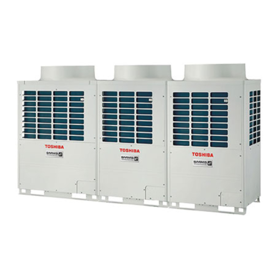
1. OUTLINE “Super Heat Recovery Multi System” is a multi air conditioning system which enables each indoor unit in a refrigerant line to independently select cooling or heating operation. As it is able to operate simultaneously in cooling and heating modes, further heat recovery becomes possible. - Page 10 1-1. Component Multi Using High-efficiency Refrigerant R410A 1. Outdoor units Inverter unit Corresponding HP Appearance 8 HP 10 HP 12 HP Model name Heat pump MMY- MAP0802FT8 MAP1002FT8 MAP1202FT8 Cooling capacity (kW) 22.4 28.0 33.5 Heating capacity (kW) 25.0 31.5 37.5...
- Page 11 4. Flow selector units (FS unit) Model name Usage Appearance RBM-Y1121FE Capacity rank for indoor unit : Type 007 to 030 RBM-Y1801FE Capacity rank for indoor unit : Type 036 to 056 RBM-Y2802FE Capacity rank for indoor unit : Type 018 to 096 * Accessory part (Sold separately): Connection cable kit (RBC-CBK15FE), up to 15m.
- Page 12 Cooling Heating Type Appearance Model name Capacity rank Capacity code capacity (kW) capacity (kW) 018 type MMD-AP0181H MMD-AP0241H 024 type Concealed Duct High Static MMD-AP0271H 027 type Pressure Type MMD-AP0361H 036 type 11.2 12.5 MMD-AP0481H 048 type 14.0 16.0 MMD-AP0071SPH 007 type 009 type MMD-AP0091SPH...
- Page 13 n Remote controllers Name Wired remote controller Simple wired remote controller Weekly timer CODE No. SuMoTuWeTh Fr Sa DATA SETTING TEST PROGRAM1 TEST ˚C UNIT No. SETTING ˚F ERROR PROGRAM2 R.C. PROGRAM3 TEMP. ON / OFF Appearance WEEKLY TIMER TIMER SET MODE TIME SWING/FIX...
-
Page 14: Wiring Diagram
1 2 3 4 5 1 2 3 4 5 1 2 3 4 5 6 4 3 1 2 5 1 2 3 4 5 1 2 3 4 5 1 2 3 4 5 6 4 3 1 2 5 5 4 3 2 1 CN334 CN333... - Page 15 6 4 3 1 2 5 6 4 3 1 2 5 1 2 3 4 5 6 (BLU) (GRN) (RED) (BLU) CN083(WHI) CN068 CN033 1 2 3 CN030 1 2 3 4 5 6 CN082 Color CN104 RY007 indication (YEL) RED : RED P301...
- Page 16 6 4 3 1 2 5 6 4 3 1 2 5 1 2 3 4 5 6 (BLU) (GRN) (RED) (BLU) CN083(WHI) 1 2 3 1 2 3 4 5 6 CN068 CN033 CN030 CN082 Color CN104 RY007 (YEL) indication CN301 (BLK)
- Page 17 RED BLK ORN BLU YEL CN083 3 CN033 3 CN030 1 2 3 4 5 6 CN068 CN082 (WHI) (BLU) (GRN) (RED) (BLU) 1 2 3 4 5 6 CN104 RY007 (YEL) P301 RY002 RY001 CN102 (RED) RY004 RY006 CN101 (BLK) (GRY) CN304...
- Page 18 Color Parts name Symbol indication Fan motor RED : RED Indoor temp sensor WHI : WHITE Temp sensor YEL : YELLOW Temp sensor BLU : BLUE Temp sensor BLK : BLACK Louver motor GRY: GRAY High ceiling setup Drain pump motor PNK : PINK 1 2 3 4 5 Float switsh...
- Page 19 1 2 3 6 4 3 1 2 5 1 2 3 6 4 3 1 2 5 CN333 1 2 3 4 5 6 CN82 CN33 CN34 CN68 (WHI) (BLU) (WHI) (RED) 1 2 3 4 5 6 1 2 3 4 5 3 2 1 (BLU) CN334...
- Page 20 (Option) Spark killer 43F1 Color indication CN100 (BLU) (GRN) RED : RED CN083(WHI) (BRN) 1 2 3 1 2 3 CN068 CN033 WHI : WHITE YEL : YELLOW CN104 CN102 CN101 (BLK) RY007 BLU : BLUE CN030 (YEL) (RED) (BLK) CN080 P301 BLK : BLACK...
- Page 21 1 2 3 4 5 1 2 3 4 5 CN334 CN333 1 2 3 4 5 CN82 1 2 3 4 5 CN33 CN34 CN68 (WHI) (WHI) (BLU) (WHI) (RED) 5 4 3 2 1 1 2 3 4 5 1 2 3 (BLU) RY302...
- Page 22 1 2 3 1 2 3 CN334 CN333 2 3 4 5 6 (WHI) (WHI) 1 2 3 4 5 6 1 2 3 4 5 CN82 CN33 CN34 CN104 CN102 CN101 CN100 (BLU) (WHI) (RED) (YEL) (RED) (BLK) (BRW) CN68 RY302 CN103...
- Page 23 Color identification Louver BROWN Pulse motor motor WHITE valve indicates the terminal block, letter at inside YELLOW indicates the terminal number. motor BLUE BLACK 2. A dotted line and broken line indicate the GRAY wiring at site. PINK ORANGE indicates the control P.C. board. GRN &...
- Page 24 RED BLK ORN BLU YEL 1 2 3 4 5 6 3 CN030 CN083 CN068 CN033 CN082 (WHI) (BLU) (GRN) (BLU) (RED) 1 2 3 4 5 6 CN104 RY007 (YEL) P301 (BLK) RY002 RY001 CN102 (RED) RY004 RY006 CN101 (GRY) (BLK) CN304...
- Page 25 RED BLK ORN BLU YEL RED BLK ORN BLU YEL CN083 CN083 CN068 CN033 1 2 3 4 5 6 (WHI) (WHI) (BLU) (GRN) 1 2 3 4 5 6 For AP0071BH,AP0091BH,AP0121BH CN030 CN082 CN104 (RED) (BLU) RY007 (YEL) R301 (BLK) RY002 RY001...
- Page 26 RED BLK ORN BLU YEL CN083 CN068 3 CN033 3 CN030 1 2 3 4 5 6 CN082 (WHI) (BLU) (GRN) (RED) (BLU) 1 2 3 4 5 6 CN104 RY007 (YEL) P301 (BLK) RY002 RY001 CN102 (RED) RY004 RY006 CN101 (BLK) (GRY)
- Page 27 Non Drain pump type ("SH" Type) Non Drain pump type Drain pump type ("SH" Type) ("SPH" Type) CN34 CN68 (BLU) (RED) (External static pressure setup) 1 2 3 Color indication CN334 CN333 CN82 CN33 CN34 1 2 3 4 5 6 RED : RED (RED) (WHI)
- Page 28 – Pressure Pressure Option Option Option Option Option PMV1 PMV2 PMV3 Sensor Sensor Board Board Board Board Board 63H1 63H2 U1 U2 U3 U4 U5 U6 – CN506(BLK) 6 5 4 3 2 1 6 5 4 3 2 1 6 5 4 3 2 1 4 3 2 4 3 2 1...
- Page 29 Flow Selector unit Indoor unit Supplied wire (Power supply) RBM-Y1802FE only Earth screw RBM-Y2802FE RBM-Y2802FE only only SVD SVD SVSS SVDD Control P.C. board for indoor unit CN01 CN10 CN67 (RED) (WHI) (BLK) Control P.C. board 1 2 3 4 CN81 MCC-1431 SVDD SVSS...
-
Page 30: Parts Rating
3. PARTS RATING 3-1. Indoor Unit 4-way Air Discharge Cassette Type Model MMU-AP 0091H 0121H 0151H 0181H 0241H 0271H 0301H Fan motor SWF-230-60-1 Drain pump motor ADP-1409 Float switch FS-0218-102 TA sensor Lead wire length : 155mm TC1 sensor Ø4 size lead wire length : 1200mm Vinyl tube (Blue) TC2 sensor Ø6 size lead wire length : 1200mm Vinyl tube (Black) TCJ sensor... - Page 31 1-way Air Discharge Cassette (Compact type) Type Model MMU-AP 0071YH 0091YH 0121YH Fan motor AF-200-22-4N-1 Running capacitor for fan motor AC 400V, 1µF Drain pump motor PJD-05230TF-1 Float switch FS-0208-602 Control P.C. board transformer TT-13 Pulse motor EDM-MD12TF-3 Pulse motor valve EDM-B25YGTF TA sensor Lead wire length : 818mm...
- Page 32 Concealed Duct High Static Pressure Type Model MMD-AP 0181H 0241H 0271H 0361H 0481H Fan motor STF-200-160-4B STF-200-160-4A STF-200-260-4C STF-200-260-4B Running capacitor for fan motor AC 500V, 4µF AC 400V, 8µF AC 450V, 6µF AC 400V, 8µF Drain pump motor ADP-1409 Float switch FS-0218-102-6 Pulse motor...
- Page 33 Floor Standing Cabinet Type Model MML-AP 0071H 0091H 0121H 0151H 0181H 0241H Fan motor AF-200-19-4F AF-200-45-4F AF200-70-4K Running capacitor for fan motor AC450V, 1.2µF AC400V, 1.8µF AC450V, 2µF Transformer TT13 Pulse motor EDM-MD12TF-3 Pulse motor valve EDM-B25YGTF EDM-B40YGTF TA sensor Lead wire length : 818mm Vinyl tube TC1 sensor Ø4 size lead wire length : 1200mm Vinyl tube (Blue)
- Page 34 3-2. Outdoor Unit Model MMY- MAP0802FT8 MAP1002FT8 MAP1202FT8 Compressor DA421A3FB-23M Output: : 3.75kW × 2 4-way valve coil (Heat pump only) LB64046 AC220-240V 50Hz Pulse motor valve coil VPV-MOAJ524C0 HAM-MD12TF-3 DC12V AC220–240V 50Hz 2-way valve coil SV2, SV3A, SV3B, SV3C, SV3D, SV3E SV41, SV42, SV5, SV6, SV11, SV12 VPV-122DQ1 SV2, SV3C, SV3D, SV3E, SV6, SV12...
- Page 35 TO sensor TE sensor TS2 sensor Check joint (Low pressure) Low pressure sensor SV2 valve SV42 valve SV3D valve SV3E valve SV3C valve SV11 valve SV41 valve SV5 valve SV6 valve SV3A valve TK1, TK2 sensor High pressure TS1 sensor SV12 valve TD1 sensor 4-way valve...
- Page 36 3-6. Name of Each Part [Concealed Duct Type] 3-6-1. Indoor Unit Sold Separately Parts Air outlet flange Earth screw Discharge duct connection. Earth screws are situated [4-way Air Discharge Cassette Type] inside the electric parts box. Air outlet/Air outlet louver 2-way discharge/3-way discharge Select air flow direction in cooling or 2-way discharge or 3-way discharge can be...
- Page 37 3-7. Parts Name of Remote Controller Air outlet/Air outlet louver Display section Changes the direction of the air flow. In the illustration, all of the indicators are displayed for the purpose of explanation. CODE No. In normal operation, only the icons relevant to the mode of operation would be DATA SETTING TEST...
- Page 38 Operation section 3-8. Correct Usage Push each button to select the desired operation. When the product is operated for the first time, or after the SET DATA value has been changed, the procedure This remote controller can operate up to a maximum 8 indoor units. below should be followed.
- Page 39 How to set up the air direction REQUIREMENT SWING/FIX Push button. [In Cooling operation] Every push of the button, the air direction changes. • The operation starts after approximately 1 minute. [In Heating operation] In Heating operation • In heating operation, the fan operation may continue for approximately 30 seconds after the air condi- Set the air outlet louver downward.
- Page 40 2-way discharge or 3-way discharge can be selected according to the configuration of the room. For details, Under Ceiling Type, 1-way Air Discharge Cassette Type (2SH Series) consult with the dealer from which you have purchased the air conditioner. • When the air conditioner is stopped, the horizontal louver (Up/Down air direction adjustment INFORMATION plate) automatically directs upward.
- Page 41 Right/Left air direction adjustment Floor Standing Cabinet Type To change the air outlet direction to the right or left side, set the vertical louver located behind the horizontal louver to the desired direction. [In Cooling operation] INFORMATION In cooling operation, set the air outlet louver with a horizontal set point so that the cold air diffuses the whole room.
- Page 42 3-10. Timer Operation Floor Standing Type Adjustment of air Flow direction upwards/downwards The type of timer operation can be selected from the following three types. OFF timer : The operation stops when the time on the timer has reached the set time. [In Cooling operation] Repeat OFF timer : The unit will stop, every time the set time period has elapsed.
- Page 43 3-11. Installation 3-12. Maintenance Installation location Cleaning of air filter • When [FILTER] is displayed on the remote controller, its is time to check and if necessary clean the filter. WARNING • Clogging of air filter decreases the cooling/heating effect. •...
- Page 44 Re-installing the air filter High Wall Type • Insert the upper portion of air filter confirming alignment with the right and left edges of the indoor unit until it (Model : 1H series) is located. • Push the projection at the center of the air filter. •...
- Page 45 If you do not plan to use the unit for more than 1 month 3-13. Air Conditioner Operations and Performance 1. Operate the fan for 3 to 4 hours to dry the inside of the unit Check before operation • Operate “FAN” mode. WARNING •...
- Page 46 Air conditioner operating conditions 3-15. When the Following Symptoms are Found For specified performance, operate the air conditioner under the following temperature conditions: Check the points described below before contacting your local service repair center. Cooling operation Outdoor temperature : –10°C to 43°C (Dry-bulb temp.) Symptom Cause Room temperature...
- Page 47 Confirmation and check When a error has occurred in the air conditioner, CODE No. the check code and the indoor unit No. will appear on the display part of the remote controller. UNIT No. The check code is only displayed during while the R.C.
-
Page 48: Refrigerant Piping Systematic Drawing
4. REFRIGERANT PIPING SYSTEMATIC DRAWING 4-1. Inverter Unit (8, 10, 12HP) Model: MMY-MAP0802FT8, MAP1002FT8, MAP1202FT8 Propeller fan Fan motor Sensor (TE1) (Right side) Sensor Strainer (TO) Main heat exchanger Pulse motor valve (Left side) Solenoid valve Main heat exchanger (SV12) (PMV1) (PMV2) Sub heat exchanger (Right side) - Page 49 4-2. Explanation of Functional Parts Functional part name Functional outline Solenoid valve SV3A (Connector CN324: Red) Closed : Allows oil to collect/remain in the oil tank. Open : Allows oil to exit the oil tank. SV3B (Connector CN313: Blue) Open : Allows oil to return to the outdoor unit via the balance pipe.
-
Page 50: Operation Mode
Functional part name Functional outline Pressure High pressure sensor (Connector CN501: Red) sensor 1) Detects high pressure and uses it to control the capacity of the compressor. 2) Detects high pressure during all cooling operation and uses it to control the fan when cooling with low outside air. - Page 51 Configuration of outdoor unit heat exchanger Flow Selector Unit (FS Unit) RBM-Y1122FE Liquid pipe Discharge gas pipe Suction gas pipe Propeller fan Strainer Strainer Capillary Capillary tube tube Capillary Fan motor Check tube valve SVDD SVSS Strainer To indoor To indoor liquid side gas side Main heat exchanger...
- Page 52 4-3. Indoor Unit Liquid side Gas side Strainer Capillary tube Air heat exchanger at indoor side Pulse Motor Valve (PMV) Distributor Sensor (TCJ) Sensor (TC2) Sensor (TC1) Sensor Fan motor (TA) (NOTE) MMU-AP0071YH to AP0121YH type air conditioners have no TC2 sensor. Functional part name Functional outline Pulse Motor Valve PMV...
-
Page 53: System Refrigerant Cycle Drawing
5. SYSTEM REFRIGERANT CYCLE DRAWING 5-1. Refrigerant Piping Systematic Diagram in System Selection of operation mode For the selection of each operation mode, refer to the below table: “Stop Once” this means the system does not operate for 3 minutes after operation before update has stopped. After update Mainly cooling, partly Mainly heating, partly... - Page 54 5-2. All cooling operation (Operation of cooling only) In high outside temperature (10°C or more: Criterion) Header unit Follower unit Sensor Sensor Main heat exchanger Main heat exchanger Main heat exchanger Main heat exchanger SV12 SV12 PMV1 PMV2 PMV1 PMV2 PMV3 PMV3 4-Way valve...
- Page 55 In low outside temperature (15°C or less: Criterion) Header unit Follower unit Sensor Sensor Main heat exchanger Main heat exchanger Main heat exchanger Main heat exchanger SV12 SV12 PMV1 PMV2 PMV1 PMV2 PMV3 PMV3 4-Way valve 4-Way valve SV11 SV11 Pd sensor Pd sensor Pd sensor...
- Page 56 5-3. All heating operation (Operation of heating only) Header unit Follower unit Sensor Sensor Main heat exchanger Main heat exchanger Main heat exchanger Main heat exchanger SV12 SV12 PMV1 PMV2 PMV1 PMV2 PMV3 PMV3 4-Way valve 4-Way valve SV11 SV11 sensor sensor Pd sensor...
- Page 57 5-4. Mainly Cooling, Partly Heating Operation (Cooling/heating simultaneous operation with subjective cooling operation) Header unit Follower unit Sensor Sensor Main heat exchanger Main heat exchanger Main heat exchanger Main heat exchanger SV12 SV12 PMV1 PMV2 PMV1 PMV2 Operating Operating for condenser for condenser PMV3 PMV3...
- Page 58 5-5. Mainly Heating, Partly Cooling Operation (Cooling/heating simultaneous operation with subjective heating operation) Header unit Follower unit Sensor Sensor Main heat exchanger Main heat exchanger Main heat exchanger Main heat exchanger SV12 SV12 PMV1 PMV2 PMV1 PMV2 PMV3 PMV3 4-Way valve 4-Way valve SV11 SV11...
- Page 59 5-6. Defrost Header unit Follower unit Sensor Sensor Main heat exchanger Main heat exchanger Main heat exchanger Main heat exchanger SV12 SV12 PMV1 PMV2 PMV1 PMV2 PMV3 PMV3 4-Way valve 4-Way valve SV11 SV11 sensor sensor Pd sensor Pd sensor SV3D SV3D Liquid...
-
Page 60: Control Outline
6. CONTROL OUTLINE 6-1. Indoor Unit 6-1-1. Control Specifications Item Outline of specifications Remarks Power supply (1) Identification of outdoor unit is reset. When the power supply is reset, the outdoor units are individually identified and communication is established. (2) Check code clear When the power supply is reset, the check code is also reset. - Page 61 Item Outline of specifications Remarks Prevention of (1) In all heating operation, the upper limit of the fan tap is set by cold air one with higher temperature of TC2 sensor and TCJ sensor. discharge • When B zone has continued for 6 minutes, the operation •...
- Page 62 Item Outline of specifications Remarks Recovery control (1) The indoor unit which stops operation, thermostat is OFF, • Recovery operation is for cooling or operates in FAN mode opens PMV of the indoor unit by usually executed every 2 refrigerant and oil the specified opening degree when cooling refrigerant or oil hours.
- Page 63 Item Outline of specifications Remarks “ ” and “ ” <Operation standby> ..Display on remote controller • “ ” goes on. display (1) • “P05” is one of displays of power wire missing. (Operation and • “P05” of power cable is detected. heating stand-by) •...
- Page 64 6-2. Outdoor Unit 6-2-1. Operation Start/Operation End The compressor, solenoid valve, pulse motor valve (PMV), outdoor fan, etc. are controlled by a command from the indoor controller. The follower outdoor unit starts/stops by a command from the header outdoor unit. Item Operation explanation and applied data, etc.
- Page 65 Item Operation explanation and applied data, etc. Remarks Capacity control 1) The capacity request command received from the • Min. frequency: 26Hz indoor controller determines the inverter frequency control of the outdoor unit. 2) The two compressors in each outdoor unit swap starting order on successive operation.
- Page 66 Item Operation explanation and applied data, etc. Remarks Oil short This control is provided to prevent oil shortage occurring in the protective compressors of each outdoor unit. control The control is achieved by ON/OFF operation of the solenoid valves SV3A, SV3B, SV3C and SV3D. (1) Oil-short protective control The oil shortage protection control function stops the outdoor •...
- Page 67 Item Operation explanation and applied data, etc. Remarks Release valve (1) SV2 gas balance control control In order to decrease the starting load on the compressor, SV2 valve is opened during the time the compressor is ‘OFF’, and the gas is balanced.
- Page 68 Item Operation explanation and applied data, etc. Remarks Compressor Each compressor is stopped should the Pd pressure sensor reach a stop due to value of 3.5 MPa. This control is performed by the header unit and high pressure any follower units. release Case heater Heating is provided for both the compressor case and accumulator.
- Page 69 Other cautions 1. Cooling operation in low ambient temperatures 1) The indoor unit freeze prevention control system (TC sensor) may decrease the command frequency to the outdoor unit when low coil temperatures are detected. 2) The cooling capacity control may decrease the command frequency to the outdoor unit when low ambient temperature is detected.
- Page 70 Oil equation control schematic diagram Header outdoor unit Follower outdoor unit (MMY-MAP1202FT8) (MMY-MAP1202FT8) Unit to Unit to send oil received oil Sensor Sensor Main heat exchanger Main heat exchanger Main heat exchanger Main heat exchanger SV12 SV12 PMV1 PMV2 PMV1 PMV2 PMV3 PMV3...
-
Page 71: Applied Control
7. APPLIED CONTROL 7-1. Indoor Unit 7-1-1. Setup of Selecting Function in Indoor Unit (Be sure to Execute Setup by a Wired Remote Controller) <Procedure> Execute the setup operation while the unit stops. TEMP. ON / OFF TIMER SET MODE TIME SWING/FIX VENT... - Page 72 Table: Function selecting item code (DN) (Items necessary to perform the applied control at the local site are described.) Item Description At shipment Filter display delay 0000 : None 0001 : 150H According to type timer 0002 : 2500H 0003 : 5000H 0004 : 10000H Dirty state of filter 0000 : Standard...
- Page 73 TYPE Item code [10] Setup data Type Abbreviated Model name 0000 1-way Air Discharge Cassette MMU-AP XXX SH 0001 4-way Air Discharge Cassette MMU-AP XXX H 0002 2-way Air Discharge Cassette MMU-AP XXX WH 0003 1-way Air Discharge Cassette (Compact type) MMU-AP XXX YH 0004 Concealed Duct Standard...
- Page 74 7-1-2. How to Set Up the Cooling Only Indoor Unit When connecting an indoor unit for use in cooling only. A flow selector unit is not connected. It is necessary to setup the unit. Perform setup as per the following procedure. Setup of the indoor unit is performed by use of a wired remote controller.
- Page 75 7-1-3. Setting When Connecting Multiple Indoor Units to a FS unit Cautions to connection of indoor unit • When connecting multiple indoor units to a single FS unit, it is necessary to set up the Item code. This should be done after the addressing of the units. •...
- Page 76 n In case of not setting 01 to Item code “0E” When more than one indoor unit has been set up as a group to one FS unit and you have forgotten to set 01 on Item code “0E” on all the indoor units, the following may occur: 1) When AUTO operation is selected on the remote controller and cooling operation and heating operation are required, hot air may be discharged from the cooling operation unit or cool air may be discharged from the heating operation unit (or fan stops).
- Page 77 7-1-4. Applied Control in Indoor Unit n Remote location ON/OFF control box (TCB-IFCB-4E) [Wiring and setup] • Use the exclusive connector for connection with the indoor control P .C. board. • In a group control, the system can operate when connecting with any indoor unit (Control P .C. board) in the group.
- Page 78 n Ventilating fan control from remote controller [Function] • The start/stop operation can be operated from the wired remote controller when air to air heat exchanger or ventilating fan is installed in the system. • The fan can be operated even if the indoor unit is not operating. •...
- Page 79 n Leaving-ON prevention control [Function] • This function controls the indoor units individually. It is connected with cable to the control P .C. board of the indoor unit. • In a group control, it is connected with cable to the indoor unit (Control P .C. board), and the item code set to the connected indoor unit.
-
Page 80: Specifications
7-2. Outdoor Unit 7-2-1. Applied Control in Outdoor Unit The following functions become available by setting the switches on the outdoor interface P .C. board. Function Switch No. Outdoor fan high static pressure shift SW10 Interface P.C. board of outdoor unit Switch position detail SW10 For setup of outdoor fan high static pressure shift... - Page 81 7-2-2. Applied Control in Outdoor Unit The following functions are available by using a separately supplied P .C. board. Set up the switches on the outdoor unit (U1). Function Switch No. Connector No. Used control P.C. board Power peak-cut control (Standard) SW07 CN513 TCB-PCDM2E...
- Page 82 7-2-2-1. Power Peak-cut Control (Standard) Operation Header outdoor unit interface P.C. board SW07 The upper limit capacity of the outdoor unit is restricted Set up Bit 1. based on the demand request signal from outside. : Display lamp during power peak-cut control (Setup CN513 (BLU) SW1 : Power peak-cut ON switch...
- Page 83 7-2-2-2. Power Peak-cut Control (Expansion) Header outdoor unit interface P.C. board Operation SW07 The upper limit capacity of the outdoor unit is restricted Set up Bit 1. based on the demand request signal from outside. ON Bit 2. : Display lamp during Power peak-cut control (Setup to CN513 (BLU) Header...
- Page 84 7-2-2-3. Snowfall Fan Control Operation Header outdoor unit interface P.C. board The outdoor unit fan operates when a Snowfall signal is received. Terminal Input signal Operation CN509 (4P BLK) Snowfall fan control Connection cable (Operates outdoor unit fan.) External master PJ17 COOL (4P WHI)
- Page 85 7-2-2-5. Night Operation Control Operation Header outdoor unit interface P.C. board Reduce emitted noise during night by resting the compressor and fan speed. Terminal Input signal Operation CN508 (4P RED) Night (sound reduction) Connection cable operation control COOL External master PJ17 (4P WHI) (SMC)
-
Page 86: Test Operation
8. TEST OPERATION 2. In case that a central control system is connected (Before address setup) 8-1. Procedure and Summary of Test Operation A test operation is executed in the following procedure. When a trouble or an error occurs in each step, remove causes of a trouble or an error referring to the section “9. - Page 87 3. Connection check between Flow Selector Unit (FS Unit) and indoor unit Check list 2 Calculate the additional amount of refrigerant from the following: Additional amount Actual liquid Additional amount of Corrective amount of × × Remote Remote Remote Indoor unit Indoor unit Indoor unit of refrigerant (B)
- Page 88 8-3. Check at Main Power-ON 8-4. Address Setup After turning on the main power of the indoor units and outdoor unit in the refrigerant line to be executed with a After power-ON, set up the indoor address from the interface P.C. board of the outdoor unit. test operation, check the following items in outdoor and each indoor unit.
- Page 89 8-4-3. Address Setup Procedure REQUIREMENT Group control over (Example) multiple refrigerant lines In this air conditioner, it is required to set up address to the indoor unit before starting opera- • When a group control is performed over the tion. Set up the address according to the following setup procedure. multiple refrigerant lines, be sure to turn on the Cabling systematic...
- Page 90 8. How to set up the terminal resistance Manual address setup from remote controller When all the address setups have finished in the same refriger- Header unit interface P.C. board In case to decide an address of the indoor unit prior to finish of indoor wiring work and unpracticed outdoor ant circuit system, put the terminal resistance in the same wiring work (Manual setup from remote controller) central control line into one.
- Page 91 Note 1) • To confirm all the unit numbers from an arbitrary wired remote controller; <Procedure> (Operation while the air conditioner stops) When setting the line address from the remote controller, do not use address 29 and 30. The address 29 and 30 cannot be set up in the outdoor unit. Therefore if they are incorrectly set up, a check The indoor unit No.
- Page 92 • To change all the indoor addresses from an arbitrary wired remote controller; Clearance of address (Return to status (Address undecided) at shipment from factory) (When the setup operation with automatic address has finished, this change is available.) Contents : Using an arbitrary wired remote controller, the indoor unit address can be changed for each same Method 1 refrigerant line An address is individually cleared from a wired remote controller.
- Page 93 8-4-4. Check after Address Setup When Central Control System is Connected In case of increase the address-undefined indoor units (Extension, etc.) When the central control system is connected, check the following setup has finished after address setup. If set up the indoor address of which address is undefined accompanied with extension of indoor units, replace- ment of P .C.
- Page 94 8-5. Troubleshooting in Test Operation If the phenomena appear, such as a check code is output or the remote controller is not accepted in power-ON after cabling work or in address setup operation, the following causes are considered. 8-5-1. A check Code is Displayed on the Remote Controller Check code Outdoor unit displayed on...
- Page 95 8-5-2. Operation from remote controller is not accepted and a check code is dis- played on 7-segment display of the interface P.C. board of the outdoor unit. 7-segment Remote display of Cause Countermeasures controller status outdoor unit No response Line addresses and indoor addresses of all the connected Set up addresses.
- Page 96 Incorrect wiring example (Fig. 1) Remote Header unit Incorrect example controller status 7-segment display No response E19-00 Header Header unit unit U3/U4 U5/U6 Indoorunit Indoorunit Indoorunit Indoorunit (Fig. 2) Remote Header unit Incorrect example controller status 7-segment display No response E19-02 U5/U6 Header...
- Page 97 8-6. Test Operation Check 8-6-1. Fan Operation Check START Push [START/STOP] button. When an error code has been displayed on the remote Select the operation mode [FAN]. controller, refer to Section 8-5-1. Is air discharged from the Check indoor fan, fan motor and fan circuit. discharge port of the indoor unit? (Ensure power has been isolated before removing any covers.) Check for items in contact with fan.
- Page 98 Wireless remote controller (Except 4-way Air Discharge Cassette type, Under Ceiling type and 1-way Air Discharge Cassette type (2 Series)) Remove the screw which fixes the name plate to the receiver part on the wireless remote controller. Remove the nameplate of the receiver section by inserting a minus screwdriver, into the notch at the bottom of the plate, and set the Dip switch to [TEST RUN ON].
- Page 99 In case of wireless remote controller (for Under Ceiling type and 1-way Air Discharge Cassette type (2 Series)) Procedure Description Turn on power of the air conditioner. The operation is not accepted for 5 minutes when power has been turned on at first time after installa- tion, and 1 minute when power has been turned on at the next time and after.
- Page 100 2. Test operation START Refer to “Test operation procedure” of Test operation for one indoor unit indoor remote controller. The operation does not start approx. 3 minutes Operation start after power-ON or after operation stopped. (NOTE) After power-ON, it may require Max. 10 minutes to start the operation due to the initial communication of the system.
- Page 101 (NOTE 1) Criteria for judging difference between suction and discharge temperature 1. Cooling After operation for a minimum of 30 minutes in [COOL] mode, check the dry bulb temperature difference. Temperature difference: 8°C or more between suction and discharge air of the indoor unit. (In Max-Hz operation) 2.
- Page 102 8-7. Service Support Function 8-7-1. Function to Start/Stop (ON/OFF) Indoor Unit from Outdoor Unit The following functions enables the start and stop of the indoor units using the switches on the interface P .C. board of the header unit. Function Outline Setup/Release 7-segment display...
- Page 103 1. All cooling test operation function This function is provided to change collectively the mode of all the indoor units connected to the same system for cooling test operation mode, using switches on the interface P .C. board of the header unit. Operation procedure Power ON Be sure to turn on power at the indoor side before power-ON of outdoor unit.
- Page 104 3. Batch start/stop (ON/OFF) function This function is provided to start/stop collectively all the indoor units connected to the same system by using switches on the interface P .C. board of the outdoor unit. Operation procedure Power ON Be sure to turn on power at the indoor side before power-ON of outdoor unit. If an error is already displayed under condition of SW01 [1], SW02 [1], SW03 [1], resolve the problem using the troubleshooting guide and then execute the...
- Page 105 4. Individual start/stop (ON/OFF) individual test operation function This function is provided to start/stop (ON/OFF) individually each indoor unit connected to the same system by using switches on the interface P .C. board of the header unit. Set SW01 [16] and set SW02, SW03 to indoor address No. (1 to 64) to be started (Refer to the following table ) - only the setup indoor unit starts operation.
- Page 106 8-7-2. Error Clearing Function 1. Clearing from the main remote controller [Error clearing in outdoor unit] Error of the outdoor unit is cleared by the unit of one refrigerant circuit system to which the indoor units oper- ated by the remote controller. (Error of the indoor unit is not cleared.) For clearing errors, the service monitor function of the remote controller is used.
- Page 107 2. Clearing from the interface P.C. board Using the switches on the interface P .C. board, this function is to clear the currently detected error for each refrigerant circuit system without resetting the power supply. Restart of error detection) Errors in both outdoor and indoor units are once cleared. (7-segment display) Set the rotary switches on the interface P.C.
- Page 108 8-7-3. Remote Controller Distinction Function This function is provided to distinguish the remote controller connected from the outdoor unit to the indoor unit for a refrigerant circuit system using switches on the interface P .C. board of the header unit. Distinction procedure Be sure turn on the power of the indoor unit prior Power ON...
- Page 109 8-7-4. Pulse Motor Valve (PMV) Forced Open/Close Function in Indoor Unit This function is provided to fully open or close forcibly the PMV for 2 minutes in all indoor units, using the switch operation on the interface P .C. board of the header unit. This function is also used to open the PMV fully when turning off the power and executing an operation, for example, vacuuming.
- Page 110 8-7-6. Solenoid Valve Forced Open/Close Function in Outdoor Unit This function is provided to forcibly open/close each solenoid valve mounted in the outdoor unit by use of the switches provided on the outdoor unit interface P .C. board. This function confirms the operation of each solenoid valve.
- Page 111 8-7-7. Fan Operation Check in Outdoor Unit This function is provided to check the fan operation on the interface P .C. board in the outdoor unit. The frequency of the fan speed can be controlled. Therefore utilize this function to check the operation or abnormal sound in the fan system. NOTE) Do not use this function during operation of the compressor.
- Page 112 8-7-8. Abnormal Outdoor Unit Discrimination Method <By Fan Operating Function> This function is provided to forcedly operate the fan of the outdoor unit in which an error occurred or the fan of the normal outdoor unit by the switch operation on the interface P .C. board in the header unit. To specify which one of the follower units connected to the system was faulty, use this function for the system stop due to a follower unit fault (Check code [E28]).
- Page 113 8-7-9. Manual Adjustment Function of Outside Temp (TO) Sensor This function is provided to fix TO sensor value manually by the switch operation on the interface P .C. board in the outdoor unit. When the unit stops abnormally due to TO sensor failure, etc, an emergent operation is avail- able by set up the value manually to position near the current outside temperature.
- Page 114 8-7-10. Indoor Fan Operation Check Function This function is provided to check operation of single indoor unit without using communication with the remote controller or outdoor unit. This function can be used regardless operating or stopping of the system. However, if this function is used for a long time, a trouble of the air conditioner may be caused. Therefore using of this function should be restricted to several minutes.
- Page 115 8-7-12. Monitor Function of Remote Controller Switch When using a remote controller with the model name RBC-ATM21E, the following monitor functions can be used. Calling of display screen [Contents] The temperature or the operation status of the remote controller, indoor unit, or each sensor of the outdoor unit can be known by calling up the service monitor mode from the remote controller.
-
Page 116: Troubleshooting
9. TROUBLESHOOTING 9-1. Troubleshooting Summary 1. Before troubleshooting 1) Applied models Super Heat Recovery Multi type models (Indoor unit: MMX-APXXX, Outdoor unit: MMY-MAPXXXFT8) 2) Required tools / measuring devices • Screwdrivers (Philips, Flat), spanner, longnose pliers, nipper, push pin for reset switch, etc. •... - Page 117 9-2. Check Method If an trouble occurs, the error code can be retrieved from the main remote controller/central remote controller (LCD display) or the header unit interface P .C. board (7-segment display). Using this self diagnostic function, the trouble can be identified using the table below. Check code list The following list shows all fault codes.
- Page 118 Check code Wireless remote controller Sensor block display Main Outdoor 7-segment display of receiving unit Check code name Detecting device remote AI-NET central controller control display Timer Ready Operation Flash display Auxiliary code ¤ ¤ — — ALT Indoor TCJ sensor error Indoor ¤...
- Page 119 Check code Wireless remote controller Sensor block display Main Outdoor 7-segment display of receiving unit Check code name Detecting device AI-NET central remote controller control display Timer Ready Operation display Flash Auxiliary code ¤ ¤ — — ALT Indoor fan motor error Indoor ¤...
- Page 120 New check code 1. Difference between the TCC LINK and AI-NET check code The displaying method of the check code changes in this model and onwards. AI-NET check code TCC Link Used characters Hexadecimal notation, 2 digits Alphabet + Decimal notation, 2 digits Characteristics of code Few classification of communication/ Many classification of communication/incorrect setup system...
- Page 121 9-3. Troubleshooting by Check Display on Remote Controller In case of wired remote controller (RBC-AMT31E) 1. Confirmation and check When a trouble occurs in the air conditioner, the CODE No. check code and the indoor unit No. are displayed UNIT No. on the of the remote controller.
- Page 122 In case of central remote controller (TCB-SC642TLE) ZONE ZONE GROUP CODE 1234 TEST UNIT No. SET DATA SETTING R.C. GROUP SELECT ZONE 1. Confirmation and check When a trouble occurred on the air conditioner, the check code and the indoor unit No. are displayed on the display section of the remote controller.
- Page 123 In case of AI-NET central remote controller 1. Operation for CHECK display When pushing the CHECK switch, the indoor unit No. (Network address No.) including the check data is displayed in the UNIT No. display section, and the check code is displayed in the set up temp. display section. CHECK switch Push for 0.5 seconds to display CHECK code.
- Page 124 9-4. Check Code and Check Position Displayed on the Remote Controller and Outdoor Unit (7-Segment Display of Interface) Check code Detected Outdoor 7-segment display Check code name Status Error detection condition Check item (position) Main AI-NET position remote central control controller Check code remote controller Sub-code...
- Page 125 Check code Detected Main AI-NET Outdoor 7-segment display Check code name Status Error detection condition Check item (position) position remote central control controller Check code Sub-code remote controller 01: Indoor/outdoor Automatic address start All stop • When indoor automatic address started, other •...
- Page 126 Check code Detected Check code Outdoor 7-segment display Status Error detection condition Check item (position) Main AI-NET position name remote central control controller Check code remote controller Sub-code 01: IPDU1 error IPDU All stop Communication of each IPDU • Check connection of communication connector and communication (P .C.
- Page 127 Check code Detected Outdoor 7-segment display Check code name Status Error detection condition Check item (position) Main AI-NET position remote central control controller Check code remote controller Sub-code 01: Compressor 1 side IPDU TH sensor error All stop • Resistance value of sensor is •...
- Page 128 Check code Detected Outdoor 7-segment display Check code name Status Error detection condition Check item (position) Main AI-NET position remote central control controller Check code remote controller Sub-code 01: Compressor 1 side IPDU Current detection All stop While header compressor •...
- Page 129 Check code Detected Outdoor 7-segment display Check code name Status Error detection condition Check item (position) Main AI-NET position remote central control controller Check code remote controller Sub-code — Protection for oil All stop The operating compressor Check all the outdoor units in the corresponding line. level drop detection detected oil shortage •...
- Page 130 Check code Detected Outdoor 7-segment display Check code name Status Error detection condition Check item (position) Main AI-NET position remote central control controller Check code remote controller Sub-code 01: TK1 oil circuit system error Oil level detective circuit system error All stop Temperature change of TK1 •...
- Page 131 Check code Detected Main Outdoor 7-segment display AI-NET Check code name Status Error detection condition Check item (position) position remote central control controller Check code Sub-code remote controller No. of indoor units with priority Duplicated indoor units with All stop Indoor units with priority were •...
- Page 132 Check code Detected Check code Outdoor 7-segment display Status Error detection condition Check item (position) Main AI-NET position name remote central control controller Check code remote controller Sub-code — — Indoor Indoor fan Corresponding • Check the lock of fan motor (AC fan). motor error unit only stops.
- Page 133 Check code Detected Check code Main AI-NET Outdoor 7-segment display Status Error detection condition Check item (position) position name remote central control controller Check code Sub-code remote controller 01: Compressor IPDU Heat sink All stop IGBT built-in temp sensor (TH) •...
- Page 134 Check code Detected Check code Error detection Outdoor 7-segment display Status Check item (position) Main AI-NET position name condition remote central control controller Check code remote controller Sub-code — Discharge All stop Discharge temperature • Check full opening of outdoor service valves (gas side, liquid side). temp TD2 error (TD2) exceeded 115°C.
- Page 135 Check code Detected Outdoor 7-segment display Check code name Status Error detection condition Check item (position) Main AI-NET position remote central control controller Check code remote controller Sub-code 0: IGBT shortage (Sub-code: 0) • Check fan motor. (Interphase short-circuit) FAN-IPDU Outdoor fan IPDU All stop error 1: Position detection...
- Page 136 Error detected by TCC-LINK central control device Check code Error detection Outdoor 7-segment display Detected position Check code name Status Check item (position) Display on AI-NET condition central control central control device remote controller Check code Sub-code — — TCC-LINK TCC-LINK central control Operation Signal is not transmit from...
- Page 137 Cautions when servicing for compressor 1. Removing wires of both compressors check output of the inverter as described below. How to check inverter output 1. Turn off the power supply. 2. Remove the compressor lead cables from the compressors. (Be sure to remove lead cables of both compressors.) 3.
- Page 138 9-5. Diagnosis Procedure for Each Check Code Check code Check code name Cause of operation [E03] / [97] Communication error between No communication from remote controller and Check code Check code name Cause of operation indoor and remote controller communication adaptor (TCC-L / AI-NET) (Detected at indoor side) [E01] / [–]...
- Page 139 Check code Check code name Cause of operation Check code Check code name Cause of operation [E06] / [04] Decreased number of indoor units [E07] / [–] Indoor/Outdoor 1. Communication lines (U1, U2) connection 1. Outdoor communication terminal resistance error between indoor and outdoor communication circuit error setup error (TCC-L / AI-NET)
- Page 140 Check code Check code name Cause of operation Check code Check code name Cause of operation [E08] / [96] Duplicated indoor addresses [E12] / [42] Automatic address start error Indoor addresses are duplicated. 1. When indoor automatic address started, other refrigerant circuit system was setting (TCC-L / AI-NET) (TCC-L / AI-NET) automatic address.
- Page 141 Check code Check code name Cause of operation Check code Check code name Cause of operation [E16] / [89] Connected indoor units 1. There are 48 or more connected indoor units. [E18] / [97/99] Communication error between Regular communication between indoor header capacity over indoor header and follower and follower is unavailable.
- Page 142 Check code Check code name Cause of operation Check code Check code name Cause of operation [E20] / [42] Unit connected to other line When starting automatic indoor address, a [E25] / [15] Duplicated address setup of termi- Addresses are duplicated by manual setting of during automatic address device in another refrigerant system is nal outdoor units...
- Page 143 Check code Check code name Cause of operation Check code Check code name Cause of operation [E31] / [CF] IPDU communication error [F01] / [0F] Indoor TCJ sensor error 1. Connection error of communication line TCJ sensor Open/Short between IPDU and I/F P.C. board (TCC-L / AI-NET) (TCC-L / AI-NET) 2.
- Page 144 Check code Check code name Cause of operation Check code Check code name Cause of operation [F04] / [19] TD1 sensor error TD1 sensor Open/Short [F10] / [0C] Indoor TA sensor error TA sensor Open/Short (TCC-L / AI-NET) (TCC-L / AI-NET) This check code means detection of Open/Short of TA sensor.
- Page 145 Check code Check code name Cause of operation Check code Check code name Cause of operation [F15] / [18] Outdoor temp sensor miscabling [F23] / [43] Ps sensor error 1. Misinstallation and misconnection of TE1 Output voltage error of Ps sensor (TE1, TL) sensor and TL sensor (TCC-L / AI-NET)
- Page 146 Check code Check code name Cause of operation Check code Check code name Cause of operation [F31] / [1C] Outdoor EEPROM error [H02] / [1d] Compressor error (Lock) 1. Outdoor unit power error (Voltage, noise, etc.) 1. Outdoor unit power line error (TCC-L / AI-NET) 2.
- Page 147 Check code Check code name Cause of operation Check code Check code name Cause of operation [H04] / [44] Compressor 1 case thermo operation 1. Case thermo circuit error [H06] / [20] Low-pressure protective operation 1. Service valve close (TCC-L / AI-NET) (TCC-L / AI-NET) 2.
- Page 148 Check code Check code name Cause of operation In some cases, it may be difficult to check for leakage or clogging of refrigerant in low ambient temperature condition. [H07] / [d7] Low oil level protection 1. Valves of balance pipes closed. In this case, it may take longer for the system to warm up before commencing checks.
- Page 149 Check code Check code name Cause of operation (*3) Check for solenoid valve of outdoor unit (for multiple outdoor unit system) [H08] / [d4] Oil level detective TK1 to TK4 sensor Open/Short a) Clogging check for SV3A valve temperature sensor error (TCC-L / AI-NET) •...
- Page 150 Check code Check code name Cause of operation Check code Check code name Cause of operation [H16] / [d7] TK2 detective circuit system error [H16] / [d7] TK3 temperature detective circuit error 1. Connection of TK2 sensor. 1. Connection of TK3 sensor. (Sub-code: 02) (Sub-code: 03) (TCC-L / AI-NET)
- Page 151 Check code Check code name Cause of operation Check code Check code name Cause of operation [H16] / [d7] TK4 temperature detective circuit error [L04] / [96] Duplicated setup of outdoor line address 1. Connection of TK4 sensor. Outdoor line addresses are duplicated. (Sub-code: 04) (TCC-L / AI-NET) 2.
- Page 152 Check code Check code name Cause of operation Check code Check code name Cause of operation [L07] / [99] Group line in individual indoor unit [L10] / [88] Outdoor capacity unset The group line is connected in the The model selection jumper of the outdoor I/F individual indoor unit.
- Page 153 Check code Check code name Cause of operation Check code Check code name Cause of operation [L18] / [8A] Flow selector unit system error [L29] / [CF] IPDU quantity error An indoor unit which has been operated in 1. Incorrect model setup in service for I/F P.C. cooling only mode is operated in heating mode board (TCC-L / AI-NET)
- Page 154 Check code Check code name Cause of operation Check code Check code name Cause of operation [L30] / [b6] Interlock in indoor unit [P03] / [1E] Discharge temp TD1 error Outside error was input. 1. Service valve of outdoor unit closed. from outside (TCC-L / AI-NET) (TCC-L / AI-NET)
- Page 155 Check code Check code name Cause of operation C All heating operation [P04] / [21] Actuation of 1. High-pressure SW error high-pressure SW (TCC-L / AI-NET) 2. Service valve closed Repair SV4 circuit. Is SV4 circuit normal? Coil error, clogging, 3.
- Page 156 Check code Check code name Cause of operation Check code Check code name Cause of operation [P07] / [1C] Heat sink overheat error [P12] / [11] Indoor fan motor error 1. Power voltage error 1. Cabling error of fan motor connector (TCC-L / AI-NET) 2.
- Page 157 Check code Check code name Cause of operation Check code Check code name Cause of operation [P13] / [47] Outdoor liquid back detection error [P15] / [AE] Gas leak detection 1. PMV1/PMV2 error 1. Outdoor unit service valve closed (TCC-L / AI-NET) 2.
- Page 158 Check code Check code name Cause of operation Check code Check code name Cause of operation [P15] / [AE] Gas leak detection [P17] / [bb] Discharge temp TD2 error 1. Outdoor unit service valve closed 1. Outdoor unit service valve closed (TCC-L / AI-NET) TD condition (Sub-code: 02) 2.
- Page 159 Check code Check code name Cause of operation Check code Check code name Cause of operation [P19] / [08] 4-way valve operation error [P20] / [22] High-pressure protective operation 1. 4-way valve error 1. Pd sensor error (TCC-L / AI-NET) 2.
- Page 160 Check code Check code name Cause of operation [P22] / [1A] Outdoor fan IPDU error 1. Fan lock (TCC-L / AI-NET) 2. Fan IPDU P.C. board error 3. Overload All heating operation 4. External cause such as power surge 5. Fan IPDU power P.C. board error Is connector connection of indoor Does heating indoor fan...
- Page 161 Check code Check code name Cause of operation Check code Check code name Cause of operation [P26] / [14] G-Tr short-circuit protection error [P29] / [16] Compressor position 1. Outdoor unit power error 1. Wire connection error. detective circuit error (TCC-L / AI-NET) 2.
- Page 162 Check code Check code name Cause of operation [–] / [97] AI-NET communication line error AI-NET communication line error (TCC-L / AI-NET) Are AI-NET X and Y Correct communication line. communication lines normal? Are connections of CN01, CN02, and CN03 connectors on network adaptor P.C.
- Page 163 9-6. 7-Segment Display Function n 7-segment display on the outdoor unit (Interface P.C. board) On the interface control P .C. board, a 7-segment LED is provided to check the operating status. The displayed contents are changed by combining the setup numbers of the rotary switches (SW01, SW02 and SW03) on the I/F P .C.
- Page 164 1. Data display of system information (Displayed on the header outdoor unit only) SW01 SW02 SW03 Display contents Refrigerant name Displays refrigerant name. Model with refrigerant R410A Model with refrigerant R407C System capacity [ 5] to [48] : 5 to 48HP [HP] No. of outdoor units...
- Page 165 2. Data display of outdoor unit information (Displayed on each outdoor unit) SW01 SW02 SW03 Display contents Error data Displays outdoor unit number: [U1] to [U4] Displays check code (Latest code only is displayed.) There is no check code: [– – –] There is sub-code: Check code [ ] for 3 seconds, sub-code [–...
- Page 166 3. Data display of outdoor cycle (Displayed on each outdoor unit) SW01 SW02 SW03 Display contents Pd pressure data Pd pressure (MPaG) is displayed with decimal data. (MPaG: Approx. 1/10 value of kg/cm G data) P d. Ps pressure data Ps pressure (MPaG) is displayed with decimal data.
- Page 167 5. Outdoor EEPROM check code display (Displayed on the header unit only) The latest check code written in EEPROM on each outdoor unit is displayed. (It is used when confirming the check code after power supply has been reset.) Set SW01 to 03 as shown in the following table and the push SW04 for 5 seconds or more to display an check code. 7-segment display SW02 SW03...
- Page 168 n Pressure sensor characteristics • I/O cable connection table High pressure side (Pd) Low pressure side (Ps) Pin No. Input/Output name Lead wire color Input/Output name Lead wire color OUTPUT White — — — — OUTPUT White Black Black • Output voltage — Pressure High pressure side (Pd) Low pressure side (Ps) 0.5 to 3.9 V DC...
- Page 169 9-8. Pressure Sensor Output Check 9-8-1. Outdoor Unit n Pd sensor characteristics 0 to 4.41MPa (0.5 to 5V output with 0 to 4.41MPa) ‚ ƒ ƒ Voltage check between CN501 pins on the outdoor unit I/F P .C. board (Tester rod at pin side) VOLT...
- Page 170 n Ps sensor characteristics 0 to 1.48MPa (0.5 to 5V output with 0 to 1.48MPa) ‚ ƒ ƒ Voltage check between CN500 pins on the outdoor unit I/F P .C. board (Tester rod at pin side) VOLT VOLT VOLT VOLT VOLT (MPa) (kg/cm²)
- Page 171 9-8-2. Flow Selector Unit (FS Unit) Leakage of SVD valve or SVS valve, etc; Positions to be checked and check code when a trouble such as miswiring occurred. Phenomenon which appears as result (Corresponding indoor unit or flow selector unit) Correspon Example of Trouble...
- Page 172 Phenomenon which appears as result (Corresponding indoor unit or flow selector unit) Correspon Example of Abnormal Part name Trouble mode Operation mode ding indoor Judgment and position to be checked refrigerant May become cooling sound Detection of unit flow almost normal ¡...
- Page 173 Suction gas pipe Suction gas pipe Suction gas pipe Discharge gas pipe Discharge gas pipe Discharge gas pipe Liquid pipe Liquid pipe Liquid pipe • SV11 ON • SVD ON • SVS ON • SVD leakage • SV11 ON • SVS ON...
-
Page 174: Configuration Of Control Circuit
Wired remote controller (Up to 2 units) Weekly timer Display Display driver Function setup Display Function setup Key switch Key switch DC5V Remote DC5V controller Power Power Secondary communication circuit circuit battery circuit Indoor unit Network adaptor (Option) Max. 8 units are connectable. *1 Network Indoor control P.C. - Page 175 Wired remote controller (Up to 2 units) Weekly timer Display Display driver Function setup Display Function setup Key switch Key switch DC5V Remote DC5V controller Power Power Secondary communication circuit circuit battery circuit Indoor unit Network adaptor (Option) Max. 8 units are connectable. *1 Network Indoor control P.C.
- Page 176 Indoor unit Network adaptor (Option) Wireless remote controller kit Network Sensor P.C. board Indoor control P.C. board (MCC-1402) Remote adaptor Remote Remote EEPROM controller P.C. board controller controller communication (MCC-1401) communication communication Emergent circuit Power circuit circuit operation DC20V circuit Central control DC12V AI-NET...
- Page 177 Indoor unit Network adaptor (Option) Network Indoor control P.C. board (MCC-1403) Remote adaptor Remote controller EEPROM P.C. board controller communication Wireless remote (MCC-1401) communication circuit DC20V controller kit circuit DC12V Central control AI-NET Remote remote controller DC5V communication TA sensor controller H8/3687 (Option)
- Page 178 Wired remote controller Weekly timer Display Display driver Function setup Display Function setup Key switch Key switch DC5V Remote DC5V controller Power Power Secondary communication circuit circuit battery circuit Indoor unit Network adaptor (Option) Wireless remote controller kit Network Sensor P.C. board Indoor control P.C.
- Page 179 Wired remote controller Weekly timer Display Display driver Function setup Display Function setup Key switch Key switch DC5V Remote DC5V controller Power Power Secondary communication circuit circuit battery circuit Indoor unit Network adaptor (Option) Network Indoor control P.C. board (MCC-1403) Remote adaptor Remote...
- Page 180 Filter/Option error input Microcomputer operation LED EEPROM DC fan output Power supply Optional power supply PMV output Remote controller power supply LED DC fan return Drain pump output Float SW Fan output TCJ sensor EXCT Remote controller inter-unit cable HA (T10) TC1 sensor TA sensor Used for...
- Page 181 Power transformer (Secondary side) (AC11V, 14V, 20V) Indoor/Outdoor communication (Spare) Power supply PMV output Indoor/Outdoor communication Microcomputer (Also used for communication of operation LED EEPROM the central control system) Power transformer (Primary side) (AC200V) Flap Remote controller power supply LED HA (T10) Optional output Remote controller...
- Page 182 MCC-1520 2-way Air Discharge Cassette Type, 1-way Air Discharge Cassette Type (1 Series), Concealed Duct High Static Pressure Type, Floor Standing Cabinet Type, Floor Standing Concealed Type, Floor Standing Type CN02 I G O +15V MCC-1520-01 COMPONENT SIDE Power supply trans side (Input) Control P.C.
- Page 183 10-1-4. Optional Connector Specifications of Indoor P.C. Board Connector Function Specifications Remarks Humidifier output CN66 DC12V In heating, thermo ON, Fan ON, Humidifier output ON * Humidifier provided, Drain pump ON is set up by CN70 ‚ Output short-circuit or from remote controller. (DN=40) ...
- Page 184 10-2. Outdoor unit Positions to be checked on the interface P.C. board (MCC-1429) CN03 backup For outdoor unit cable CN01 between outdoor units For inter-unit cable between CN03 indoor and outdoor units Pressure sensor (Ps) Pressure sensor (Pd) CN01 backup Option input/output UART CN508,509,510,...
- Page 185 Inverter P.C. board (MCC-1502) [IPDU1, IPDU2] Compressor output Power supply input +12V (AC400V) Input current sensor (T02) Communication between I/F and Comp. IPDU Reactor 2 (IPDU2 only is AC230V connected.) input DC330V output (IPDU1 only is connected.) Connection between IPDU1 and 2 Electrolytic condenser (+, -) DC330V input...
- Page 186 Power supply P.C. board for fan (MCC-1439) Communication between +12V I/F and fan IPDU Judgement AC230V input +12V terminal 1 – 5 +7V terminal 2 – 5 Communication between fan IPDU +7V output DC330V output (For Comp. IPDU) Electrolytic condenser CN500 DC330V output for fan IPDU (Judgemant : DC 180–370V)
- Page 187 10-2-1. Outdoor Interface P.C. Board Dip switch function exchange setup list Initial setup Part type Exchange contents at shipment SW01 Rotary SW 4bit 16 step Display / Operation switch (1) For 7-segment display / service operation SW02 Rotary SW 4bit 16 step Display / Operation switch (2) For 7-segment display / service operation SW03 Rotary SW 4bit 16 step Display / Operation switch (3) For 7-segment display / service operation...
-
Page 188: Backup Operations (Emergency Operation)
11. BACKUP OPERATIONS (EMERGENCY OPERATION) When a trouble occurs in an outdoor unit or in one of the compressors in an outdoor unit, the malfunctioning unit or compressor stops and a backup operation (emergency operation) is available through the other function- ing outdoor units and compressors. - Page 189 11-3. Backup Setup for Outdoor Unit Outline In this model, setup of the backup operation is available in either the header unit or the follower unit in a situa- tion where the outdoor units are defective. In a system in which two or more outdoor units are connected, carry out the backup operation on the outdoor unit if the error modes described below occur.
-
Page 190: Oil Level Judgment Display
12. OIL LEVEL JUDGMENT DISPLAY The judgment result of the current oil level of the compressor can be confirmed by the switch setup on the interface P .C. board on the outdoor unit. Confirm the result using the following procedure. 1. -
Page 191: Refrigerant Recovery When Replacing The Compressor
13. REFRIGERANT RECOVERY WHEN REPLACING THE COMPRESSOR 13-1. Refrigerant Recovery in the Malfunctioning Outdoor Unit A pump-down function is available in this system. For multiple outdoor unit systems, execute pump-down by using the normal outdoor units and the refrigerant can be recovered from the outdoor unit, which is to be repaired. 13-1-1. - Page 192 6. Fully close the service valve in the gas pipe of the malfunctioning outdoor unit approximately 10 minutes after the system has started. 7. Push SW04 of the malfunctioning outdoor unit, to display the pressure data (MPa). For each successive push of SW04, the data display changes as shown in the example below. Display Example [rd] [ 11] [Pd] [1.20]...
- Page 193 (Refrigerant recovery procedure (backup)) If the power of the malfunctioning unit cannot be turned on, the PMV cannot be opened, therefore the amount of recovered refrigerant decreases compared with the usual pump down operation. Using a refrigerant recovery device, recover the remaining gas in the unit and measure the recovered refrigerant, as the same amount of refrigerant will be required to be recharged after the repair.
- Page 194 [Setup for header unit] 9. The low pressure (Ps) data is displayed on the 7-segment display. Slowly close the service valve of the gas pipe and adjust so that a pressure of 0.12 MPa is displayed. 10. When the manifold gauge pressure of the malfunctioning outdoor unit is almost the same as that of the header unit in which the pressure adjustment has been made, fully close the service valve of the gas pipe in the header unit.
- Page 195 13-2. How to Operate the System During Repair of the Malfunctioning Outdoor Unit Procedure 1. Follow the aforementioned “13-1. Refrigerant Recovery in the Malfunctioning Outdoor Unit”. 2. Recover the refrigerant in the system by using a recovery device. The refrigerant amount to be recovered is determined based upon the capacity of the malfunctioning outdoor unit (see the following table).
- Page 196 13-3. Process after Repair After completion of the repair work, perform vacuuming of the outdoor unit using the following procedure. Procedure 1. Short CN30 on the interface P .C. board on the outdoor unit for which the repair work has been completed, to open the PMV fully.
-
Page 197: Leakage/Clogging Of Oil-Equalization Circuit
14. LEAKAGE/CLOGGING OF OIL-EQUALIZATION CIRCUIT Check code list for leakage, clogging of outdoor refrigerant circuit and oil circuit parts Trouble by clogging Position with trouble Unit issuing Phenomena Part name Check code to be detected (See next page.) check code (Corresponding unit) Outdoor PMV Corresponding unit... - Page 198 Propeller fan Fan motor Sensor (TE1) (Right side) Sensor Strainer (TO) Main heat exchanger Pulse motor valve (Left side) Solenoid valve Main heat exchanger (SV12) (PMV1) (PMV2) Auxiliary heat exchanger (Right side) Strainer Auxiliary heat exchanger (Left side) Check (PMV3) 4-Way valve valve Strainer...
-
Page 199: Replacing Compressor
15. REPLACING COMPRESSOR 15-1. Compressor Replacing Procedure (Outline) WARNING Never recover the refrigerant into outdoor unit. Be sure to use a refrigerant recovery device for refrigerant recovery for reinstallation or repair work. Recovery into the outdoor unit is unavailable; otherwise a serious accident such as rupture or ingury could occur. - Page 200 15-2. Replacing Compressor Exchanging a compressor When changing the compressor, extract oil from the defective compressor and based on the quality of the oil, make the decision of whether to change one or both compressors. If oil colour ASTM is 4.0 or more, both compressors should be replaced. CAUTION The compressor can weigh in excess of 20kg.
- Page 201 Color check of oil in the defective compressor • Lay the defective compressor down, extract a little oil from the oil-equalization pipe and then check the oil colour based on the oil colour sample. • Determine the number of compressors to replace based on the oil colour: •...
- Page 202 When replacing both the defective and normal compressors Removal of normal compressor • Remove the normal compressor in the same way as the defective compressor. Note) • Be sure to apply insulation to the removed cable terminals with insulating tape, etc. WARNING Be aware that if oil is present when brazing, a fire eruption could occur.
- Page 203 Installation of compressor • Install the compressor in the reverse procedure of removal. • When removing the compressor, the terminals may become loose. If this happens crimp them with pliers and then check there are no looseness. Note) • Only two hexagonal bolts are provided to fix the compressor. •...
- Page 204 15-3. Procedure to Identify the Cause of Compressor Oil Shortage Correct miscabling or incorrect Is there any disconnection, mis-cabling, installation of the sensors: or incorrect installation of sensors on the unit TK1: CN514/TK2: CN515 of which the compressor has been replaced? TK3: CN516/TK4: CN523 ®...
- Page 205 Propeller fan Fan motor Sensor (TE1) (Right side) Sensor Strainer (TO) Main heat exchanger Pulse motor valve (Left side) Solenoid valve Main heat exchanger (SV12) (PMV1) (PMV2) Auxiliary heat exchanger (Right side) Strainer Auxiliary heat exchanger (Left side) Check (PMV3) 4-Way valve valve Strainer...
-
Page 206: Replacing Procedure Of Parts
16. REPLACING PROCEDURE OF PARTS Part to be Work procedure Remarks exchanged Cabinet Discharge cabinet REQUIREMENT Wear protective clothing on your hands as other components may cause and injury etc. Disassembling 1) Stop the unit operation and turn off the power supply to the unit. - Page 207 Part to be Work procedure Remarks exchanged Propeller fan 3) Remove the flange nut fixing on the fan 3) Flange nut motor motor and propeller fan. (To tighten the nut, turn it clockwise.) 4) Remove the square washer. 5) Remove the propeller fan. NOTE Gently pull the straight upwards.
- Page 208 Part to be Work procedure Remarks exchanged Heat REQUIREMENT 2) Motor base exchanger Wear protective clothing on your hands as other components may cause and injury etc. Heat e Heat exchanger Heat exchanger xchanger Before beginning the procedure, ensure the (Left) (Left) (Left)
- Page 209 Part to be Work procedure Remarks exchanged HeInverter REQUIREMENT assembly M Removal of box Wear protective clothing on your hands as other components may cause and injury etc. 3 Scre 3) Screw Screw 1) Stop the unit operation and turn off the power supply to the unit.
- Page 210 Part to be Work procedure Remarks exchanged Inverter assembly REQUIREMENT M Removal of P .C. Wear protective clothing on your hands board and 4. IPDU P.C. board for fan as other components may cause and electric parts 1. Noise filter 2.
- Page 211 Part to be Work procedure Remarks exchanged Inverter assembly REQUIREMENT M Removal of P .C. Wear protective clothing on your hands board and as other components may cause and electric parts injury etc. 5. Reactor 1) Stop operation, and then turn the power 6.
- Page 212 Part to be Work procedure Remarks exchanged Pressure sensor posi- tions of 2-way valve coil SV3B SV3A SV3C Rear side Oil tank Liquid tank SV3D Accumulator Oil separator PS sensor SV11 Compressor(1) Compressor(2) SV41 SV42 PD sensor Front side SV12 Front side of air conditioner Temperature sensor posi-...
- Page 213 Part to be Work procedure Remarks exchanged Rear side of air conditioner Temperature sensor positions Accumulator and identification Rear side TK3 sensor(White) TK1 sensor(Black) Accumulator side (Front side) Oil separator TK2 sensor(Blue) Rear side TK4 sensor(Green) Liquid tank Oil tank Attachment/ This air conditioner has been designed so that vibration has detachment of...
- Page 214 Part to be Work procedure Remarks exchanged Attachment/ REQUIREMENT detachment of pipe fixing Wear protective clothing on your hands as rubber other components may cause and injury etc. Disassembling Compress the rubber to release the cup. 1) Squeeze the band either side of the clip to release.
- Page 215 Part to be Work procedure Remarks exchanged Exchange of REQUIREMENT accumulator Wear protective clothing on your hands as other components may cause and injury etc. Before beginning the procedure, ensure the refrigerant has been reclaimed from the outdoor unit, using a suitable refrigerant recovery device.
- Page 216 Part to be Work procedure Remarks exchanged Exchange of REQUIREMENT 4-way valve Wear protective clothing on your hands as other components may cause and injury etc. Before beginning the procedure, ensure the refrigerant has been reclaimed from the outdoor unit, using a suitable refrigerant recovery device.
-
Page 217: Board
17. P.C. BOARD 17-1. Indoor Unit 17-1-1. Exchange of P.C. Board for Indoor Service Part code Model type P.C. board model Label display on P.C. board MMU-AP 1WH series MMU-AP 1YH series MMU-AP 1SH series 431-6V-207 MMD-AP 1H series MCC-1403 03RD M01 MML-AP 1H series... - Page 218 Method 2 Before exchange, it is impossible to read out the setup contents due to EEPROM error. Exchange of P .C. board for service & power ON: Procedure 2 ò Writing-in of the setup data such as the model name, capacity code, indoor unit address high ceiling setup, connection setup of option, etc to EEPROM based upon customer’s information: Procedure 3 ò...
- Page 219 Procedure 2 : Exchange of P.C. board for service 1. Exchange P .C. board with a P .C. board for service. In this time, the jumper line (cut) setup or the (short-circuit) connecting connector setup on the previous P .C. board should be reflected on P .C.
- Page 220 Procedure 3 : Writing-in of setup contents to EEPROM (The EEPROM contents which are installed on the service P .C. board have been set up at shipment from the factory.) TEST 1. Push buttons simultaneously for 4 seconds or more. (Corresponds to number of the operation diagram of the remote controller in page 218.) is displayed in the UNIT No box.) In this time,...
- Page 221 Record the contents of the following before exchanging P.C. boards. (Item code list) Item Memo Setup at shipment from factory Filter sign lighting time According to type Dirty condition of filter 0000: Standard Central control address 0099: Undefined Heating inlet temp. shift 0002: +2°C (Floor standing: 0) * Automatic selection Cooling Auto mode existence...
- Page 222 17-2. Outdoor Unit 17-2-1. Cautions in Service for Compressor 1. When checking the inverter output, remove the both wires of the compressor as follows. 17-2-2. How to Check Inverter Output 1. Turn off the power supply. 2. Remove the compressor lead from the compressor. (Be sure to remove lead wires of both compressors.) 3.
- Page 223 17-2-4. How to Check Fan Power Supply P.C. Board and Fan IPDU The fan power supply P .C. board supplies DC power. It supplies DC280V for the fan IPDU, and DC12V and DC7V for the control power supply respectively. If the control power is not supplied, a communication error (Error code [E31]) is out.
- Page 224 17-2-5. Interface Board Replacement Procedure This service board is commonly installed in different models. If the board assembly is to be replaced, check the displayed inspection contents and replace the board with the correct version for the model and follow this procedure.
- Page 225 17-2-6. Comp-IPDU Board Replacement Procedure Manual This service board is commonly installed in different models. If the board assembly is to be replaced, replace it properly in with the correct version for the model and follow this procedure. Replacement steps 1.
- Page 226 17-2-7. Notice for Wiring Wiring for service shall be done according to the wiring diagram. Special caution is needed for the reactor, which has different connecting points on the COMP-IPDU1 and COMP-IPDU2. COMP-IPDU No.1 COMP-IPDU No.2 TO REACTOR 1 TO REACTOR 2 CN20 (REACTOR 1) CN08 (REACTOR 2) CN21 (REACTOR 1)
- Page 227 Inverter Assembly Configuration Fan IPDU BUS terminal block Power supply P.C. board for fan Relay connector Magnet swith IPDU1 IPDU2 Noise filter Interface P.C. board Power supply terminal block Over-current relay...
- Page 228 Copyright © 2005 TOSHIBA CARRIER CORPORATION, ALL Rights Reserved.