Toshiba Super MMU-AP0091H Service Manual
Super modular multi
Hide thumbs
Also See for Super MMU-AP0091H:
- Owner's manual (220 pages) ,
- Installation manual (181 pages) ,
- Owner's manual installation and operation (91 pages)
Table of Contents
Advertisement
SERVICE MANUAL
<4-way Air Discharge Cassette Type>
MMU-AP0091H, AP0121H, AP0151H,
MMU-AP0181H, AP0241H, AP0271H,
MMU-AP0301H, AP0361H, AP0481H
MMU-AP0561H
<2-way Air Discharge Cassette Type>
MMU-AP0071WH, AP0091WH, AP0121WH,
MMU-AP0151WH, AP0181WH, AP0241WH,
MMU-AP0271WH, AP0301WH
MMU-AP0481WH
(CHINA market only)
<1-way Air Discharge Cassette Type>
MMU-AP0071YH, AP0091YH, AP0121YH,
MMU-AP0151SH, AP0181SH, AP0241SH
<Concealed Duct Standard Type>
MMD-AP0071BH, AP0091BH, AP0121BH,
MMD-AP0151BH, AP0181BH, AP0241BH,
MMD-AP0271BH, AP0301BH, AP0361BH,
MMD-AP0481BH, AP0561BH
<Concealed Duct High Static Pressure Type>
MMD-AP0181H, AP0241H, AP0271H,
MMD-AP0361H, AP0481H, AP0721H,
MMD-AP0961H
<Under Ceiling Type>
MMC-AP0151H, AP0181H, AP0241H,
MMC-AP0271H, AP0361H, AP0481H
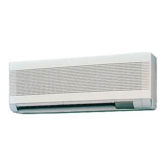
<High Wall Type>
MMK-AP0071H, AP0091H, AP0121H,
MMK-AP0151H, AP0181H, AP0241H
<Floor Standing Cabinet Type>
MML-AP0071H, AP0091H, AP0121H,
MML-AP0151H, AP0181H, AP0241H
<Floor Standing Concealed Type>
MML-AP0071BH, AP0091BH, AP0121BH,
MML-AP0151BH, AP0181BH, AP0241BH
<Floor Standing Type>
MMF-AP0151H, AP0181H, AP0241H
MMF-AP0271H, AP0361H, AP0481H
MMF-AP0561H
FILE NO. A03-009
<Inverter Unit>
MMY-MAP0501T8, MAP0601T8
MMY-MAP0801T8, MAP1001T8
MMY-MAP1201T8
<Inverter Unit>
MMY-MAP0501HT8, MAP0601HT8
MMY-MAP0801HT8, MAP1001HT8
MMY-MAP1201HT8
Heat Pump Model
<Inverter Unit>
MMY-MAP0501HT7, MAP0601HT7
MMY-MAP0801HT7, MAP1001HT7
MMY-MAP1201HT7
PRINTED IN JAPAN, May.,2004 ToMo
TENTATIVE
Advertisement
Table of Contents
Troubleshooting

Related Manuals for Toshiba Super MMU-AP0091H


Summary of Contents for Toshiba Super MMU-AP0091H
-
Page 1: Service Manual
FILE NO. A03-009 TENTATIVE SERVICE MANUAL Indoor Unit Outdoor Unit <4-way Air Discharge Cassette Type> Cooling Only Model MMU-AP0091H, AP0121H, AP0151H, MMU-AP0181H, AP0241H, AP0271H, <Inverter Unit> MMU-AP0301H, AP0361H, AP0481H MMY-MAP0501T8, MAP0601T8 MMU-AP0561H MMY-MAP0801T8, MAP1001T8 <2-way Air Discharge Cassette Type> MMY-MAP1201T8 MMU-AP0071WH, AP0091WH, AP0121WH, MMU-AP0151WH, AP0181WH, AP0241WH, MMU-AP0271WH, AP0301WH... - Page 2 WARNINGS ON REFRIGERANT LEAKAGE Important Check of Concentration Limit The room in which the air conditioner is to be NOTE : 2 installed requires a design that in the event of The standards for minimum room volume are as refrigerant gas leaking out, its concentration will follows.
-
Page 3: Safety Caution
NOTE A direct current motor is adopted for indoor fan motor in the Concealed Duct Standard Type air conditioner. Caused from its characteristics, a current limit works on the direct current motor. When replacing the high- performance filter or when opening the service board, be sure to stop the fan. If an above action is executed during the fan operation, the protective control works to stop the unit operation, and the check code “P12”... -
Page 4: Safety Caution
SAFETY CAUTION The important contents concerned to the safety are described on the product itself and on this Service Manual. Please read this Service Manual after understanding the described items thoroughly in the following contents (Indications/Illustrated marks), and keep them. [Explanation of indications] Indication Explanation... - Page 5 WARNING Before troubleshooting or repair work, check the earth wire is connected to the earth terminals of the main unit, otherwise an electric shock is caused when a leak occurs. If the earth wire is not correctly connected, contact an electric engineer for rework. Check earth wires.
- Page 6 WARNING After the work has finished, be sure to use an insulation tester set (500V mugger) to check the resistance is 2MΩ Ω Ω Ω Ω or more between the charge section and the non-charge metal section (Earth position). If the resistance value is low, a disaster such as a leak or electric shock is caused at user’s Insulator check side.
-
Page 7: Safety Caution Concerned To New Refrigerant
• New Refrigerant (R410A) This air conditioner adopts a new HFC type refrigerant (R410A) which does not deplete the ozone layer. 1. Safety Caution Concerned to New Refrigerant The pressure of R410A is high 1.6 times of that of the former refrigerant (R22). Accompanied with change of refrigerant, the refrigerating oil has been also changed. - Page 8 4. Tools (1) Required Tools for R410A Mixing of different types of oil may cause a trouble such as generation of sludge, clogging of capillary, etc. Accordingly, the tools to be used are classified into the following three types. 1) Tools exclusive for R410A (Those which cannot be used for conventional refrigerant (R22)) 2) Tools exclusive for R410A, but can be also used for conventional refrigerant (R22) 3) Tools commonly used for R410A and for conventional refrigerant (R22) The table below shows the tools exclusive for R410A and their interchangeability.
- Page 9 5. Recharge of Refrigerant When recharge of the refrigerant is required, charge the new refrigerant with the specified amount in the procedure as described below. Recover the refrigerant and check there is no refrigerant in the equipment. Leave it as it is for 1 to 2 minutes and check the indicator of the compound gauge does not return.
-
Page 10: Outline
1. OUTLINE 1-1. Components Lineup in Super Modular Multi Using High-efficiency Refrigerant R410A n Outdoor units Inverter unit Corresponding HP Appearance 5 HP 6 HP 8 HP 10 HP 12 HP Heat pump MMY- MAP0501HT8 MAP0601HT8 MAP0801HT8 MAP1001H8 MAP1201HT8 Model Heat pump MMY- MAP0501HT7 MAP0601HT7 MAP0801HT7 MAP1001HT7 MAP1201HT7 name... -
Page 11: Indoor Units
n Indoor units Cooling Heating Type Appearance Model name Capacity rank Capacity code capacity (kW) capacity (kW) MMU-AP0091H 009 type MMU-AP0121H 012 type 1.25 MMU-AP0151H, 015 type MMU-AP0181H 018 type MMU-AP0241H 024 type 4-way Air Discharge Cassette Type MMU-AP0271H 027 type MMU-AP0301H 030 type 10.0... - Page 12 n Remote controller switch Name Wired remote controller Simple wired remote controller Weekly timer CODE No. SuMoTuWeTh Fr Sa SET DATA PROGRAM1 UNIT No. TEST ˚C SETTING ˚F ERROR PROGRAM2 SETTING TEST R.C. PROGRAM3 Appearance WEEKLY TIMER UNIT Model name RBC-AMT21E RBC-AS21E RBC-EXW21E...
- Page 13 1 2 3 4 5 1 2 3 4 5 1 2 3 4 5 6 4 3 1 2 5 1 2 3 4 5 1 2 3 4 5 1 2 3 4 5 6 4 3 1 2 5 5 4 3 2 1 CN334 CN333...
- Page 14 6 4 3 1 2 5 6 4 3 1 2 5 1 2 3 4 5 6 (BLU) (GRN) (RED) (BLU) CN083(WHI) 1 2 3 1 2 3 4 5 6 CN068 CN033 CN030 CN082 Color CN104 RY007 (YEL) indication RED : RED P301...
- Page 15 6 4 3 1 2 5 6 4 3 1 2 5 1 2 3 4 5 6 (BLU) (GRN) (RED) (BLU) CN083(WHI) 1 2 3 1 2 3 4 5 6 CN068 CN033 CN030 CN082 Color CN104 RY007 (YEL) indication CN301 (BLK)
- Page 16 RED BLK ORN BLU YEL CN083 3 CN033 3 CN030 1 2 3 4 5 6 CN068 CN082 (WHI) (BLU) (GRN) (RED) (BLU) 1 2 3 4 5 6 CN104 RY007 (YEL) P301 RY002 RY001 CN102 (RED) RY004 RY006 CN101 (BLK) (GRY) CN304...
- Page 17 1 2 3 6 4 3 1 2 5 1 2 3 6 4 3 1 2 5 CN333 1 2 3 4 5 6 CN82 CN33 CN34 CN68 (WHI) (BLU) (WHI) (RED) 1 2 3 4 5 6 1 2 3 4 5 3 2 1 (BLU) CN334...
- Page 18 (Option) Spark killer 43F1 Color indication CN100 (BLU) (GRN) RED : RED CN083(WHI) (BRN) 1 2 3 1 2 3 CN068 CN033 WHI : WHITE YEL : YELLOW CN104 CN102 CN101 (BLK) RY007 BLU : BLUE CN030 (YEL) (RED) (BLK) CN080 P301 BLK : BLACK...
-
Page 19: Wiring Diagram
(Option) CN083 CN068 CN033 (WHI) (BLU) (GRN) Spark Killer Fan motor inside 43F1 43F2 CN030 CN104 CN102 CN101 CN100 wiring diagram (RED) (YEL) (RED) (BLK) (BRW) RY007 P301 CN080 (BLK) (GRN) CN073 RY002 RY001 EXCT (RED) RY004 RY006 CN070 (GRY) FILTER (WHI) CN304... - Page 20 1 2 3 4 5 1 2 3 4 5 CN334 CN333 1 2 3 4 5 CN82 1 2 3 4 5 CN33 CN34 CN68 (WHI) (WHI) (BLU) (WHI) (RED) 5 4 3 2 1 1 2 3 4 5 1 2 3 (BLU) RY302...
- Page 21 1 2 3 1 2 3 CN334 CN333 2 3 4 5 6 (WHI) (WHI) 1 2 3 4 5 6 1 2 3 4 5 CN82 CN33 CN34 CN104 CN102 CN101 CN100 (BLU) (WHI) (RED) (YEL) (RED) (BLK) (BRW) CN68 RY302 CN103...
- Page 22 RED BLK ORN BLU YEL 1 2 3 4 5 6 3 CN030 CN083 CN068 CN033 CN082 (WHI) (BLU) (GRN) (BLU) (RED) 1 2 3 4 5 6 CN104 RY007 (YEL) P301 (BLK) RY002 RY001 CN102 (RED) RY004 RY006 CN101 (GRY) (BLK) CN304...
- Page 23 RED BLK ORN BLU YEL RED BLK ORN BLU YEL CN083 CN083 CN068 CN033 1 2 3 4 5 6 (WHI) (WHI) (BLU) (GRN) 1 2 3 4 5 6 For AP0071BH,AP0091BH,AP0121BH CN030 CN082 CN104 (RED) (BLU) RY007 (YEL) R301 (BLK) RY002 RY001...
- Page 24 RED BLK ORN BLU YEL CN083 CN068 3 CN033 3 CN030 1 2 3 4 5 6 CN082 (WHI) (BLU) (GRN) (RED) (BLU) 1 2 3 4 5 6 CN104 RY007 (YEL) P301 (BLK) RY002 RY001 CN102 (RED) RY004 RY006 CN101 (BLK) (GRY)
- Page 25 Except 5HP, 6HP – Pressure Pressure Option Option Option Option Option Sensor Sensor PMV1 PMV2 Board Board Board Board Board 63H1 63H2 U1 U2 U3 U4 U5 U6 CN506(BLK) – 6 5 4 3 2 1 6 5 4 3 2 1 4 3 2 4 3 2 1 4 3 2 1...
-
Page 26: Parts Rating
Tentative 3. PARTS RATING 3-1. Indoor Unit 4-way Air Discharge Cassette Type Model MMU-AP 0091H 0121H 0151H 0181H 0241H 0271H 0301H Fan motor SWF-230-60-1 Drain pump motor ADP-1409 Float switch FS-0218-102 TA sensor Lead wire length : 155mm TC1 sensor Ø4 size lead wire length : 1200mm Vinyl tube (Blue) TC2 sensor Ø6 size lead wire length : 1200mm Vinyl tube (Black) - Page 27 Tentative 1-way Air Discharge Cassette (Compact type) Type Model MMU-AP 0071YH 0091YH 0121YH Fan motor AF-200-22-4N-1 Running capacitor for fan motor AC 400V, 1µF Drain pump motor PJD-05230TF-1 Float switch FS-0208-602 Control P.C. board transformer TT-13 Pulse motor EDM-MD12TF-3 Pulse motor valve EDM-B25YGTF TA sensor Lead wire length : 818mm...
-
Page 28: Under Ceiling Type
Tentative Concealed Duct High Static Pressure Type Model MMD-AP 0181H 0241H 0271H 0361H 0481H Fan motor STF-200-160-4B STF-200-160-4A STF-200-260-4C STF-200-260-4B Running condenser for fan motor AC 500V, 4µF AC 400V, 8µF AC 450V, 6µF AC 400V, 8µF Drain pump motor ADP-1409 Float switch FS-0218-102-6... -
Page 29: Floor Standing Type
Tentative Floor Standing Cabinet Type Model MML-AP 0071H 0091H 0121H 0151H 0181H 0241H Fan motor AF-200-19-4F AF-200-45-4F AF200-70-4K Running condenser for fan motor AC450V, 1.2µF AC400V, 1.8µF AC450V, 2µF Transformer TT13 Pulse motor EDM-MD12TF-3 Pulse motor valve EDM-B25YGTF EDM-B40YGTF TA sensor Lead wire length : 818mm Vinyl tube TC1 sensor Ø4 size lead wire length : 1200mm Vinyl tube (Blue) -
Page 30: Cooling Only Model
Tentative 3-2. Outdoor Unit Cooling Only Model ∗ ∗ ∗ ∗ ∗ Model MMY- MAP0501 MAP0601 MAP0801 MAP1001 MAP1201 Compressor DA351A3FB-23M Output: : 3.0kW × 2 DA421A3FB-23M Output: : 3.75kW × 2 AC220-240V 4-way valve coil (Heat pump only) VHV-01AJ502C1 LB64046 AC220-240V 50/60Hz 50/60Hz... -
Page 31: Outdoor Inverter
Tentative 3-3. Outdoor Inverter Cooling Only Model ∗ ∗ ∗ ∗ ∗ Model MMY- MAP0501 MAP0601 MAP0801 MAP1001 MAP1201 Power supply terminal block JXO-3004 AC600V / 30A, 4P Communication line terminal block JXO-B2H AC30V (or DC42V) / 1A, 6P Reactor CH-44 1.45mH / 25A Smoothing condenser... - Page 32 TE sensor TO sensor SV3E valve SV42 valve SV2 valve Low pressure sensor TS sensor SV41 valve SV3D SV3C valve valve Check joint SV3A (Low pressure) valve High pressure (Pulse Motor SW 1 Valve) valve 4-way valve TD1 sensor TL sensor SV3B TK1, TK2 sensor valve...
-
Page 33: Name Of Each Part
3-5. Name of Each Part 3-5-1. Outdoor Unit Air outlet (Discharge) Hot air is discharged when cooling operation is performed. Cold air is diacharged when heating operation is performed. Air inlet They are provided at front, rear, left, and right sides. Power source hole Refrigerant pipe connecting hole... - Page 34 [1-way Air Discharge Cassette Type] Air outlet/Air outlet flap Earth screw Select air blow direction in It is included in the electric parts box. cooling or heating operation each. Air outlet/Air outlet flap Earth screw Select air blow direction in cooling It is included in the electric parts box.
-
Page 35: Parts Name Of Remote Controller
3-6. Parts Name of Remote Controller Operation section • Using a remote controller, maximum 8 indoor units can be operated. • After the operation contents have been once set up, the remote controller can be operated by pushing ON/ OFF buttons only. Display section CODE No. - Page 36 Operation section Push each button to select a desired operation. • The details of the operation needs to be set up once, afterward, the air conditioner can be used by pushing button only. UNIT Air volume select button button Selects the desired air volume mode. When the button is pushed, the operation starts, and it stops by pushing the button Timer set button...
-
Page 37: Correct Usage
3-7. Correct Usage When you use the air conditioner for the first time or when you change the SET DATA value, follow the proce- dure below. From the next time, the operation displayed on the remote controller will start by pushing the button only. - Page 38 3-8. Automatic Operation (Auto Changeover) When you set the air conditioner in mode or switch over from AUTO operation because of some settings change, it will automatically select either cooling, heating, or fan only operation depending on the indoor tem- perature.
-
Page 39: Timer Operation
3-9. TIMER Operation A type of timer operation can be selected from the following three types. OFF timer : The operation stops when the time of timer has reached the set time. Repeat OFF timer : Every time, the operation stops after the set time has passed. ON timer : The operation starts when the time of timer has reached the set time. -
Page 40: Troubles And Causes
3-10. Re-Installation DANGER Ask the dealer or an installation professional to re-install the air conditioner to a new place or move it to another place and to observe the following items. If the air conditioner is inappropriately by installed by yourself, it may cause electric shock or fire. - Page 41 3-12. Information Confirmation before operation When the protective device works, the indication and the check code are displayed on the • Turn on the power switch 12 hours before starting display section of the remote controller. In the the operation. following cases, the protective device may work.
-
Page 42: Adjustment Of Air Direction
3-13. Adjustment of Air Direction To increase the cooling/heating efficiency, CAUTION be sure to make proper use of the discharge Set the flap so that air blows out horizontally. flap for cooling or heating operation. As the characteristics of air, cool air collects at If cooling operation is performed with the flap blowing air lower levels, and hot air collects at higher levels. - Page 43 2-way/3-way air discharge 2-way discharge or 3-way discharge can be selected according to the shape or arrangement of the room. For details, consult with the dealer which you have purchased the air conditioner. NOTES • If cooling operation is executed under condition of downward blowing, the cabinet or surface of the hori- zontal flap gets wet with dew and may drop.
- Page 44 [1-way Air Discharge Cassette Compact Type] <Up/Down air direction adjustment> In cooling operation In heating operation In cooling operation, use the air outlet flap with In heating operation, use the air outlet flap with horizontal set point so that cool air diffuses the whole downward set point so that the hot air is spread to room.
- Page 45 [Concealed Duct Standard Type] When using a air outlet port unit (sold separately), adjust the air direction as follows: In cooling operation In heating operation In cooling operation, use the air outlet flap with In heating operation, use the air outlet flap with horizontal set point so that cool air diffuses the whole downward set point so that the hot air is spread at room.
- Page 46 [Floor Standing Cabinet Type] In cooling operation In heating operation (For Heat-pump model only) In cooling operation, use the air outlet flap with In heating operation, use the air outlet flap with horizontal set point so that the cold air diffuses in downward set point so that the hot air blows at the whole room.
-
Page 47: Air Conditioner Operations And Performance
3-14. Air Conditioner Operations and Performance 3 minutes protection function 3-minutes protection function prevents the air conditioner from starting for initial 3 minutes after the main power switch/circuit breaker is turned on for re-starting the air conditioner. Power failure Power failure during operation will stop the unit completely. •... - Page 48 3-15. Maintenance For maintenance, be sure to turn off the main power switch. WARNING CAUTION • Please do not intend to do the daily Do not handle the buttons with wet maintenannce and/or Air Filter cleaning by hands; otherwise an electric shock yourself.
- Page 49 Cleaning of discharge louver The air outlet flap can be removed to clean if necessary. Remove the air outlet flap. • Holding the both ends of the air outlet flap, remove it with sagging the center downward. Clean the air outlet flap with water. •...
- Page 50 [Concealed Duct Standard Type] • Slide [Click] of the suction panel toward arrow direction and then open the panel downward. Turn the lever at the bottom side of the main unit to take out the air filter. Clamp Stepped screw Pull out filter downward while holding the frames.
- Page 51 [High Wall Type] Air inlet grille Air in the room is sucked from here. <Air inlet grille> Wipe it with a dried soft cloth. • If dirt of the main unit is not cleaned even if wiped with a dried soft cloth, wipe it completely squeezed cloth which was rinsed with tepid water below 40°C.
- Page 52 [Floor Standing Cabinet Type] Air outlet / Air outlet flap • Before you clean the air conditioner, be sure to turn off the circuit breaker or the main power switch. • Clean the air filter every two weeks. If the air filter is clogged with dust, the performance of the air conditioner will deteriorate.
- Page 53 Cleaning of the main unit/remote controller • Wipe them with soft and dry cloth. • Do not use benzene, thinner, polishing powder, or similar solvents for cleaning. These may cause a • If heavy dirt adheres to the main unit, wipe out it crack or deformation.
- Page 54 3-16. How to Use the Air Conditioner Efficiently To save the charges for electricity and to gain comfortable cooling/heating operation Clean the air filter frequently Close window or door often • If the air filter is clogged, cooling/heating efficiency • Close window or door often so that cool/hot air decreases.
-
Page 55: When The Following Symptoms Are Found
3-17. When the Following Symptoms are Found Check the points described below before asking repair servicing. Symptom Cause Outdoor unit • White misty cold air • Fan of the outdoor unit stops automatically and performs defrost or water is out. operation. -
Page 56: Refrigerant Piping Systematic Drawing
4. REFRIGERANT PIPING SYSTEMATIC DRAWING 4-1. Inverter Unit (5, 6, 8, 10, 12HP) Model: MMY-MAP0501HT, MAP0601HT, MAP0801HT, MAP1001HT, MAP1201HT (8,10,12HP) Propeller fan (PMV1) (PMV2) Fan motor Sensor (Right side) (TE1) Sensor (TO) Air heat exchanger at outdoor side Strainer (Left side) Pulse motor valve (PMV) Air heat exchanger at outdoor side... - Page 57 4-2. Explanation of Functional Parts Functional part name Functional outline Solenoid valve 1. SV3A (Connector CN324: Red) 1) Collects oil in the oil tank during OFF time. 2) Supplies oil reserved in the oil tank during ON time. 2. SV3B (Connector CN313: Blue) 1) Returns oil supplied in the balance pipe to the compressor.
-
Page 58: Indoor Unit
4-3. Indoor Unit Liquid side Gas side Strainer Capillary tube Air heat exchanger at indoor side Pulse Motor Valve (PMV) Strainer Sensor (TCJ) Sensor (TC2) Sensor (TC1) Sensor Fan motor (TA) (NOTE) MMU-AP0071YH to AP0121YH type air conditioners have no TC2 sensor. Functional part name Functional outline Pulse Motor Valve PMV... -
Page 59: Combined Refrigerant Pipes Systematic Drawing
5. COMBINED REFRIGERANT PIPES SYSTEMATIC DRAWING 5-1. Normal Operation (COOL Mode / DEFROST Mode) Header unit Follower unit (MMY-MAP1001H) (MMY-MAP1001H) 4-Way valve 4-Way valve PMV1 PMV2 PMV1 PMV2 Pd sensor Pd sensor Ps sensor Ps sensor SV3D SV3D Liquid Liquid tank tank SV41... - Page 60 5-2. Normal Operation (HEAT Mode) Header unit Follower unit (MMY-MAP1001H) (MMY-MAP1001H) 4-Way valve 4-Way valve PMV1 PMV2 PMV1 PMV2 Pd sensor Pd sensor Ps sensor Ps sensor SV3D SV3D Liquid Liquid tank tank SV41 SV42 SV41 SV42 Accumulator Accumulator SV3C SV3C Oil tank Oil tank...
- Page 61 5-3. Emergent Operation (Cooling Operation when Center Outdoor Backup) Header unit Follower unit (MMY-MAP1001H) (MMY-MAP1001H) Header unit set Failure temporarily in emergent time 4-Way valve 4-Way valve PMV1 PMV2 PMV1 PMV2 Pd sensor Pd sensor Ps sensor Ps sensor SV3D SV3D Liquid Liquid...
- Page 62 5-4. Emergent Operation (Heating Operation when Center Outdoor Backup) Header unit Follower unit (MMY-MAP1001H) (MMY-MAP1001H) Header unit set Failure temporarily in emergent time 4-Way valve 4-Way valve PMV1 PMV2 PMV1 PMV2 Pd sensor Pd sensor Ps sensor Ps sensor SV3D SV3D Liquid Liquid...
- Page 63 5-5. Recovery of Refrigerant in Failed Outdoor Unit (In Case of Failure of Follower Unit) Header unit Follower unit (MMY-MAP1001H) (MMY-MAP1001H) Failure 4-Way valve 4-Way valve PMV1 PMV2 PMV1 PMV2 Pd sensor Pd sensor Ps sensor Ps sensor SV3D SV3D Liquid Liquid tank...
-
Page 64: Control Outline
6. CONTROL OUTLINE 6-1. Indoor Unit 6-1-1. Control Specifications Item Outline of specifications Remarks Power supply (1) Distinction of outdoor unit is reset. When the power supply is reset, the outdoor units are distinguished, and control is exchanged according to the distinctive results. - Page 65 Item Outline of specifications Remarks Prevention of (1) In heating operation, the upper limit of the fan tap is set by cold air one with higher temperature of TC2 sensor and TCJ sensor. discharge • When B zone has continued for 6 minutes, the operation •...
- Page 66 Item Outline of specifications Remarks Recovery control The indoor unit which stops operation, thermostat is OFF, or • Recovery operation is for cooling operates in FAN mode opens PMV of the indoor unit by the usually executed every 2 refrigerant and oil specified opening degree when cooling refrigerant or oil hours.
- Page 67 Item Outline of specifications Remarks “ ” and “ ” <Operation standby> ..Display on remote controller • “ ” goes on. display (1) • “P05” is one of displays of power wire missing. (Operation and • “P05” of power cable is detected. heating stand-by) •...
-
Page 68: Outdoor Unit
6-2. Outdoor Unit 6-2-1. Operation Start/Operation End The compressor, solenoid valve, pulse motor valve (PMV), outdoor fan, etc. are controlled by a command from the indoor controller. The follower outdoor unit starts/stops by a command from the header outdoor unit. Item Operation explanation and applied data, etc. - Page 69 Item Operation explanation and applied data, etc. Remarks Capacity control 1) According to the capacity demand command from the • Min. frequency: 26Hz indoor controller, the inverter frequency control of the header and follower units is determined. The header unit sets the start order of the follower unit connected to the system and then starts the operation.
- Page 70 Item Operation explanation and applied data, etc. Remarks Oil equation This control is provided to prevent the oil short in the compressor control of each outdoor unit. This control is basically performed by ON/OFF operation of the solenoid valves SV3A, SV3B, SV3C, SV3D. (For the schematic diagram of oil equation control.) (1) Oil equation control This control supplies oil accumulated in the oil tank of each...
- Page 71 Item Operation explanation and applied data, etc. Remarks Release valve (1) SV2 gas balance control control This control is executed to balance the gas when opening SV2 while the compressor is off, in order to decrease the activation load in the next compressor-ON time. This control is individually executed by the header outdoor unit and each follower outdoor unit.
- Page 72 Item Operation explanation and applied data, etc. Remarks IPDU (2) Heat sink temp detection control control 1) This control protects IGBT overheat preventive protection by the • TH sensor is provided (Continued) thermistor (TH temp) on the compressor driving module in to IPDU1 and 2 each.
- Page 73 <Other cautions> 1. Cooling operation in low ambient temperature 1) When low pressure is lowered, the freeze prevention control by the indoor unit TC sensor may decrease the frequency. 2) When low pressure is lowered, the cooling capacity control may decrease the frequency. 3) When discharge temp.
-
Page 74: Applied Control
7. APPLIED CONTROL 7-1. Indoor Unit 7-1-1. Setup of Selecting Function in Indoor Unit (Be sure to Execute Setup by a Wired Remote Controller) <Procedure> Execute the setup operation while the unit stops. UNIT Push , and buttons simultaneously for 4 seconds or more. The firstly displayed unit No. - Page 75 Table: Function selecting item numbers (DN) (Items necessary to perform the applied control at the local site are described.) Item Description At shipment Filter sign lighting 0000 : None 0001 : 150H According to type time 0002 : 2500H 0003 : 5000H 0004 : 10000H Dirty state of filter 0000 : Standard...
- Page 76 TYPE Item code [10] Setup data Type Abbreviated Model name 0000 1-way Air Discharge Cassette MMU-AP XXX SH 0001 4-way Air Discharge Cassette MMU-AP XXX H 0002 2-way Air Discharge Cassette MMU-AP XXX WH 0003 1-way Air Discharge Cassette (Compact type) MMU-AP XXX YH 0004 Concealed Duct Standard...
- Page 77 7-1-2. Applied Control in Indoor Unit n Remote location ON/OFF control box (TCB-IFCB-4E) [Wiring and setup] • Use the exclusive connector for connection with the indoor control P .C. board. • In a group control, the system can operate when connecting with any indoor unit (Control P .C. board) in the group.
- Page 78 n Ventilating fan control from remote controller [Function] • The start/stop operation can be operated from the wired remote controller when air to air heat exchanger or ventilating fan is installed in the system. • The fan can be operated even if the indoor unit is not operating. •...
- Page 79 n Leaving-ON prevention control [Function] • This function controls the indoor units individually. It is connected with cable to the control P .C. board of the indoor unit. • In a group control, it is connected with cable to the indoor unit (Control P .C. board), and the item code set to the connected indoor unit.
- Page 80 7-2. Outdoor Unit 7-2-1. Applied Control in Outdoor Unit The following functions become available by setting the switches on the outdoor interface P .C. board. Function Switch No. Outdoor fan high static pressure shift SW10 Cooling priority, Heating priority control SW11 1, 2 <Interface P.C.
-
Page 81: Specifications
7-2-1-1. Outdoor fan High Static Pressure Shift n Usage/Features This function is set when connecting a duct to discharge port of the outdoor unit. n Setup Turn “Bit 2” of the Dip switch [SW10] on the interface P .C. board of the outdoor unit to ON side. For the outdoor units which are connected with the ducts, set this function regardless of the header unit or follower unit. - Page 82 2. Indoor unit setup in “Specific indoor unit priority” mode The setup can be changed during stop of operation. (Be sure to stop the system.) CODE No. SET DATA UNIT No. R.C. UNIT Procedure Operation contents When pushing buttons at the same time for 4 seconds or more, as shown in the figure, the display section flashes after a while confirm the displayed item code is [ •...
- Page 83 7-2-2. Applied Control in Outdoor Unit The following functions become available by using a control P .C. board sold separately. Set up the switches or the header outdoor unit (U1). Function Switch No. Connector No. Used control P.C. board Power peak-cut control (Standard) SW07 CN513 TCB-PCDM2E...
- Page 84 7-2-2-1. Power Peak-cut Control (Standard) Operation Header outdoor unit interface P.C. board SW07 The upper limit capacity of the outdoor unit is restricted Set up Bit 1. based on the demand request signal from outside. : Display lamp during power peak-cut control (Setup CN513 (BLU) SW1 : Power peak-cut ON switch...
- Page 85 7-2-2-2. Power Peak-cut Control (Expansion) Header outdoor unit interface P .C. board Operation SW07 The upper limit capacity of the outdoor unit is restricted Set up Bit 1. based on the demand request signal from outside. ON Bit 2. : Display lamp during Power peak-cut control (Setup to SW1 : Power peak-cut ON switch ∗1 CN513 (BLU)
-
Page 86: Snowfall Fan Control
7-2-2-3. Snowfall Fan Control Operation Header outdoor unit interface P.C. board The outdoor unit fan operates by the Snowfall signal from outside. Terminal Input signal Operation CN509 (4P BLK) Snowfall fan control Connection cable (Operates outdoor unit fan.) External master PJ17 COOL (4P WHI) -
Page 87: Operation Mode Selection Control
7-2-2-5. Night Operation Control Operation Header outdoor unit interface P.C. board The noise decreases in the night. Terminal Input signal Operation CN508 (4P RED) Night (sound reduction) operation control Connection cable COOL (SMC) External master PJ17 (4P WHI) ON/OFF Usual operation control board The control contents are accepted during leading and trailing of the input signal. -
Page 88: Test Operation
8. TEST OPERATION 8-1. Procedure and Summary of Test Operation A test operation is executed in the following procedure. When a trouble or an error occurs in each step, remove causes of a trouble or an error referring to the section “9. Troubleshooting”. Check the basic items, mainly the installation work. - Page 89 2. In case that a central control system is connected (Before address setup) Central control units Other refrigerant line Other refrigerant line Header unit (A) Follower unit (B) Follower unit (C) Outdoor unit U5 U6 U5 U6 U5 U6 U5 U6 Earth To indoor unit 3-phase...
-
Page 90: Check List
<Check list 1> • Using the “Check list 1”, check there is no trouble in the installation work. Is capacity of the leak Outdoor total capacity XXXX Header unit (A) XXXX Indoor unit XXXX breaker appropriate? Follower unit (B) XXXX Follower unit (C) XXXX Follower unit (D) - Page 91 • Check the additional amount of refrigerant. <Check list 2> Calculate the additional amount of refrigerant from the additional amount of refrigerant (A) by the pipe diam- eter at liquid side and the pipe length to be connected and the corrective amount of refrigerant (C) by the system capacity.
- Page 92 8-3. Check at Main Power-ON After turning on the main power of the indoor units and outdoor unit in the refrigerant line to be executed with a test operation, check the following items in each outdoor and indoor unit. (After turning on the main power, be sure to check in order of indoor unit → → → → → outdoor unit.) <Check on outdoor unit>...
-
Page 93: Address Setup
8-4. Address Setup After power-ON, set up the indoor address from the interface P .C. board of the header unit. (The address setup operation cannot be performed by power-ON only. ) 8-4-1. Cautions 1. It requires approx. 5 minutes usually for 1 line to automatically set up address. However in some cases, it may require maximum 10 minutes. -
Page 94: Address Setup Procedure
8-4-3. Address Setup Procedure In this air conditioner, it is required to set up address to the indoor unit before starting opera- tion. Set up the address according to the following setup procedure. CAUTIONS 1. Set up address after wiring work. 2. - Page 95 REQUIREMENT Group control over (Example) multiple refrigerant lines • When a group control is performed over the multiple refrigerant lines, be sure to turn on the Cabling systematic power supplies of all the indoor units connected Outdoor Outdoor diagram in a group in the time of address setup. •...
- Page 96 8. How to set up resistance of the end terminal Header unit interface P.C. board When all the address setups have finished in the same refriger- ant circuit system, put the resistance of the end terminals in the SW30 same central control line into one. SW30 •...
- Page 97 Manual address setup from remote controller In case to decide an address of the indoor unit prior to finish of indoor cabling work and unpracticed outdoor cabling work (Manual setup from remote controller) Arrange one indoor unit and one remote controller set to 1 by 1. Turn on the power.
- Page 98 Note 1) When setting the line address from the remote controller, do not use address 29 and 30. The address 29 and 30 cannot be set up in the outdoor unit. Therefore if they are incorrectly set up, a check code [E04] (Indoor/outdoor communication circuit error) is output.
- Page 99 • To confirm all the unit numbers from an arbitrary wired remote controller; <Procedure> (Operation while the air conditioner stops) The indoor unit No and position in the same refrigerant piping can be confirmed. An outdoor unit is selected, the indoor unit numbers in the same refrigerant piping are successively displayed, and then its indoor unit fan is turned on.
- Page 100 • To change all the indoor addresses from an arbitrary wired remote controller; (When the setup operation with automatic address has finished, this change is available.) Contents : Using an arbitrary wired remote controller, the indoor unit address can be changed for each same refrigerant piping line ∗...
- Page 101 Clearance of address (Return to status (Address undecided) at shipment from factory) Method 1 An address is individually cleared from a wired remote controller. “0099” is set up to line address, indoor address, and group address data from the remote controller. (For the setup procedure, refer to the abovementioned address setup from the remote controller.) Method 2 Clear the indoor addresses in the same refrigerant line from the outdoor unit.
- Page 102 In case of increase the address-undefined indoor units (Extension, etc.) If set up the indoor address of which address is undefined accompanied with extension of indoor units, replace- ment of P .C. board, etc, follow to the methods below. Method 1 Set up an address individually from a wired remote controller.
-
Page 103: Check After Address Setup When Central Control System Is Connected
8-4-4. Check after Address Setup When Central Control System is Connected When the central control system is connected, check the following setup has finished after address setup. Central control units Other refrigerant line Line address = 2 Line address = 1 Other refrigerant line Center unit (A) Header unit (A) -
Page 104: Troubleshooting In Test Operation
8-5. Troubleshooting in Test Operation If the phenomena appear, such as a check code is output or the remote controller is not accepted in power-ON after cabling work or in address setup operation, the following causes are considered. 8-5-1. A check Code is Displayed on the Remote Controller Check code Center unit displayed on... - Page 105 8-5-2. Operation from remote controller is not accepted and a check code is dis- played on 7-segment display of the interface P.C. board of the header unit. 7-segment Remote display of Cause Countermeasures controller status center unit No response Line addresses and indoor addresses of all the connected indoor Set up addresses.
- Page 106 <Miswiring example> (Fig. 1) Remote Header unit Miswiring example controller status 7-segment display No response E19-00 Header Header unit unit U3/U4 U5/U6 Indoorunit Indoorunit Indoorunit Indoorunit (Fig. 2) Remote Header unit Miswiring example controller status 7-segment display No response E19-02 U5/U6 Header Follower...
-
Page 107: Test Operation Check
8-6. Test Operation Check 8-6-1. Fan Check START Push [START/STOP] button. When an error code has been displayed on the remote controller, remove the error cause referring to “Check code and check position displayed on remote controller and outdoor unit”. Select the operation mode [FAN]. - Page 108 Wireless remote controller (Except 4-way Air Discharge Cassette type and Under Ceiling type) Remove a screw which fixes the serial plate of the receiver part on the wireless remote controller. Remove the nameplate of the receiver section by inserting a minus screwdriver, etc into the notch at the bottom of the plate, and set the Dip switch to [TEST RUN ON].
- Page 109 In case of wireless remote controller Procedure Description Turn on power of the air conditioner. The operation is not accepted for 5 minutes when power has been turned on at first time after installa- tion, and 1 minute when power has been turned on at the next time and after. After the specified time has passed, perform a test operation.
- Page 110 2. Test operation START Refer to “Test operation procedure” of Test operation for one indoor unit indoor remote controller. The operation does not start approx. 3 minutes Operation start after power-ON or operation stop. (NOTE) After power-ON, it may require Max. 10 minutes to start the operation due to the initial communication of the system.
- Page 111 (NOTE 1) Criterion for difference between suction and discharge temperature 1. Cooling After operation for minimum 30 minutes with [COOL] mode, if there is the dry bulb temperature difference Temperature difference: 8°C or more between suction and discharge air of the indoor unit. (In Max-Hz operation) 2.
-
Page 112: Service Support Function
8-7. Service Support Function 8-7-1. Check Function for Connecting of Refrigerant and Control Lines This function is provided to check misconnection of the refrigerant pipes and the control transmission line (Wiring over lines) between indoor unit and outdoor unit by using the switch on the interface P .C. board of the header unit. - Page 113 Operation start (7-segment display) Push the push-switch SW04 on the interface P.C. board of the header unit for 2 seconds or more. The operation starts. Operation Cooling [ C Check that cooling is [ CC] and heating is [ HH] on 7-segment display [B].
- Page 114 8-7-2. Function to Start/Stop (ON/OFF) Indoor Unit from Outdoor Unit The following functions of the indoor unit can start or stop by the switches on the interface P .C. board of the header unit. Function Outline Setup/Release 7-segment display Cooling test Changes the mode of all the connected indoor [Setup] Section A...
-
Page 115: Operation Procedure
1. Cooling test operation function This function is provided to change collectively the mode of all the indoor units connected to the same system for the cooling test operation mode. Using switches on the interface board of the header unit. <Operation procedure>... - Page 116 3. Batch start/stop (ON/OFF) function This function is provided to start/stop collectively all the indoor units connected to the same system by using switches on the interface board of the header unit. <Operation procedure> Power ON Be sure to turn on power at the indoor side before power-ON of outdoor unit. If an error is already displayed under condition of SW01 [1], SW02 [1], SW03 [1], return the status to normal one according to troubleshooting and then...
- Page 117 4. Individual start/stop (ON/OFF) individual test operation function This function is provided to start/stop (ON/OFF) individually each indoor unit connected to the same system by using switches on the interface board of the header unit. Set SW01 [16] and set SW02, SW03 to indoor address No. (1 to 64) to be started (Refer to the following ∗...
-
Page 118: Error Clearing Function
8-7-3. Error Clearing Function 1. Clearing from the main remote controller [Error clearing in outdoor unit] Error of the outdoor unit is cleared by the unit of one refrigerant circuit system to which the indoor units oper- ated by the remote controller. (Error of the indoor unit is not cleared.) For clearing errors, the service monitor function of the remote controller is used. - Page 119 2. Clearing from the interface P.C. board Using the switches on the interface P .C. board, this function is to clear the currently detected error for each refrigerant circuit system without resetting the power supply. (→ Restart of error detection) Errors in both outdoor and indoor units are once cleared.
-
Page 120: Remote Controller Distinction Function
8-7-4. Remote Controller Distinction Function This function is provided to distinguish the remote controller connected from the outdoor unit to the indoor unit for a refrigerant circuit system using switches on the interface P .C. board of the header unit. <Distinction procedure>... - Page 121 8-7-5. Pulse Motor Valve (PMV) Forced Open/Close Function in Indoor Unit This function is provided to open or close forcedly PMV for 2 minutes in all the indoor units by the switch opera- tion on the interface P .C. board of the header unit. This function is also used to open PMV fully when turning off the power and executing an operation.
- Page 122 8-7-7. Solenoid Valve Forced Open/Close Function in Outdoor Unit This function is provided to forcedly open each solenoid valve mounted in the outdoor unit by the switch opera- tion on the interface P .C. board in the outdoor unit to using this function, check there is no refrigerant clogging with ON/OFF operation of the solenoid valve.
-
Page 123: Fan Operation Check In Outdoor Unit
8-7-8. Fan Operation Check in Outdoor Unit This function is provided to check the fan operation on the interface P .C. board in the outdoor unit. The frequency of the fan speed can be controlled. Therefore utilize this function to check the operation or abnormal sound in the fan system. NOTE) Do not use this function during operation of the compressor. - Page 124 8-7-9. Abnormal Outdoor Unit Discrimination Method <By Fan Operating Function> This function is provided to forcedly operate the fan of the outdoor unit in which an error occurred or the fan of the normal outdoor unit by the switch operation on the interface P .C. board in the header unit. To specify which one of the follower units connected to the system was faulty, use this function for the system stop due to a follower unit fault (Check code [E28]).
- Page 125 8-7-10. Manual Adjustment Function of Outside Temp (TO) Sensor This function is provided to fix TO sensor value manually by the switch operation on the interface P .C. board in the outdoor unit. When the unit stops abnormally due to TO sensor failure, etc, an emergent operation is avail- able by set up the value manually to position near the current outside temperature.
- Page 126 8-7-11. Indoor Fan Operation Check Function This function is provided to check operation of single indoor unit without using communication with the remote controller or outdoor unit. This function can be used regardless operating or stopping of the system. However, if this function is used for a long time, a trouble of the air conditioner may be caused. Therefore using of this function should be restricted to several minutes.
-
Page 127: Monitor Function Of Remote Controller Switch
8-7-13. Monitor Function of Remote Controller Switch When using a remote controller with the model name RBC-ATM21E, the following monitor functions can be used. <Calling of display screen> [Contents] The temperature or the operation status of the remote controller, indoor unit, or each sensor of the outdoor unit can be known by calling up the service monitor mode from the remote controller. -
Page 128: Troubleshooting
9. TROUBLESHOOTING 9-1. Troubleshooting Summary 1. Before troubleshooting 1) Applied models All Super Module Multi-system type models (Indoor unit: MMX-APXXX, Outdoor unit: MMY-MAPXXX) 2) Required tools / measuring devices • Screwdrivers (Philips, Minus), spanner, radio pinchers, nipper, push pin for reset switch, etc. •... -
Page 129: Check Code List
9-2. Check Method On the remote controller (Main remote controller, Central control remote controller) and the interface P .C. board of the outdoor unit, a check display LCD (Remote controller) or 7-segment display (on the outdoor interface P .C. board) to display the operation is provided. Therefore the operation status can be known. Using this self-diagno- sis function, a trouble or position with trouble of the air conditioner can be found as shown in the table below. - Page 130 Check code Wireless remote controller Sensor block display Outdoor 7-segment display Judging Main remote of receiving unit Check code name AI-NET central device controller control display Operation Timer Ready Flash display Sub code ¤ ¤ — — Indoor TCJ sensor error Indoor ¤...
- Page 131 Check code Wireless remote controller Sensor block display Outdoor 7-segment display Judging Main remote of receiving unit Check code name AI-NET central device controller control display Operation Timer Ready Flash display Auxiliary code ¤ ¤ — — Indoor fan motor error Indoor ¤...
- Page 132 New check code 1. Difference between the TCC LINK and AI-NET check code The displaying method of the check code changes in this model and after. AI-NET check code TCC Link Used characters Hexadecimal notation, 2 digits Alphabet + Decimal notation, 2 digits Characteristics of code Few classification of communication/ Many classification of communication/incorrect setup system...
- Page 133 9-3. Troubleshooting by Check Display on Remote Controller In case of main remote controller (RBC-AMT21E) 1. Confirmation and check When a trouble occurred on the air conditioner, CODE No. the check code and the indoor unit No. are displayed on the display section of the remote UNIT No.
- Page 134 In case of TCC-LINK central control remote controller (TCB-SC642TLE) ZONE ZONE GROUP CODE 1234 TEST UNIT No. SET DATA SETTING R.C. GROUP SELECT ZONE 1. Confirmation and check When a trouble occurred on the air conditioner, the check code and the indoor unit No. are displayed on the display section of the remote controller.
- Page 135 In case of AI-NET central control remote controller 1. Operation for CHECK display When pushing the CHECK switch, the indoor unit No. (Network address No.) including the check data is displayed in the UNIT No. display section, and the check code is displayed in the set up temp. display section. CHECK switch Push for 0.5 seconds to display CHECK code.
- Page 136 9-4. Check Code and Check Position Displayed on the Remote Controller and Outdoor Unit (7-Segment Display of Interface) Check code Detected Main Outdoor 7-segment display AI-NET Check code name Status Error detection condition Check item (position) position remote central control Check code Sub-code controller...
- Page 137 Check code Detected Main Outdoor 7-segment display AI-NET Check code name Status Error detection condition Check item (position) position remote central control Check code Sub-code controller remote controller 01: Indoor/outdoor Automatic address start error All stop • When indoor automatic •...
- Page 138 Check code Detected Main Outdoor 7-segment display AI-NET Check code name Status Error detection condition Check item (position) position remote central control Check code Sub-code controller remote controller — Duplicated outdoor All stop Outdoor addresses manually set up are Note) follower address setup duplicated.
- Page 139 Check code Detected Main Outdoor 7-segment display AI-NET Check code name Status Error detection condition Check item (position) position remote central control Check code Sub-code controller remote controller — TL sensor error All stop • Resistance value of sensor is •...
- Page 140 Check code Detected Main Outdoor 7-segment display AI-NET Check code name Status Error detection condition Check item (position) position remote central control Check code Sub-code controller remote controller 01: Compressor 1 side IPDU Compressor error (lock) All stop Over-current was detected •...
- Page 141 Check code Detected Main Outdoor 7-segment display AI-NET Check code name Status Error detection condition Check item (position) position remote central control Check code Sub-code controller remote controller 01: TK1 sensor error Oil level detective All stop • Resistance value of •...
- Page 142 Check code Detected Main Outdoor 7-segment display AI-NET Check code name Status Error detection condition Check item (position) position remote central control Check code Sub-code controller remote controller — — Indoor Duplicated indoor center units Corresponding There are multiple center units in a •...
- Page 143 Check code Detected Main Outdoor 7-segment display AI-NET Check code name Status Error detection condition Check item (position) position remote central control Check code Sub-code controller remote controller n Outside device is connected to connector (CN80): Detected indoor address Indoor Interlock in indoor unit Corresponding •...
- Page 144 Check code Detected Check code Main Outdoor 7-segment display AI-NET Status Error detection condition Check item (position) position name remote central control Check code Sub-code controller remote controller 01: Compressor IPDU Heat sink All stop IGBT built-in temp sensor (TH) was overheated. •...
- Page 145 Check code Detected Check code Main Outdoor 7-segment display AI-NET Status Error detection condition Check item (position) position name remote central control Check code Sub-code controller remote controller — High-pressure All stop Pd sensor detected 3.6MPa or more. • Check Pd pressure sensor error. protective •...
- Page 146 Check code Detected Main Outdoor 7-segment display AI-NET Check code name Status Error detection condition Check item (position) position remote central control Check code Sub-code controller remote controller 01: Compressor 1 side IPDU G-Tr short-circuit All stop Instantaneous over-current • Check connector connection and wiring on IPDU P .C. board. 02: Compressor 2 side protection error was detected when compres-...
- Page 147 Error detected by TCC-LINK central control device Check code Detected Display on Outdoor 7-segment display AI-NET Check code name Status Error detection condition Check item (position) position central control central control Sub-code device remote controller — — TCC-LINK TCC-LINK central control Operation Signal is not transmit from •...
- Page 148 Cautions when servicing for compressor 1. Removing wires of both compressors check output of the inverter as described below. How to check inverter output 1. Turn off the power supply. 2. Remove the compressor lead cables from the compressors. (Be sure to remove lead cables of both compressors.) 3.
-
Page 149: Diagnosis Procedure For Each Check Code
9-5. Diagnosis Procedure for Each Check Code Check code Check code name Cause of operation [E01] / [–] Communication error between 1. Remote controller inter-unit cable error indoor and remote controller (d07 / AI-NET) 2. Indoor power error (Detected at remote controller side) 3. - Page 150 Check code Check code name Cause of operation [E02] / [–] Remote controller sending error Signal could not be sent to indoor unit. (d07 / AI-NET) Check the communication wire of the remote controller. * It is not displayed on 7-segment display of the central control controller. Is communication cabling between Correct the communication cabling.
- Page 151 Check code Check code name Cause of operation [E04] / [04] Indoor/Outdoor 1. Power of outdoor unit was firstly turned on. communication circuit error (d07 / AI-NET) 2. Connection error of communication line (Detected at indoor side) between indoor and outdoor 3.
- Page 152 Check code Check code name Cause of operation [E06] / [04] Decreased number of indoor units 1. Communication lines (U1, U2) connection error between indoor and outdoor (d07 / AI-NET) 2. Connector connection error of communica- tion for indoor P.C. board 3.
- Page 153 Check code Check code name Cause of operation [E07] / [–] Indoor/Outdoor 1. Indoor/outdoor communication end terminal resistance setup error communication circuit error (d07 / AI-NET) (Detected at outdoor side) 2. Indoor/outdoor communication connection error Is setup of end terminal resistance of outdoor unit normal? Correct setup of end terminal resistance.
- Page 154 Check code Check code name Cause of operation [E08] / [96] Duplicated indoor addresses Indoor addresses are duplicated. (d07 / AI-NET) Sub-code: Duplicated indoor address Using a main remote controller (RBC-AMT21E), check the setup item codes (DN code) 12, 13, and 14. When there is no address duplication, check to the following flowchart.
- Page 155 Check code Check code name Cause of operation [E09] / [99] Duplicated master Setup of master remote controller is dupli- cated. remote controller (d07 / AI-NET) Are two remote controllers set up Correct setup of remote controllers as a master: as two master remote controllers? a other.
- Page 156 Check code Check code name Cause of operation [E15] / [42] No corresponding indoor unit 1. Communication line connection error between indoor and outdoor. during automatic address (d07 / AI-NET) 2. Indoor power system error 3. Noise from surrounding devices 4.
- Page 157 Check code Check code name Cause of operation [E16] / [89] Connected indoor units 1. There are 48 or more connected indoor units. capacity over (d07 / AI-NET) 2. Capacity over of total connected indoor units. 3. Incorrect setup of indoor/outdoor capacity Sub-code: 00 : Capacity over 49 to 64 of connected units Perform setup of no detection Is backup operation of outdoor unit being set up?
- Page 158 Check code Check code name Cause of operation [E18] / [97/99] Communication error between Regular communication between indoor header and follower is unavailable. indoor header and follower (d07 / AI-NET) Are remote controller Correct remote controller inter-unit cables (A/B) normal? inter-unit wire.
- Page 159 Check code Check code name Cause of operation [E19] / [96] Header outdoor units quantity error 1. Misconnection of inter-unit cable between indoor and outdoor (d07 / AI-NET) 2. Outdoor I/F P.C. board error Sub-code: 00: No header unit 02: Two or more header units Are not communication lines (U1, U2) Connect communication line between indoor between indoor and outdoor connected...
- Page 160 Check code Check code name Cause of operation [E23] / [15] Communication sending error 1. Inter-unit cable connection error between outdoor units between outdoor units (d07 / AI-NET) 2. Communication connector connection error between outdoor units, I/F P.C. board error 3.
- Page 161 Check code Check code name Cause of operation [E25] / [15] Duplicated follower Addresses are duplicated by manual setup of outdoor address outdoor address setup (d07 / AI-NET) Do not set up outdoor address manually. Check code Check code name Cause of operation [E26] / [15] Decrease of connected outdoor...
- Page 162 Check code Check code name Cause of operation [E28] / [d2] Follower outdoor unit error Follower outdoor error (d07 / AI-NET) Sub-code: Detected outdoor unit No. An error occurred on the follower unit. Check the check code of follower unit on 7-segment display on I/F P.C. board of follower unit, and then check according to Diagnose procedure for each check code.
- Page 163 Check code Check code name Cause of operation [F01] / [0F] Indoor TCJ sensor error TCJ sensor Open/Short (d07 / AI-NET) Is TCJ sensor connector (CN102: Red) Correct connection of connector. on indoor P.C. board normally connected? Are characteristics of TCJ sensor Replace TCJ sensor.
- Page 164 Check code Check code name Cause of operation [F03] / [93] Indoor TC1 sensor error TC1 sensor Open/Short (d07 / AI-NET) Is TC1 sensor connector (CN100: Brown) Correct connection of connector. on indoor P.C. board normally connected? Are characteristics of TC1 sensor Replace TC1 sensor.
- Page 165 Check code name Check code name Cause of operation [F07] / [18] TL sensor error TL sensor Open/Short (d07 / AI-NET) This error code means detection of Open/Short of TL sensor. Check disconnection of circuit for connection of connec- tor (TL sensor: CN521, White) and characteristics of sensor resistance value. (Refer to Outdoor unit temperature sensor characteristics.) If sensor is normal, replace outdoor I/F P.C.
- Page 166 Check code name Check code name Cause of operation [F13] / [43] TH sensor error IGBT built-in sensor error in A3-IPDU (d07 / AI-NET) Sub-code: 01: Compressor 1 side 02: Compressor 2 side This error code means IGBT built-in temperature sensor error. Check connection of connectors CN06 on IPDU P.C.
- Page 167 Check code name Check code name Cause of operation [F16] / [43] Outdoor pressure sensor miscabling 1. High-pressure Pd sensor and low- pressure sensor Ps are exchanged. (Pd, Ps) (d07 / AI-NET) 2. Output voltage of each sensor is zero. Correct connection of connectors.
- Page 168 Check code name Check code name Cause of operation [F23] / [43] Ps sensor error Output voltage error of Ps sensor (d07 / AI-NET) Is connection of Ps sensor Correct connection of connector. connector correct? Connector: CN500, White Are output voltage characteristics Sensor error of Ps sensor normal? 1 Pressure (Check joint) by pressure gauge...
- Page 169 Check code name Check code name Cause of operation [F29] / [12] Indoor other error Indoor P.C. board error EEROM error (d07 / AI-NET) This error is detected during operation of air conditioner of IC10 non-volatile memory (EEPROM) on indoor unit P .C. board.
- Page 170 Check code name Check code name Cause of operation [H01] / [1F] Compressor breakdown 1. Outdoor unit power line error (d07 / AI-NET) 2. Compressor circuit system error 3. Compressor error 4. Cause of abnormal overload operation 5. IPDU P.C. board error Sub-code: 01: Compressor 1 side 02: Compressor 2 side Is power voltage of outdoor unit normal? 380 –...
- Page 171 Check code name Check code name Cause of operation [H02] / [1d] Compressor error (Lock) 1. Outdoor unit power line error (d07 / AI-NET) 2. Compressor circuit system error 3. Compressor error 4. Refrigerant stagnation in compressor shell 5. IPDU P.C. board error Sub-code: 01: Compressor 1 side 02: Compressor 2 side Is power voltage of outdoor unit normal? *1...
- Page 172 Check code name Check code name Cause of operation [H03] / [17] Current detective circuit system error 1. Cabling or connector connection error on IPDU P.C. board (d07 / AI-NET) 2. IPDU P.C. board error Sub-code: 01: Compressor 1 side 02: Compressor 2 side Wiring or connector connection Correct connector connection or cabling.
- Page 173 Check code name Check code name Cause of operation [H04] / [44] Compressor 1 case thermo operation 1. Case thermo circuit error (d07 / AI-NET) 2. I/F P.C. board error 3. Service valve closed [H14] / [44] Compressor 2 case thermo operation 4.
- Page 174 Check code name Check code name Cause of operation [H06] / [20] Low-pressure protective operation 1. Service valve close (d07 / AI-NET) 2. Ps sensor error 3. SV2, SV4 circuit error 4. Miscabling of communication between indoor and outdoor 5. Indoor/outdoor fan and condenser error 6.
- Page 175 Check code name Check code name Cause of operation [H07] / [d7] Oil level down 1. Valves of balance pipes closed. detection protection (d07 / AI-NET) 2. Miscabling or misinstallation of TK1 to TK4 sensors 3. TK1 to TK4 sensor error 4.
- Page 176 In some cases, it may be difficult to check the leakage of clogging in the following condition of refrigerant stagnation in low ambient temperature condition. In this case, take a longer operating time prior to check. (Criterion: Discharge temperature of TD1 and TD2 are 60°C or higher) (*1) a) Leakage check for SV3A valve (For multiple outdoor unit system) •...
- Page 177 (*3) Check for solenoid valve of outdoor unit (For multiple outdoor unit system) a) Clogging check for SV3A valve • While outdoor unit is operating, set up SW01/02/03 = [2] [1] [3] to 7-segment display [Hr] [ 2], and push SW04 for 2 seconds or more.
- Page 178 Check code name Check code name Cause of operation [H08] / [d4] Oil level detective TK1 to TK4 sensor Open/Short temperature sensor error (d07 / AI-NET) Sub-code: 01: TK1 sensor error 02: TK2 sensor error 03: TK3 sensor error 04: TK4 sensor error The detected error is an oil level detective temperature sensor error.
- Page 179 Check code name Check code name Cause of operation [H16] / [d7] Oil level detective circuit system error 1. Detachment of TK2 sensor, miscabling, characteristics error of resistance value (Sub-code: 02) (d07 / AI-NET) 2. Oil-equalization circuit error (Check valve, capillary clogging, strainer clogging) 3.
- Page 180 Check code name Check code name Cause of operation [H16] / [d7] TK3 temperature detective circuit error 1. Detachment of TK3 sensor, miscabling, characteristics error of resistance value (Sub-code: 03) (d07 / AI-NET) 2. Error of SV3C valve circuit periphery (Check capillary clogging, strainer clogging) 3.
- Page 181 Check code name Check code name Cause of operation [H16] / [d7] TK4 temperature detective circuit error 1. Detachment of TK4 sensor, miscabling, characteristics error of resistance value (Sub-code: 04) (d07 / AI-NET) 2. Check clogging and malfunction of SV3E valve circuit. 3.
- Page 182 Check code name Check code name Cause of operation [L03] / [96] Duplicated indoor header units There were two or more indoor header units in some remote controller group (d07 / AI-NET) control. 1) Check the connection changing of the remote controller after the connection has been changed. 2) If the group configuration and address are normal when power has been turned on, the mode automatically shifts to address setup mode.
- Page 183 Check code name Check code name Cause of operation [L06] / [96] Duplicated indoor units with priority Two or more indoor units with priority are duplicated. (Displayed on the indoor unit other than (d07 / AI-NET) one with priority and on the outdoor unit) Sub-code: No.
- Page 184 Check code name Check code name Cause of operation [L08] / [99]* Indoor group / address unset Indoor address unset (d07 / AI-NET) Are powers of all the Turn on the power of indoor units. indoor units turned on? Disconnect connectors between [U1, U2] and [U3, U4].
- Page 185 Check code name Check code name Cause of operation [L10] / [88] Outdoor capacity unset On the outdoor IF P.C. board for service, the model selecting jumper has not been set up so (d07 / AI-NET) as to match with the model. I/F P.C.
- Page 186 Check code name Check code name Cause of operation [L29] / [CF] IPDU quantity error 1. Incorrect model setup in service for I/F P.C. board (d07 / AI-NET) 2. Communication error between IPDU, fan IPDU and I/F 3. IPDU, fan IPDU, I/F P.C. board error Sub-code: 01: IPDU1 error 02: IPDU2 error...
- Page 187 Check code name Check code name Cause of operation [L30] / [b6] Interlock in indoor unit Outside error was input. from outside (d07 / AI-NET) Is outside device connected Check indoor P.C. board. to connector CN80? Failure Replace Check outside device. Does outside device correctly operate? Failure Replace...
- Page 188 Check code name Check code name Cause of operation [P03] / [1E] Discharge temp TD1 error 1. Service valve of outdoor unit closed (d07 / AI-NET) 2. Outdoor PMV error 3. TD sensor error 4. Refrigerant shortage, clogging of refrigerant circuit system 5.
- Page 189 Check code name Check code name Cause of operation [P04] / [21] Actuation of high-pressure SW 1. High-pressure SW error (d07 / AI-NET) 2. Service valve closed 3. Pd sensor error 4. Indoor/outdoor fan error 5. Indoor/outdoor PMV choke 6. Indoor/outdoor heat exchanger clogging, air short circuit 7.
- Page 190 Repair SV4 circuit. Is SV4 circuit normal? Coil error, clogging, disconnection of wiring, etc. Refrigerant overcharge, Heating operation clogging,pipe breakage, abnormal overload condition Does heating indoor fan normally operate? Is connector Is indoor connection, PMV normal? coil normal? Repair faulty parts. Is there a cause to Are connector connection, interfere operation of...
- Page 191 Check code name Check code name Cause of operation [P05] / [AF] Open phase, negative phase 1. Power supply open phase (d07 / AI-NET) 2. Power supply negative phase • Check the phase power line of outdoor unit. • Check error of outdoor I/F P.C. board. •...
- Page 192 Check code name Check code name Cause of operation [P10] / [0b] Indoor overflow error 1. Float SW operation error (d07 / AI-NET) 2. Drain pump operation error 3. Clogging of drain pipe 4. Indoor P.C. board error Sub-code: Indoor address with trouble Is float SW connector Correct (Indoor control P.C.
- Page 193 Check code name Check code name Cause of operation [P12] / [11] Indoor fan motor error 1. Cabling error of fan motor connector (d07 / AI-NET) 2. Fan motor error 3. Indoor P.C. board error * Detectable in model with DC fan motor Turn off power supply.
- Page 194 Check code name Check code name Cause of operation [P13] / [47] Outdoor liquid back detection error 1. PMV1/PMV2 error (d07 / AI-NET) 2. Pd sensor, Ps sensor error 3. Clogging of SV2 circuit 4. Clogging of SV3B circuit, balance pipe 5.
- Page 195 Check code name Check code name Cause of operation [P15] / [AE] Gas leak detection 1. Outdoor unit service valve closed (d07 / AI-NET) 2. Outdoor PMV error TS condition (Sub-code: 01) 3. TS1 sensor error 4. Refrigerant shortage, clogging refrigerant circuit 5.
- Page 196 Check code name Check code name Cause of operation [P15] / [AE] Gas leak detection 1. Outdoor unit service valve closed (d07 / AI-NET) 2. Outdoor PMV error TD condition (Sub-code: 02) 3. TD sensor error 4. SV4 circuit error 5.
- Page 197 Check code name Check code name Cause of operation [P17] / [bb] Discharge temp TD2 error 1. Outdoor unit service valve closed (d07 / AI-NET) 2. Outdoor PMV error 3. TD sensor error 4. Refrigerant shortage, clogging of refrigerant circuit 5.
- Page 198 Check code name Check code name Cause of operation [P19] / [08] 4-way valve operation error 1. 4-way valve error (d07 / AI-NET) 2. TS1 sensor/TE1 sensor error 3. Pd sensor/Ps sensor error 4. TE sensor/TL sensor misconnection Sub-code: Detected outdoor unit No. Is 4-way valve coil Correct connector connection.
- Page 199 Check code name Check code name Cause of operation [P20] / [22] High-pressure protective operation 1. Pd sensor error (d07 / AI-NET) 2. Service valve closed. 3. Indoor/outdoor fan error 4. Indoor/outdoor PMV clogging 5. Indoor/outdoor heat exchanger clogging 6. SV2 circuit error 7.
- Page 200 Heating operation Is connector connection of indoor Does heating indoor fan heat exchanger fan or normally operate? fan motor normal? Is indoor PMV normal? Repair faulty parts. Are characteristics Is connector connection of sensor TC2 and TCJ coil normal? resistance normal? Repair faulty parts.
- Page 201 Check code name Check code name Cause of operation [P22] / [1A] Outdoor fan IPDU error 1. Fan lock (d07 / AI-NET) 2. Fan IPDU P.C. board error 3. Overload cause 4. External cause such as blast 5. Fan IPDU power P.C. board error 0 ∗...
- Page 202 Check code name Check code name Cause of operation [P26] / [14] G-Tr short-circuit protection error 1. Outdoor unit power error (d07 / AI-NET) 2. IPDU error/Cable connection error 3. Compressor error 4. IPDU P.C. board error Sub-code: 01: Compressor 1 side 02: Compressor 2 side Is power voltage of outdoor unit normal? Correct power line.
- Page 203 Check code name Check code name Cause of operation [P29] / [16] Compressor position 1) Cable/connector connection error detective circuit error (d07 / AI-NET) 2) Compressor error 3) IPDU P.C. board error Sub-code: 01: Compressor 1 side 02: Compressor 2 side Are connector connection Check and correct circuit and cables and wiring normal?
- Page 204 Check code name Check code name Cause of operation [–] / [97] AI-NET communication line error AI-NET communication line error (d07 / AI-NET) Are AI-NET X and Y Correct communication line. communication lines normal? Are connections of CN01, CN02, and CN03 connectors on network adaptor P.C.
-
Page 205: Segment Display Function
9-6. 7-Segment Display Function n 7-segment display on the outdoor unit (Interface P.C. board) On the interface control P .C. board, 7-segment LED to check the operating status is provided on the control P .C. board. The displayed contents are changed by combining the setup numbers of the rotary switches (SW01, SW02, and SW03) on P .C. - Page 206 1. Data display of system information (Displayed on the header outdoor unit only) SW01 SW02 SW03 Display contents Refrigerant name Displays refrigerant name. Model with refrigerant R410A Model with refrigerant R407C System capacity [ 5] to [48] : 5 to 48HP [HP] No.
- Page 207 2. Data display of outdoor unit information (Displayed on each outdoor unit) SW01 SW02 SW03 Display contents Error data Displays outdoor unit number: [U1] to [U4] Displays check code (Latest code only is displayed.) There is no check code: [– – –] There is sub-code: Check code [∗...
- Page 208 3. Data display of outdoor cycle (Displayed on each outdoor unit) SW01 SW02 SW03 Display contents Pd pressure data Pd pressure (MPaG) is displayed with decimal data. (MPaG: Approx. 1/10 value of kg/cm G data) ∗. ∗ ∗ P d. ∗.
- Page 209 5. Data display of indoor unit information (Displayed on the header unit only) SW01 SW02 SW03 Display contents Receiving time: [ … … 1], Not received: [ … … … ] 1 to 16 1 to 3 Receiving status of indoor BUS communication Indoor check code No check code: [–...
-
Page 210: Sensor Characteristics
9-7. Sensor Characteristics 9-7-1. Outdoor Unit n Temperature sensor characteristics Characteristic-3 Characteristic-4 Outdoor TS1, TO, TL sensors Outdoor TD1, TD2, TK1, TK2, TK3, TK4 sensors 60 100 110 120 130 140 150 Temperature [˚C] Temperature [˚C] Characteristic-5 Outdoor TE1 sensor 90 100 Temperature [˚C]... - Page 211 n Pressure sensor characteristics • I/O cable connection table High pressure side (Pd) Low pressure side (Ps) Pin No. Input/Output name Lead wire color Input/Output name Lead wire color OUTPUT White — — — — OUTPUT White Black Black • Output voltage — Pressure High pressure side (Pd) Low pressure side (Ps) 0.5 to 3.9 V DC...
-
Page 212: Pressure Sensor Output Check
9-8. Pressure Sensor Output Check 9-8-1. Outdoor Unit n Pd sensor characteristics 0 to 4.41MPa (0.5 to 5V output with 0 to 4.41MPa) ‚ ƒ ƒ Voltage check between CN501 pins on the outdoor unit I/F P .C. board (Tester – rod at pin side) VOLT VOLT... - Page 213 9-8-2. Outdoor Unit n Ps sensor characteristics 0 to 4.41MPa (0.5 to 5V output with 0 to 4.41MPa) ‚ ƒ ƒ Voltage check between CN500 pins on the outdoor unit I/F P .C. board (Tester – rod at pin side) VOLT VOLT VOLT...
- Page 214 Main (Sub) Center remote controller (Up to 2 units) Weekly timer Display Display driver Function setup Display Function setup Key switch Key switch DC5V Remote DC5V controller Power Power Secondary communication circuit circuit battery circuit Indoor unit Network adaptor (Option) Max.
- Page 215 Main (Sub) Center remote controller (Up to 2 units) Weekly timer Display Display driver Function setup Display Function setup Key switch Key switch DC5V Remote DC5V controller Power Power Secondary communication circuit circuit battery circuit Indoor unit Network adaptor (Option) Max.
- Page 216 Indoor unit Network adaptor (Option) Wireless remote controller kit Network Sensor P.C. board Indoor control P.C. board (MCC-1402) Remote adaptor Remote Remote controller EEPROM P.C. board controller controller communication (MCC-1401) communication Emergent communication circuit Power circuit circuit operation DC20V circuit Central control DC12V AI-NET...
- Page 217 Indoor unit Network adaptor (Option) Network Indoor control P.C. board (MCC-1403) Remote adaptor Remote controller EEPROM P.C. board controller communication Wireless remote (MCC-1401) communication circuit DC20V controller kit circuit DC12V Central control AI-NET Remote remote controller DC5V communication TA sensor controller H8/3687 (Option)
- Page 218 Main (Sub) Center remote controller Weekly timer Display Display driver Function setup Display Function setup Key switch Key switch DC5V Remote DC5V controller Power Power Secondary communication circuit circuit battery circuit Indoor unit Network adaptor (Option) Wireless remote controller kit Network Sensor P.C.
- Page 219 Main (Sub) Center remote controller Weekly timer Display Display driver Function setup Display Function setup Key switch Key switch DC5V Remote DC5V controller Power Power Secondary communication circuit circuit battery circuit Indoor unit Network adaptor (Option) Network Indoor control P .C. board (MCC-1403) Remote adaptor Remote...
- Page 220 Filter/Option error input Microcomputer operation LED EEPROM DC fan output Power supply Optional power supply PMV output Remote controller power supply LED DC fan return Drain pump output Float SW Fan output TCJ sensor EXCT Remote controller inter-unit cable HA (T10) TC1 sensor TA sensor Used for...
- Page 221 Power transformer (Secondary side) (AC11V, 14V, 20V) Indoor/Outdoor communication (Spare) Power supply PMV output Indoor/Outdoor communication Microcomputer (Also used for communication of operation LED EEPROM the central control system) Power transformer (Primary side) (AC200V) Flap Remote controller power supply LED HA (T10) Optional output Remote controller...
- Page 222 MCC-1520 <2-way Air Discharge Cassette Type, 1-way Air Discharge Cassette Type, Concealed Duct High Static Pressure Type, Floor Standing Cabinet Type, Floor Standing Concealed Type, Floor Standing Type> CN02 I G O +15V MCC-1520-01 COMPONENT SIDE Power supply trans side (Input) Control P.C.
- Page 223 10-1-3. Optional Connector Specifications of Indoor P.C. Board Connector Function Specifications Remarks Humidifier output CN66 DC12V In heating, thermo ON, Fan ON, Humidifier output ON * Humidifier provided, Drain pump ON is set up by CN70 ‚ Output short-circuit or from remote controller. (DN=40) ...
- Page 224 10-2. Outdoor unit Positions to be checked on the interface P.C. board (MCC-1429) For inter-unit cable CN03 backup CN01 between outdoor units For inter-unit cable between CN03 indoor and outdoor units Pressure sensor (Ps) Pressure sensor (Pd) CN01 backup Option input/output UART CN508,509,510, communication...
- Page 225 Inverter P.C. board (MCC-1502) Compressor output Power supply input +12V (AC400V) Input current sensor Communication between I/F and Comp. IPDU Reactor 2 (IPDU2 only is AC230V connected.) input DC330V output (IPDU1 only is connected.) Connection between Electrolytic IPDU1 and 2 condenser (+, -) DC330V input Reactor 1...
- Page 226 Power P.C. board for fan (MCC-1439) Communication between +12V I/F and fan IPDU Judgement AC230V input +12V terminal 1 – 5 +7V terminal 2 – 5 Communication between fan IPDU +7V output DC330V output (For Comp. IPDU) Electrolytic condenser CN500 DC330V output for fan IPDU (Judgemant : DC 180–370V)
- Page 227 10-2-1. Outdoor Interface P.C. Board <Dip switch function exchange setup list> Initial setup Part type Exchange contents at shipment SW01 Rotary SW 4bit 16 step Display / Operation switch (1) For 7-segment display / service operation SW02 Rotary SW 4bit 16 step Display / Operation switch (2) For 7-segment display / service operation SW03 Rotary SW 4bit 16 step Display / Operation switch (3) For 7-segment display / service operation...
-
Page 228: Backup Operations (Emergency Operation)
11. BACKUP OPERATIONS (EMERGENCY OPERATION) When a trouble occurred at an outdoor unit or at one of the compressors in outdoor unit, the troubled unit or troubled compressor stops and a backup operation (emergency operation) is available by other outdoor units and the compressors. - Page 229 11-3. Outdoor Unit Backup Setup <Outline> Against a case that a trouble occurs on the outdoor unit, backup operation can be set up to either header unit or follower unit. For the multiple outdoor unit system (Failure of compressor coil), perform an outdoor unit backup operation if the following error modes occurred.
- Page 230 [Setup for the header unit] 7. Error clear is set up from the header unit. 1) Check [U1] [E26] (Decrease of No. of connected outdoor units) is displayed on 7-segment display under condition that the rotary switches SW01/02/03 are set to 1/1/1 on the interface P.C. board. 2) Set the rotary switches SW01/02/03 on the interface P.C.
- Page 231 [Setup for the unit selected as the header unit] 6. Match the setup of SW13 and SW14 on the interface P.C. board with SW setup of the unit with trouble. (Refrigerant system address setup) 7. Turn on Bit 2 of SW09 on the interface P .C. board. (Setup not to detect the indoor capacity over) 8.
- Page 232 11-4. Backup Setup for Outdoor Unit during Cooling Season <Outline> Restricted to a case unnecessary to operate the air system in HEAT mode in cooling season, etc, this function enables the backup operation to operate quickly by omitting various setups even when the header unit or follower unit has mal-functioned.
-
Page 233: Oil Level Judgment Display
12. OIL LEVEL JUDGMENT DISPLAY The judgment result of the current oil level of the compressor can be confirmed by the switch setup on the interface P .C. board of the outdoor unit. Confirm the result in the following procedure. 1. -
Page 234: Refrigerant Recovery When Replacing The Compressor
13. REFRIGERANT RECOVERY WHEN REPLACING THE COMPRESSOR 13-1. Refrigerant Recovery in the Troubled Outdoor Unit A pump-down function if prepared to this system. For multiple outdoor unit system, execute pump-down by using the normal outdoor units and refrigerant can be recovered from the outdoor unit to be repaired 13-1-1. - Page 235 6. Close fully the service valve of the gas pipe of the troubled outdoor unit approx. 10 minutes after the system has started. 7. Push the push SW04 of the troubled outdoor unit in order to display the pressure data (MPa). (Every pushing SW04, the displayed data changes successively.) Display Example [rd] [ 11]...
- Page 236 (Backup operation of the outdoor unit is being executed) <Outline> When the power supply of the outdoor unit cannot be turned on under condition that a backup operation is set up for the troubled outdoor unit, correct refrigerant recovery procedure is different. Try to recover refrigerant in the following proce- dure.
- Page 237 [Setup for header unit] 9. As the low-pressure data is displayed on 7-segment display section, close the service valves of the gas pipe gradually with confirming the pressure data, and then adjust so that the pressure becomes around 0.12MPa or equivalent. 10.
- Page 238 13-2. How to Operate the System during Repairing of the Defective Outdoor Unit <Work procedure> 1. Follow to the abovementioned “13-1. Refrigerant Recovery in the Troubled Outdoor Unit”. 2. Next, recover the refrigerant in the system by using a recovery device, etc. The refrigerant amount to be recovered is determined based upon the capacity of the troubled outdoor unit.
- Page 239 13-3. Process after Repair After completion of the repair work, perform vacuuming in the outdoor unit in the following procedure. <Work procedure> 1. Short CN30 on the interface P .C. board of the outdoor unit which repair work has completed, to open PMV fully.
-
Page 240: Leakage/Clogging Of Oil-Equalization Circuit
14. LEAKAGE/CLOGGING OF OIL-EQUALIZATION CIRCUIT Check code list for leakage, clogging of outdoor refrigerant circuit and oil circuit parts <Trouble with clogging> Position with trouble Unit issuing Phenomena Part name Check code to be detected (See next page.) check code (Corresponding unit) Outdoor PMV Corresponding unit... - Page 241 Propeller fan Fan motor Sensor (Right side) (TE1) Sensor Air heat exchanger at outdoor side (TO) Strainer (Left side) Pulse motor valve (PMV) Air heat exchanger at outdoor side (PMV1) (PMV2) 4-Way valve Solenoid valve (SV5) Strainer Check valve Sensor (TS1) Solenoid valve (SV2) High-pressure...
-
Page 242: Replacing Compressor
15. REPLACING COMPRESSOR 15-1. Compressor Replacing Procedure (Outline) WARNING START Never recover the refrigerant into out- door unit. Is the outdoor unit a single system? Be sure to use a refrigerant recovery device for refrigerant recovery in reinstallation or repair work. - Page 243 15-2. Replacing Compressor Concept of exchange When exchanging the compressor, extract oil from the defective compressor and decide to exchange the defective compressor or two compressors based upon the limit sample. (If oil color ASTM is 4.0 or more, both compressors should be replaced.) CAUTION A compressor weighs 20kg or more.
- Page 244 <Color check for oil of the defective compressor> • Lay down the troubled compressor, extract a little amount of oil from the oil-equalization pipe, and then check the oil color based on the oil color sample. • Determine No. of compressor t be replaced by checking oil color. •...
- Page 245 [In case of replacing of both troubled and normal compressors] <Removal of normal compressor> • Remove the normal compressor same as the case to remove the troubled compressor. (NOTE) • Be sure to apply insulation to the removed cable terminals with insulating tape, etc. WARNING Be careful that oil in the pipe may emit fire when broiling the welded point with a burner.
- Page 246 <Installation of compressor> • Install the compressor in the reverse procedure of removal. • When removing the compressor, Fasten receptacle terminals of the compressor may be loosened. Prior to the installation, caulk a little to them with radio pinchers, reinsert them into the compressor, and then check there is no looseness.
- Page 247 15-3. Check Procedure to Search the Cause of Compressor Oil Shortage Are balance pipes of all the outdoor units Open valve of the balance pipe fully. in the same refrigerant circuit opened fully? Correct miscabling or incorrect Is there no coming-off, miscabling, installation at sensor installation: or incorrect installation on sensors of the unit TK1: CN514/TK2: CN515...
- Page 248 Propeller fan Fan motor Sensor (Right side) (TE1) Sensor Air heat exchanger at outdoor side (TO) Strainer (Left side) Pulse motor valve (PMV) Air heat exchanger at outdoor side (PMV1) (PMV2) 4-Way valve Solenoid valve (SV5) Strainer Check valve Sensor (TS1) Solenoid valve (SV2) High-pressure...
-
Page 249: Reolacing Method Of Parts
16. REOLACING METHOD OF PARTS Part to be Work procedure Remarks exchanged Cabinet Discharge cabinet REQUIREMENT Put on gloves during working; otherwise an injury may be caused by parts, etc. <Disassembling> 1) Stop operation of the air conditioner, and then turn off the switch of the breaker. Screws (4 corners) 2) Take off screws of the discharge cabinet. - Page 250 Part to be Work procedure Remarks exchanged Propeller fan 3) Take off flange nut fixing the fan motor and 3) Flange nut motor propeller fan. (To tighten the nut, turn it clockwise.) 4) Take off the square washer. 5) Take off the propeller fan. NOTE) Pull it straight upward.
- Page 251 Part to be Work procedure Remarks exchanged Heat REQUIREMENT 2) Motor base exchanger Put on gloves during working; otherwise an injury may be caused by parts, etc. Heat exchanger Heat exchanger Before work, be sure to recover the refrigerant (Left) (Left) into a cylinder or the other linked unit so that Heat exchanger...
- Page 252 Part to be Work procedure Remarks exchanged HeInverter REQUIREMENT assembly M Removal of box Put on gloves during working; otherwise an injury may be caused by parts, etc. 3 Screw 3) Screw 1) Stop operation of the air conditioner, and then turn off switch of the breaker.
- Page 253 Part to be Work procedure Remarks exchanged Inverter assembly 4. IPDU P.C. board for fan REQUIREMENT M Removal of P .C. 1. Noise filter 2. Interface P.C. board Put on gloves during working; otherwise P.C. boards (Control P.C. board) board and an injury may be caused by parts, etc.
- Page 254 Part to be Work procedure Remarks exchanged Inverter assembly REQUIREMENT M Removal of P .C. Put on gloves during working; otherwise board and an injury may be caused by parts, etc. electric parts 1) Stop operation, and then turn off switch 5.
- Page 255 Part to be Work procedure Remarks exchanged Pressure sensor posi- tions of 2-way SV3C SV3C SV3A SV3D SV3A SV3D SV3B SV3B valve coil Rear side Rear side Liquid tank Liquid tank Oil tank Oil tank Accumulator Accumulator SV3E SV3E Oil separator Oil separator Compressor (1) Compressor (1)
- Page 256 Part to be Work procedure Remarks exchanged <Rear side of air conditioner> Temperature sensor positions and identification Rear side Rear side Accumulator Accumulator TK sensor (White) TK sensor (White) TK1 sensor (Black) TK1 sensor (Black) Accumulator side Accumulator side (Rear side) (Rear side) TK2 sensor (Blue) TK2 sensor (Blue)
- Page 257 Part to be Work procedure Remarks exchanged Attachment/ REQUIREMENT detachment of pipe fixing Put on gloves during working; otherwise an rubber injury may be caused by parts, etc. <Disassembling> 1) Hold the both ends (longitudinal direction) Compress rubber and make margin. of the rubber lightly, and then make a margin between SUS band and fixing rubber.
- Page 258 Part to be Work procedure Remarks exchanged Exchange of REQUIREMENT accumulator Put on gloves during working; otherwise an injury may be caused by parts, etc. Before work, be sure to recover the refrigerant into a cylinder or the other linked unit so that there is no refrigerant in the outdoor unit.
-
Page 259: P.c. Board Exchange Procedures
17. P.C. BOARD EXCHANGE PROCEDURES 17-1. Indoor Unit 17-1-1. Exchange of P.C. Board for Indoor Service Part code Model type P.C. board model Label display on P.C. board MMU-AP ∗∗ ∗∗ ∗∗ ∗∗ ∗∗ 1WH series MMU-AP ∗∗ ∗∗ ∗∗ ∗∗ ∗∗ 1H series MMU-AP ∗∗... - Page 260 Method 2 Before exchange, it is impossible to read out the setup contents due to EEPROM error. Exchange of P .C. board for service & power ON: Procedure 2 ò Writing-in of the setup data such as the model name, capacity code, indoor unit address high ceiling setup, connection setup of option, etc to EEPROM based upon customer’s information: Procedure 3 ò...
- Page 261 Procedure 2 : Exchange of P.C. board for service 1. Exchange P .C. board with a P .C. board for service. In this time, the jumper line (cut) setup or the (short-circuit) connecting connector setup on the previous P .C. board should be reflected on P.C.
- Page 262 Procedure 3 : Writing-in of setup contents to EEPROM (The EEPROM contents which are installed on the service P .C. board have been set up at shipment from the factory.) 1. Push buttons simultaneously for 4 seconds or more. is displayed in the UNIT No box.) In this time, is displayed in the item code (DN).
- Page 263 <Make a note of the setup contents. (Item code list (Example))> Item Memo Setup at shipment from factory Filter sign lighting time According to type Dirty condition of filter 0000: Standard Central control address 0099: Undefined Heating inlet temp. shift 0002: +2°C (Floor standing: 0) * Automatic selection Cooling Auto mode existence...
- Page 264 17-2. Outdoor Unit 17-2-1. Cautions in Service for Compressor 1. When checking the inverter output, remove the both wires of the compressor as follows. 17-2-2. How to Check Inverter Output 1. Turn off the power supply. 2. Remove the compressor lead from the compressor. (Be sure to remove lead wires of both compressors.) 3.
- Page 265 17-2-4. How to Check Fan Power Supply P.C. Board and Fan IPDU The fan power supply P .C. board supplies DC power. It supplies DC280V for the fan IPDU, and DC12V and DC7V for the control power supply respectively. If the control power is not supplied, a communication error (Error code [E31]) is out.
- Page 266 17-2-5. Interface Board Replacement Procedure Manual This service board is commonly installed in different models before shipment. If the board assembly is to be replaced, check the displayed inspection contents and replace the board properly in accordance with the model, following this procedure manual.
- Page 267 17-2-6. Comp-IPDU Board Replacement Procedure Manual This service board is commonly installed in different models before shipment. If the board assembly is to be replaced, replace it properly in accordance with the model, following this procedure manual. <Replacement steps> 1. Turn off the power supply of the outdoor control unit (Turn off the power supply of the outdoor unit). 2.
- Page 268 17-2-7. Notice for Wiring Wiring for service shall be done according to the wiring diagram. Special caution is needed for reactor, which has different connecting points on COMP-IPDU1 and COMP- IPDU2. COMP-IPDU No.1 COMP-IPDU No.2 TO REACTOR 1 TO REACTOR 2 CN20 (REACTOR 1) CN08 (REACTOR 2) CN21 (REACTOR 1)
- Page 269 <Inverter Assembly Configuration> Fan IPDU Magnet SW Power supply P.C. board for fan BUS terminal block IPDU1 IPDU2 Noise filter Interface P.C. board Power supply terminal block Over-current relay...