Table of Contents
Advertisement
Quick Links
Advertisement
Table of Contents

Related Manuals for Panasonic KW1M Eco-Power METER


Summary of Contents for Panasonic KW1M Eco-Power METER
- Page 2 【KW1M】 Basic setting to measure by Eco-POWER METER When wiring the main unit and the current transformer (CT) and setting the basic setting after power on, you can measure the power The basic setting of MODE1 is necessary to measure. In order to use the other functions, the settings of the each parameter are necessary.
- Page 3 Copyright and trademark ● Panasonic Electric Works, Co., Ltd. owns the copyright of this manual. ● We stiffly refuse the reproduction of without permission from this manual. ●Modbus Protocol is a communication protocol that the Modicon Inc. developed for PLC.
- Page 4 Introduction Thank you very much indeed for purchasing “KW1M Eco-POWER METER”. In this manual, we explain the usage of “KW1M-H Eco-POWER METER” in detail. Please use it correctly after understanding the content enough.
-
Page 5: Table Of Contents
Table of Contents Chapter 1 Unit’s Features and Structure ....................1 1.1 Unit’s Name and Model Numbers......................1 1.1.1 Main unit ............................1 1.1.2 Dedicated Current Transformer (CT) ..................... 1 1.1.3 Options ............................1 1.2 Measurement items: AKW1111 (400VAC applicable type) ..............2 1.3 Measurement items: AKW1110 ....................... - Page 6 Chapter 7 Communication........................30 7.1 Communication Procedures ........................30 7.2 Communication timing ........................... 30 7.3 MEWTOCOL Communication........................ 31 7.3.1 Overview of MEWTOCOL-COM (RS485) ..................31 7.3.2 Data Register List <AKW1111 (400AC applicable type)>............32 7.3.3 Data Register List <AKW1110> ....................33 7.3.4 Error Codes ..........................
- Page 7 Cautions before using ■ Installation environment ◇Do not use the Unit in the following environments. ・Where the unit will be exposed to direct sunlight and where the ambient temperature is outside the range of -10 to 50 °C. ・Where the ambient humidity is outside the range of 30 to 85 % RH (at 20℃, non-condensing) and where condensation might occur by sudden temperature changes ・Where inflammable or corrosive gas might be produced ・Where the unit will be exposed to excessive airborne dust or metal particles...
- Page 8 ■ Power supply ・Connect a breaker to the voltage input part for safety reasons and to protect the device. The breaker that connects to the voltage input part must arrange at the position easily reached, and display shows it is the breaker of the equipment. ・Do not turn on the power supply or input until all wiring is completed.
-
Page 9: Chapter 1 Unit's Features And Structure
KW1M Eco-POWER METER Chapter 1 Unit’s Features and Structure KW1M Eco-POWER METER is the suitable size wattmeter for installing in a control board. It measures electrical power, voltage, current and so on using AC voltage and AC current input. It also works ad an hour meter, which is measured power-on or power-off time. -
Page 10: Measurement Items: Akw1111 (400Vac Applicable Type)
KW1M Eco-POWER METER 1.2 Measurement items: AKW1111 (400VAC applicable type) Item Unit Data range 0.00 ~ 9999.99MWh kWh/ Integrated electric power (Active) (9-digit display) 0.00~ 9999999.99kWh Instantaneous electric power (Active) 0.00 ~ 9999.99 R-current 0.0~6000.0 Current S-current 0.0~6000.0 T-current 0.0~6000.0 R(RS)-voltage 0.0~99999.9 Voltage... -
Page 11: Chapter 2 Parts Name And Working
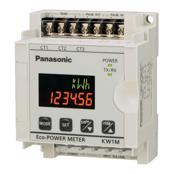
KW1M Eco-POWER METER Chapter 2 Parts Name and Working 2.1 Parts Names ①MODE indicator Lighting when mode setting ②LOCK indicator Lighting while in lock mode ③OP. output indicator Lighting when pulse output ④Mode display Display mode in setting and measurement item with 16-seg With 7-seg ⑤Display each value ・Display each measured value... -
Page 12: Chapter 3 Display Of Each Value
KW1M Eco-POWER METER Chapter 3 Display of each Value 3.1 Working of Monitor Display 【Power Monitoring Mode Display】 Integrated electric power ↓<ITEM> Instantaneous electric power ↓<ITEM> Current S-current → → R-current T-current *3 *1 <SHIFT> <SHIFT> Press <SHIFT> to shift R-A → S-A → T-A → R-A→・・・ ↓<ITEM>... -
Page 13: Power Monitoring Mode
KW1M Eco-POWER METER 3.2 Power Monitoring mode (Sample image is AKW1111. AKW1110 displays same.) Power on the unit and it displays the integrated electric power. 3.2.1 Integrated electric power Sample Integrated active power (kWh) Integrated active power (MWh) ・Integrated electric power is measured and displayed from 0.00kWh to 9999.99MWh. ・The decimal point is changed automatically. -
Page 14: Current
KW1M Eco-POWER METER 3.2.3 Current ・Press <ITEM>key to display the current value of the load. ・Press <SHIFT>key to change R-current and S-current. *Before start measuring, select phase and wire system according to the measured load. When it sets wrong, it doesn’t measure correctly. (Refer to the explanation of setting mode.) Sample R-current (A) S-current (A) *... -
Page 15: Electricity Charge
KW1M Eco-POWER METER ・When input voltage is under 5% of rating, it displays “0.0” and doesn’t measure. (“Under 5%” means the value getting from this calculation “rated voltage 200(400) x 0.05 x VT ratio”.) ‐ ‐ ‐ ‐ ‐ ‐ ・When input voltage exceeds 150%F.S. -
Page 16: Power Factor *Only Akw1111
KW1M Eco-POWER METER 3.2.7 Power factor *only AKW1111 It displays power factor of the load. ・Press <ITEM>key to display the loads’ power factor. Sample Lagging phase Leading phase ・How to calculate power factor Eco-POWER METER displays power factor by calculating as below. Instantaneous electric power PF=... -
Page 17: Counter *Only Akw1111
KW1M Eco-POWER METER *Current flow of CT1 HM-A CUTA Ratio of load current[%] Measured as OFF-h Measured as ON-h *After reaching the full scale (99999.9h), the value reverts to 0.0h but continues to measure. Current Full scale 99999.9h ON-time 0.0h OFF-time 0.0h How to Reset ON/OFF-time... -
Page 18: Other Indication
KW1M Eco-POWER METER 3.3 Other indication 3.3.1 Power On indication Power indicator turns on when the unit power on. POWER indicator Even if the display turns off, the power indicator is lighting while a current flows to the unit. (Refer to Mode 4 setting.) 3.3.2 Indication while communication TX/RX indicator is blinking while Eco-POWER METER is under communication. -
Page 19: Chapter 4 Setting
KW1M Eco-POWER METER Chapter 4 Setting 4.1 Operation procedure AKW1111 (400VAC applicable type) ・MODE1: for power measurement ・MODE2: for pulse measurement ・MODE3: for serial communication(RS-485) ・MODE4: Setting for optional functions Monitor <MODE> ( 1 ) ( 2 ) ( 3 ) ( 4 ) <SET>... -
Page 20: Akw1110
KW1M Eco-POWER METER 4.2 Operation procedure AKW1110 ・MODE1: Setting for power measurement ・MODE3: Setting for serial communication(RS-485) ・MODE4: Setting for optional functions Monitor <MODE> (MODE 1) (MODE 3) (MODE 4) <SET> <SET> <SET> Phase/Wire system Protocol setting mode Auto-off setting mode setting mode PROT SYST... -
Page 21: Setting Mode Explanation
KW1M Eco-POWER METER 4.3 Setting Mode Explanation ■The value with under line is initial setting among each setting value. ☆Set before measurement. 4.3.1 MODE1 (Mode for setting each parameter for power measurement.) Phase/Wire system setting mode SYST Mode defines phase and wire system to measure. ・Select from Single-phase 2-wire / Single-phase 3-wire / Three-phase 3-wire / Three-phase 4-wire. - Page 22 KW1M Eco-POWER METER Unit for pulse output setting mode PL-P Mode defines unit used for pulse output. It defines the unit of integrated electric power for 1-pulse output. ・Select from 0.001/0.01/0.1/1/10/100kWh /AL-P/AL-C/AL-S/Cnt. *“AL-S” and “Cnt” are only for AKW1111. When one of the “0.001/0.01/0.1/1/10/100” [kWh] is set, one pulse is output at reaching the setting value.
- Page 23 KW1M Eco-POWER METER Mode1 Setting flow chart Monitor ↓<MODE> (MODE 1 Lighting) ↓ <SET> Phase/Wire system setting mode Press <ITEM/△><SHIFT/▽> to change Phase/Wire system. System is selected from Single-phase 2-wire ⇔ Single-phase 3-wire ⇔ Three-phase 3-wire ⇔ Three-phase 4-wire. → <SET>...
- Page 24 KW1M Eco-POWER METER Current for time measurement Cutoff current setting mode Setting mode Enter ratio of current for time Enter cutoff current ratio using measurement using <ITEM/△> <ITEM/△> <SHIFT/▽>. If you don’t measure the current under <SHIFT/▽>. 10.0%F.S, set to “ 10.0 ”. If you measure the current over 50.0%F.S., set to “...
-
Page 25: Mode2 * Only Akw1111 (400Vac Applicable Type)
KW1M Eco-POWER METER Preset value setting mode Enter preset value to output using <ITEM/△><SHIFT/▽>. ( 0 ~ 999999) → *It is only when “Cnt” is selected on unit for pulse output <SET> setting mode. Electricity charge setting mode Conversion factor setting mode Enter the rate per 1kWh using Enter the conversion factor per 1kWh using <ITEM/△><SHIFT/▽>. -
Page 26: Mode3
KW1M Eco-POWER METER 4.3.3 MODE3 (Mode for setting of each parameter for serial communication) Protocol setting mode PROT Mode defines communication protocol of main unit via serial communication (RS485). ・Select from MEWTOCOL / MODBUS(RTU). Station number setting mode Mode defines an individual station no. for each unit when two or more units communicate via serial communication (RS485). - Page 27 KW1M Eco-POWER METER Transmission speed setting mode Press <ITEM/△><SHIFT/▽> to change transmission speed. Transmission speed is selected from 19200 ⇔ 38400 ⇔ 2400 ⇔ 4800 ⇔ 9600. 19200bps 38400bps 2400bps → <SET> 4800bps 9600bps Transmission format setting mode Press <ITEM/△><SHIFT/▽> to change transmission format (Data length / Parity). Transmission format is selected from 8bit-o ⇔...
-
Page 28: Mode4
KW1M Eco-POWER METER 4.3.4 MODE4 (Mode for setting of each parameter for optional function) Auto-off setting mode Display LCD turns off automatically when there is no key operation for a long time. ・Off time can be set the range of 0 to 99min. “0”... -
Page 29: Chapter 5 Various Functions
KW1M Eco-POWER METER Chapter 5 Various Functions LOCK indicator 5.1 LOCK mode It is the mode makes all keys unable. Use when you want to fix one of the measurement displays (For all displays). In this mode, you can not input by any keys. When you press <SET>key continuously for about 3sec., the “LOCK”... -
Page 30: Counter Function *Only Akw1111 (400Vac Applicable Type)
KW1M Eco-POWER METER 5.3 Counter function *only AKW1111 (400VAC applicable type) 5.3.1 Operation mode Maintain output hold count HOLD [Output] [Counting] possible [Addition] ・・・ n: Preset value (1) Output control is maintained after count-up completion and until reset. However counting is possible despite of count-up completion. -
Page 31: Chapter 6 Wiring
KW1M Eco-POWER METER Chapter 6 Wiring 6.1 AKW1111 (400V AC applicable type) Be sure to wire correctly according to the terminal arrangement and wiring diagrams. After completing wiring, be sure to attach the terminal cover for safety reasons. 6.1.1 Terminal arrangement M3 Screw Function Screw... - Page 32 KW1M Eco-POWER METER Single-phase three-wire / Three-phase three-wire system *Two current transformers are required. Do not wire ⑥ terminals. They are connected internal. Three-phase four-wire system *Three current transformers are required. ◆When measuring a load with exceed input voltage VT (Voltage transformer) is needed when you measure a load with over rated input voltage (440V). Use commercial VT, those secondary rating is 110V.
-
Page 33: Akw1110
KW1M Eco-POWER METER 6.2 AKW1110 Be sure to wire correctly according to the terminal arrangement and wiring diagrams. After completing wiring, be sure to attach the terminal cover for safety reasons. 6.2.1 Terminal arrangement Function ① Power supply ② ③ N.C. - Page 34 KW1M Eco-POWER METER Single-phase three-wire / Three-phase three-wire system *Two current transformers are required. ◆When measuring a load with exceed input voltage VT (Voltage transformer) is needed when you measure a load with over rated input voltage (220V). Use commercial VT, those secondary rating is 110V. Grounding the secondary side of VT (Voltage transformer) and CT (Current transformer) is not necessary with low-voltage circuit.
-
Page 35: Caution For Wiring
KW1M Eco-POWER METER 6.3 Caution for Wiring 1) Terminal fastening torque should be 0.5 to 0.6N・m for M3 screw and should be 1.0N・m for M3.5 screw. In case of using a crimping terminal, use it with insulating sleeve applicable to M3 screw or M3.5 screw. -
Page 36: How To Attach The Current Transformer (Ct)
KW1M Eco-POWER METER 6.4 How to attach the Current Transformer (CT) ・Using all CTs should be the same. ・When connecting CT, connect the secondary side to the terminal of the main unit first, and after that wire the primary side to a load electric wire. The CT has polarity. Wire correctly according to the K and L marks. -
Page 37: For Output Connection
KW1M Eco-POWER METER 6.5 For Output connection Since the transistor output is insulated from the internal circuit by a photo-coupler, it can be used both as a NPN output and PNP (equal value) output. Eco-POWER METER Eco-POWER METER NPN output Pulse (+) PNP output Pulse (+) -
Page 38: Chapter 7 Communication
KW1M Eco-POWER METER Chapter 7 Communication 7.1 Communication Procedures Communication starts with command transmission from the host computer (hereafter Master) and ends with the response of Eco-POWER METER (hereafter Slave). Master Slave Command • Response with data When master sends reading command, slave responds with the Data corresponding set value or current status. -
Page 39: Mewtocol Communication
KW1M Eco-POWER METER 7.3 MEWTOCOL Communication 7.3.1 Overview of MEWTOCOL-COM (RS485) ◆Command and response functions The computer sends commands (instructions) to Eco-POWER METER, and receives responses in return. This enables the computer and Eco-POWER METER to converse with each other, so that various kinds of information can be obtained and provided. -
Page 40: Data Register List
KW1M Eco-POWER METER 7.3.2 Data Register List <AKW1111 (400AC applicable type)> Data register Name Unit Kind of data Range DT00054 Rate (CHG) 0.01 0 to 9999 Unsigned 16bit Conversion factor 0.001 DT00055 0 to 9999 Unsigned 16bit (CO2) kg-CO Rated A DT00060 CT type 5 types: 5,50,100,250,400... -
Page 41: Data Register List
KW1M Eco-POWER METER 7.3.3 Data Register List <AKW1110> Data register Name Unit Kind of data Range DT00054 Rate (CHG) 0.01 0 to 9999 Unsigned 16bit Conversion factor 0.001 DT00055 0 to 9999 Unsigned 16bit (CO2) kg-CO Rated A DT00060 CT type 5 types: 5,50,100,250,400 Unsigned 16bit (rms) -
Page 42: Error Codes
KW1M Eco-POWER METER 7.3.4 Error Codes ◇Basic procedure errors Error code Error name Explanation Bcc error ・A Bcc error occurred in the command data. ・A command message was sent that does not fit the transmission Format error format. No support error ・A command was sent that is not supported. - Page 43 KW1M Eco-POWER METER ◆[MD]: Register or Reset data monitored (Registers the data to be monitored.) *Up to 16 points can be registered for one unit. ◇Command (Register) Data specification ① Data specification Word No. Word No. Destination % # 5 characters 5 characters ×10 ×10...
-
Page 44: Modbus (Rtu) Communication
KW1M Eco-POWER METER 7.4 MODBUS (RTU) Communication 7.4.1 Overview of MODBUS (RTU) ◆8-bit binary data in command is transmitted as it is. Data format Start bit : 1 bit Data bit : 8 bits *7bits is not available. Parity : No parity, Even parity, Odd parity Selectable Stop bit : 1 bit (Fixed) Error detection... -
Page 45: Data Register List
KW1M Eco-POWER METER 7.4.2 Data Register List <AKW1111 (400VAC applicable type)> Data item Range: Hexadecimal MODBUS Name Unit Kind of date (Range: Decimal) Function code (MEWTOCOL) 0036H Rate (CHG) 0H to 270FH (0 to 9999) 0.01 Unsigned 16bit 03H/06H/10H (DT00054) Conversion factor 0037H 0.001... - Page 46 KW1M Eco-POWER METER Data item Range: Hexadecimal MODBUS Name Unit Kind of date (Range: Decimal) Function code (MEWTOCOL) 0096H 0H to F423FH (DT00150) Load ON-time 0.1h Unsigned 16bit 03H/06H/10H (0 to 999999) 0097H (DT00151) 0098H 0H to F423FH (DT00152) Load OFF-time 0.1h Unsigned 16bit 03H/06H/10H...
-
Page 47: Data Register List
KW1M Eco-POWER METER 7.4.3 Data Register List <AKW1110> Data item Range: Hexadecimal MODBUS Name Unit Kind of date (Range: Decimal) Function code (MEWTOCOL) 0036H Rate (CHG) 0H to 270FH (0 to 9999) 0.01 Unsigned 16bit 03H/06H/10H (DT00054) 0037H Conversion factor 0.001 0H to 270FH (0 to 9999) Unsigned 16bit... - Page 48 KW1M Eco-POWER METER Data item Range: Hexadecimal MODBUS Name Unit Kind of date (Range: Decimal) Function code (MEWTOCOL) 00B0H Instantaneous (DT00176) 0H to F423FH (0 to 999999) 0.01kW Unsigned 32bit 00B1H electric power (DT00177) note1) Even if it commands to write (06H.10H) to non-existent data address, slave response with acknowledgement.
- Page 49 KW1M Eco-POWER METER ② Setting electricity rate (0036H) of address 1 (When rate is set to 20.00(2000) [07D0H]) ・Command Slave Function Data item Number of Error check 3.5 idle 3.5 idle address code data CRC-16 characters characters (01H) (06H) (0036H) (07D0H) (6A68H) ←character...
-
Page 50: Chapter 8 Specifications
KW1M Eco-POWER METER Chapter 8 Specifications 8.1 Main unit Item AKW1111 AKW1110 Rated operating voltage 100-240V AC Rated frequency 50/60Hz common Rated power consumption 8VA (240VAC at 25℃) 6VA (240VAC at 25℃) Inrush current Max. 30A (240VAC at 25℃) Allowable operating 85-264V AC (85% to 110% of rated operating voltage) voltage range Allowable momentary... -
Page 51: Pulse Input *Only Akw1111 (400Vac Applicable Type)
KW1M Eco-POWER METER <Using the dedicated CT> ・5A/50A/100A/250A/400A (Select with setting mode) <Using a commercial CT with the secondary side current 5A> Input Primary side ・1 to 4000A (Set with setting mode) current rating *Use a commercial CT with secondary side current of 5A when measure 400A or more. -
Page 52: Output Specifications
KW1M Eco-POWER METER 8.3 Output Specifications 8.3.1 Pulse output (Transistor output) AKW1111 AKW1110 Number of output point 1 point Insulation method Optical coupler Output type Open collector Output capacity 100mA 30V DC Pulse width approx. 100ms ON state voltage drop 1.5V or less OFF state leakage current 100μA or less... -
Page 53: Dedicated Current Transformer Specifications
KW1M Eco-POWER METER 8.5 Dedicated Current Transformer Specifications Model No AKW4801C AKW4802C AKW4803C AKW4804C Primary side rated current 5A / 50A 100A 250A 400A Secondary side rated 1.67mA / 16.7mA 33.3mA 125mA 200mA current Winding (Turn) 3000 3000 2000 2000 Ratio error ±2.0% F.S. -
Page 54: Chapter 9 Mounting
KW1M Eco-POWER METER Chapter 9 Mounting 9.1 Dimensions 9.1.1 AKW1111 Main unit 9.1.2 AKW1110 Main unit... -
Page 55: Dedicated Ct
KW1M Eco-POWER METER Panel cutout 9.1.3 Dedicated CT (unit: mm) ◆For 5A/50A (AKW4801C) (tolerance: ±1.0) - Page 56 KW1M Eco-POWER METER ◆For 100A (AKW4802C) ◆For 250A (AKW4803C)
-
Page 57: How To Mount To Din Rail
KW1M Eco-POWER METER ◆For 400A (AKW4804C) ◆Attached trunk cable (common) 9.2 How to mount to DIN rail (1) Hook “A” of main unit on the upper side of DIN rail. (2) Making “A” part as a support fit the bottom side of main unit to DIN rail. (3) It will be completely fixed to DIN rail with a “click”... -
Page 58: Chapter 10 Q&A
KW1M Eco-POWER METER Chapter 10 Q&A ■Hardware I’d like to measure by Eco-POWER METER. Measured load is 50 to 60A in normal operation. But the inrush current is 130 to 140 A. Which CT is selected? (100A or 250A) Select 100ACT. Stable current more than 1 second is necessary to measure. - Page 59 KW1M Eco-POWER METER Revision History Issue Date Manual no. Content of revision January, 2010 ARCT1F473E First edition...