Table of Contents
Advertisement
Advertisement
Table of Contents

Related Manuals for Siemens SINAMICS IOP-2


Summary of Contents for Siemens SINAMICS IOP-2
- Page 3 Changes in this manual Fundamental safety instructions SINAMICS Safety notes Overview Intelligent Operating Panel 2 (IOP-2) Installation Setup Menu Operating Instructions Control menu Menu Options Technical data Edition 06/2020, Firmware IOP-2 V2.6 06/2020, FW V2.6 A5E39549448B AH...
- Page 4 Note the following: WARNING Siemens products may only be used for the applications described in the catalog and in the relevant technical documentation. If products and components from other manufacturers are used, these must be recommended or approved by Siemens. Proper transport, storage, installation, assembly, commissioning, operation and maintenance are required to ensure that the products operate safely and without any problems.
-
Page 5: Table Of Contents
Table of contents Changes in this manual ......................... 5 Fundamental safety instructions ......................7 General safety instructions ....................7 Warranty and liability for application examples ..............7 Security information ......................7 Safety notes ............................9 Warnings and cautions ......................9 Overview .............................. - Page 6 Table of contents Parameters ........................51 Up/Download ........................54 Support ..........................59 Customer parameter sets ....................61 Extras Menu ........................65 Options ..............................71 Door mounting kit ......................71 Hand-held device ....................... 74 Technical data............................79 10.1 Technical specifications ..................... 79 Index ..............................
-
Page 7: Changes In This Manual
Changes in this manual Changes to this manual - Edition 06/2020 Listed below and the specific changes that have been incorporated in this new version of the IOP-2 Operating Instructions. Changes • New topic: Command Line Interface (CLI). Up/Download (Page 54). Intelligent Operating Panel 2 (IOP-2) Operating Instructions, 06/2020, FW V2.6, A5E39549448B AH... - Page 8 Changes in this manual Intelligent Operating Panel 2 (IOP-2) Operating Instructions, 06/2020, FW V2.6, A5E39549448B AH...
-
Page 9: Fundamental Safety Instructions
In order to protect plants, systems, machines and networks against cyber threats, it is necessary to implement – and continuously maintain – a holistic, state-of-the-art industrial security concept. Siemens’ products and solutions constitute one element of such a concept. Intelligent Operating Panel 2 (IOP-2) - Page 10 Siemens’ products and solutions undergo continuous development to make them more secure. Siemens strongly recommends that product updates are applied as soon as they are available and that the latest product versions are used. Use of product versions that are no longer supported, and failure to apply the latest updates may increase customer’s exposure to...
-
Page 11: Safety Notes
Safety notes Warnings and cautions Warnings and cautions DANGER Ensuring a safe and stable state During commissioning of the converter it is essential to ensure that the system is in a safe and stable state, as some commissioning processes have the potential to start the motor. Therefore it is important to secure any loads and ensure that should the motor start, no potentially dangerous conditions exist. - Page 12 Safety notes 3.1 Warnings and cautions WARNING Risk of death due to software manipulation when using exchangeable storage media Storing the parameterization (incl. Safety Integrated parameterization) on exchangeable storage media carries the risk that the original parameterization (with Safety Integrated) will be overwritten, for example, by the IOP-2 of another drive without Safety Integrated.
-
Page 13: Overview
Overview Introduction Compatibility The Intelligent Operator Panel 2 (IOP-2) has been designed to enhance the interface and communications capabilities of SINAMICS Inverters. The IOP-2 connects to the Inverter through an RS232 interface. It has been designed to automatically recognize the following devices from the SINAMICS range: •... -
Page 14: Layout And Functions
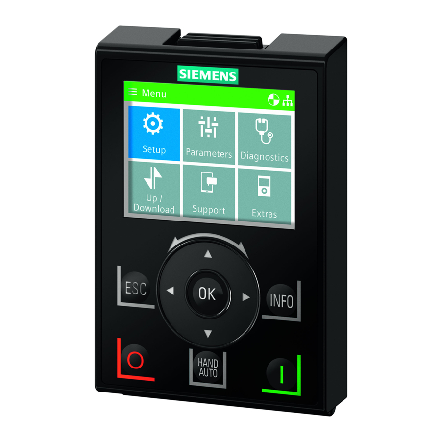
Overview 4.2 Layout and functions For information on firmware and language upgrades, please see Upgrading the IOP-2 firmware (Page 25). Note IOP functional support • Drives with SINAMICS firmware 4.7 SP3 or above will support the new commission processes of "Quick Startup" and "Advanced Startup". •... - Page 15 Overview 4.2 Layout and functions The IOP-2 is operated by using a Sensor Control Field and five additional buttons. The specific functions of the Sensor Control Field and buttons are shown in the table below. Table 4- 1 Function of the IOP-2 controls Function The Sensor Control Field has the following functions: •...
-
Page 16: Screen Icons
Overview 4.3 Screen icons Function The INFO key has the following functions: • Displays additional information for the currently selected item. • Pressing the INFO key again will display the previous screen. • Pressing the INFO key during power-up of the IOP-2 will place the IOP-2 in DEMO mode. To exit DEMO mode, power-cycle the IOP-2. - Page 17 Overview 4.3 Screen icons Function Icon Remarks Inverter status Icon rotates when the motor is running Fault pending Alarm pending Saving to RAM Indicates that all recent changes to parameters have been saved in RAM only. In the event of a power failure, then all recent changes saved to RAM will be lost.
-
Page 18: Menu Structure
Overview 4.4 Menu structure Menu structure Overview The Menu structure of the IOP-2 is shown in the figure below. Figure 4-3 IOP-2 menu structure Intelligent Operating Panel 2 (IOP-2) Operating Instructions, 06/2020, FW V2.6, A5E39549448B AH... -
Page 19: Installation
Installation Fitting the IOP-2 Fitting the IOP-2 to the Control Unit Note IOP-2 power supply The IOP-2 has no internal power supply and derives its power directly from the Control Unit of the converter through the RS232 interface. The IOP-2 can also be connected to a PC and derives its power through the USB connection. -
Page 20: Initial Set-Up
Installation 5.2 Initial set-up Initial set-up Initial set-up sequence Once the IOP-2 is fitted and powered-up it will automatically detect the type of Control Unit and Power Module to which it has been fitted. On first-time use, the IOP-2 automatically displays the option to select the default language and allow the time and date to be set (if the Control Unit to which the IOP-2 is fitted has a real-time clock). - Page 21 Installation 5.2 Initial set-up Wait until the factory reset is Change or confirm settings Status screen on completion finished Note The IOP-2 is delivered with all available languages and the Quick Startup and Advanced Startup setups. For information on Firmware upgrades, please see Upgrading the IOP-2 firmware (Page 25).
- Page 22 Installation 5.2 Initial set-up Select language Select required language Press and hold down ESC for Status Screen All available languages are delivered with the IOP-2. Setting time and date When the IOP-2 is first fitted to a Control Unit, which has a real-time clock, it will automatically display the time and date screen.
- Page 23 Installation 5.2 Initial set-up The settings for time are normally done on the Control Unit if it has a Real-time Clock (RTC). If the Inverter has an RTC the IOP-2 will take its settings from the Control Unit. Lighting duration To set the length of time that the display remains lit, the following actions should be performed: Select Menu...
-
Page 24: Changing The Status Screens
Installation 5.3 Changing the Status screens Display backlight To change the intensity of the backlight, the following actions should be performed: Select Menu Select Extras Select Panel settings Select Display backlight Select display backlight level Press and hold down ESC for Status Screen The display backlight setting will be automatically changed to the "Low"... - Page 25 Installation 5.3 Changing the Status screens Select a different status screen To select a different status screen the following procedure should be performed: 1. When the status screen is displayed, use the UP arrow key to enter the screen selected mode.
-
Page 26: User Definable Labels On Status Screen
Installation 5.4 User definable labels on status screen Figure 5-2 Selecting and modifying the IOP-2 status screens User definable labels on status screen User definable labels User defined labels allow the user to customize the labels that appear on the status screen of the IOP-2. -
Page 27: Upgrading The Iop-2 Firmware
Installation 5.5 Upgrading the IOP-2 firmware Storage" mode to access the files on the IOP-2.The files are basic text files and can be opened with any basic text editor. The default label names are "default", when the labels have the "default"... - Page 28 The English language file is essential to the correct functioning of the IOP-2 and therefore cannot be deleted. Only IOP-2 firmware update packages obtained through the Siemens Service and Support website at the following link should be used: IOP-2 firmware download: IOP-2 Firmware upgrade (https://support.industry.siemens.com/cs/ww/en/view/109762019)
-
Page 29: Setup Menu
Setup Menu Overview The IOP-2 Setups are question-driven environment that assist the user to set-up various functions and applications of the converter. WARNING Motor Identification (Motor ID) function will run automatically Using the "Standard Drive Control" or "Dynamic Drive Control" in Quick Startup, the Motor ID function, if selected, is activated at the end of the commissioning squenence. -
Page 30: Example Setups
Setup Menu 6.1 Example Setups Example Setups Overview of Setup The following example of how Setup work on the IOP-2 are purely for demonstration purpose only. CAUTION Before setting up an application Prior to using Setup, it is essential that the user's Control Unit and Power Module have been installed and wired correctly, in accordance with the requirements of the user's application. - Page 31 • Application Setup: This allows the user to configure the application specific functions of the converter. For more detailed information of the application classes, see the document at the link below: Application classes (https://support.industry.siemens.com/cs/ww/en/view/109480663) Control Types Standard Drive Control • Standard Drive Control is preset for the Power Modules PM240, PM240-2 and G120C in frame sizes FSA-C.
- Page 32 Setup Menu 6.1 Example Setups Dynamic Drive Control • Dynamic Drive Control is preset for the Power Modules PM240, PM240-2 and PM330 in frame sizes ≥ FSD. This application class can, for example, be used for the following applications: – Pumps and compressors with displacement machine –...
-
Page 33: Quick Startup With The Iop-2
Setup Menu 6.1 Example Setups Info Screens Info Screens (Information Screens) are accessed with a press of the INFO button. There may be multiple INFO screens and these you can navigated between each screen using the arrow keys. Figure 6-1 Using the INFO button 6.1.1 Quick Startup with the IOP-2... - Page 34 Setup Menu 6.1 Example Setups Select Setup Select Quick Startup Select Factory Reset (yes or Factory Reset begins Select Motor Standard Select mains frequency and units Select Motor Type Select Input Mode Enter Motor Data or Motor Code Select Supply Voltage Enter Supply Voltage from Select Motor Current rating label...
- Page 35 Setup Menu 6.1 Example Setups Enter Motor Current from Select Motor Power Enter Motor Power from rating label rating label Select Motor Speed Enter Motor Speed from Select Motor Voltage rating label Enter Motor Voltage from Select Motor Frequency Enter Motor Frequency rating label Select Min.
- Page 36 Setup Menu 6.1 Example Setups Enter the required Max. Freq. Select Ramp-up Time Enter required Ramp-up Time Select Ramp-down Time Enter required Ramp-down Select I/O Setup Time Select the required Macro Save the Settings Saving Settings in progress Settings have been saved Motor ID ran on next ON Setup up completed command...
-
Page 37: Advanced Startup With The Iop-2
Setup Menu 6.1 Example Setups 6.1.2 Advanced Startup with the IOP-2 Advanced Startup overview Advanced Startup is a commissioning process for all application which provides a high degree of flexibility when dealing with the converter settings. The provided settings allow an optimized adaption of the converter to the target application. - Page 38 Setup Menu 6.1 Example Setups Advanced Startup Menu This screen lists all the advanced settings that are available for the user to modify for their specific application. Drive Information This screen provides general information concerning the used converter configuration (Power Module, Control Unit and the Intelligent Operator Panel IOP-2).
- Page 39 Setup Menu 6.1 Example Setups Motor Data The motor data stored here corresponds to the 4-pole SIEMENS standard motor with the same converter power. For dynamic applications and when other OEM motors are in operation, adaptation of the settings will need to be made.
- Page 40 Setup Menu 6.1 Example Setups Application Setup This screen allows the applications specific functions to be configured. When "Application Setup" is selected, the user is presented with some default applications functions, depending on the type of Control Unit that is being used. The user can setup their own list of functions using the "Adjust function list"...
-
Page 41: Control Menu
Control menu Overview The Control menu allows the user to change the following settings in real-time: • Setpoint • Reverse • Jog • Custom Hand mode • Startup in Hand mode • Hand/Auto disable The control menu is accessed from the menu at the bottom-centre of the Status screen, as shown below. -
Page 42: Setpoint
Control menu 7.1 Setpoint Setpoint Setting the Setpoint The setpoint value determines the speed at which the motor runs as a percentage of its full range of motion. To change the setpoint, the following actions should be performed: Select Control Select Setpoint Use Touch-wheel to set the Setpoint... -
Page 43: Jog
Control menu 7.3 Jog Setting Jog The Jog function, when selected will allow the motor to be manually rotated by a pre- determined value with each press of . If is pressed continuously, the motor will rotate continuously until is released. To enable or disable the Jog function, the following actions should be performed: Select Control Select Jog... - Page 44 Control menu 7.4 Custom Hand mode An example of setting up the custom hand mode is given in the instructions below. Table 7- 1 Interconnection inputs for Status Word 1 in Custom Hand mode Standard interconnection r8540 STW 1 from IOP-2 Binector Inputs (BI) p8542 Effective STW1 in Custom Hand...
-
Page 45: Startup In Hand Mode
Control menu 7.5 Startup in Hand mode Select Control Parameter Select required function Select source of command signal Select the input that will Select Setpoint Parameter Select the setpoint signal receive command signal source Select the input to receive the setpoint signal Once the setpoint signal input has been selected, the IOP-2 will return to the Setpoint selection screen then press ESC for >3 secs, to return to the status screen. -
Page 46: Hand/Auto Disable
Control menu 7.6 HAND/AUTO disable Setting up Startup in Hand mode example Select Control Select Startup in Hand Mode Set the required speed setpoint as a percentage value The IOP-2 will automatically return to the Control menu and show that "Startup in Hand Mode"... - Page 47 Control menu 7.6 HAND/AUTO disable Select On: Hand/Auto from Enter password again or Select signal source PLC or DI create a new password Select input to receive control Press ESC to return to Control signal Menu The HAND/AUTO button is now disabled and local control of the IOP-2 cannot be activated by the HAND/AUTO button.
- Page 48 Control menu 7.6 HAND/AUTO disable Intelligent Operating Panel 2 (IOP-2) Operating Instructions, 06/2020, FW V2.6, A5E39549448B AH...
-
Page 49: Menu
Menu Menu overview Overview WARNING Protection of project data files from unauthorized usage Transportation of project data files have to be secured by technical means, for example, encrypted/signed emails, encrypted/signed USB-sticks etc., especially in the public internet. Project data files have to be stored with restricted access within the OEM/end customer area, for example, access restrictions to SharePoints, databases, etc. -
Page 50: Diagnostics
Menu 8.2 Diagnostics Diagnostics Diagnostics menu When the diagnostic function is selected the following options are presented: • Active faults/alarms • History • Identification/Maintenance • I/O status • Communications status • I/O simulation • Drive enables Active faults/alarms When this option is selected the screen will display any active faults and alarms that have not yet been acknowledged. - Page 51 Menu 8.2 Diagnostics I/O status This option displays a list of the digital and analog inputs and outputs of the converter and their current status. This is an information screen and cannot be changed. Pressing ESC will return the display to the previous menu. In the example shown opposite, the status of the digital inputs are displayed.
- Page 52 Menu 8.2 Diagnostics The IOP-2 simulation screen allows digital and analog IOs to be simulated without the requirement for external signals. These features are of great benefit during commissioning and fault finding, as the user can quickly simulate a situation without using wires, tools and external equipment.
-
Page 53: Parameters
Menu 8.3 Parameters Parameters Parameter menu For information on IOP-2 compatibility, see Introduction (Page 11). The parameter menu allows the user extensive functionality and access to all the converter parameters. When this option is selected the user is given the opportunity to perform parameter orientated functions grouped in the following manner: •... - Page 54 Menu 8.3 Parameters Saving & reset This option allows the user access to all the parameters regarding the saving and reset functions of the converter. Each parameter displays it's currently set value and these can be modified if required. System information This screen displays all the parameters that contain system information regarding the converter.
- Page 55 Menu 8.3 Parameters Search by number This option allows the user to search for a specific parameter number. If the parameter number does not exist, the screen will display a choice between "Select a new number" or "Go to the nearest parameter number".
-
Page 56: Up/Download
If safety parameters are to be downloaded a function test of the safety functions has to be performed. Please refer to the "Safety Integrated Function Manual" which can be found at the hyperlink below: Safety Integrated Function Manual (http://support.automation.siemens.com/WW/view/en/50736819) Intelligent Operating Panel 2 (IOP-2) Operating Instructions, 06/2020, FW V2.6, A5E39549448B AH... - Page 57 Menu 8.4 Up/Download Using the IOP-2 The IOP-2 must be handled with particular care for all SINAMICS devices that use an IOP-2 so that no malicious software or erroneous parameterizations are spread between different commissioning PCs or inverters. WARNING Risk of death due to software manipulation when using exchangeable storage media Storing files onto exchangeable storage media amounts to an increased risk of infection of the commissioning PCs, e.g.
- Page 58 Menu 8.4 Up/Download The naming of the file follows the normal conventions and is restricted to only the ASCII character set, but it is suggested that the file name should be in lower case with only numbers and letters without spaces, followed by the correct file extension. List of commands Command Format...
- Page 59 Menu 8.4 Up/Download 4. When the download is completed, the "Parameter transfer completed" with be displayed. Press OK to return to the main download screen. Safety parameter download 1. If Safety parameters are contained within the CLI file, the user will be prompted to enter the safety password.
- Page 60 Menu 8.4 Up/Download Error messages WARNING Unexpected behavior If the download process is canceled for any reason, all parameters that have been overwritten by the download process will remain changed. The drive may be in an unknown state and its behavior may not be as expected. A factory reset should be performed to ensure that the drive is in a known, safe state.
-
Page 61: Support
You can download the necessary Siemens app using the menu item "Download the Siemens App" which will take you to the appropriate Siemens site that will direct the user to the correct site for either Android or iPhone Smartphone platforms. - Page 62 Scan the QR code menu Partner" When the QR code is scanned, the user is taken to the Siemens Industrial support site. After selecting the correct country, region, the user is given the contact details of their Local Service Partner.
-
Page 63: Customer Parameter Sets
Menu 8.6 Customer parameter sets Customer parameter sets Overview Custom parameter sets can now be created and stored on the Intelligent Operator Panel (IOP- The IOP-2 can store up to 255 parameter sets with customized names. The steps to create and store a custom parameter set on the IOP-2 is given in the procedure outlined below. - Page 64 Menu 8.6 Customer parameter sets Using the IOP-2 The IOP-2 must be handled with particular care for all SINAMICS devices that use an IOP-2 so that no malicious software or erroneous parameterizations are spread between different commissioning PCs or inverters. WARNING Risk of death due to software manipulation when using exchangeable storage media Storing files onto exchangeable storage media amounts to an increased risk of infection of...
- Page 65 Menu 8.6 Customer parameter sets The number of available The drive parameter settings The filename of the parameter sets are displayed are uploaded parameter set is displayed Select rename parameter set Select the parameter set to Rename the file using on- be renamed screen keyboard Select return icon to accept...
- Page 66 Menu 8.6 Customer parameter sets WARNING Risk of death due to software manipulation when using exchangeable storage media Storing the parameterization (incl. Safety Integrated parameterization) on exchangeable storage media carries the risk that the original parameterization (with Safety Integrated) will be overwritten, for example, by the IOP-2 of another drive without Safety Integrated.
-
Page 67: Extras Menu
Menu 8.7 Extras Menu 5. Disconnect the IOP-2 from the PC. 6. Connect another IOP-2 and copy the saved parameter sets to the "user/cps" on the new IOP- This procedure can be repeated for any number of IOP-2s. Extras Menu Overview The Extras menu presents a number of options for the configuration of the IOP-2, these are explained in this... - Page 68 Menu 8.7 Extras Menu Default dataset This option allows the user to determine which is the default command dataset when viewing or selecting a new default dataset from the options provided. Note: Some applications require that both command datasets be used at the same time.
- Page 69 Menu 8.7 Extras Menu Panel settings Language This option allows the user to select the language that is used to display information and text on the IOP-2. This option has been previously described in the initial set-up section of this manual. Languages can be added or deleted using the USB connection on the IOP-2 and a PC.
- Page 70 Menu 8.7 Extras Menu Set week DST starts Set day DST starts Set time DST starts Set month DST ends Set week DST ends Set day DST ends Set time DST ends Set date and time IOP-2 returns to previous screen (this may take a few seconds) Operator panel factory reset...
- Page 71 Menu 8.7 Extras Menu Display backlight This option allows the user to change intensity of the display lighting. For details of selecting this function see Initial set-up (Page 18) Lighting duration The backlight display, by default, is set to automatically turn off after 60 seconds from the last key press.
- Page 72 Menu 8.7 Extras Menu Intelligent Operating Panel 2 (IOP-2) Operating Instructions, 06/2020, FW V2.6, A5E39549448B AH...
-
Page 73: Options
Options Door mounting kit Door mounting kit The door mounting kit (DMK) has been designed to allow the IOP, IOP-2 or BOP-2 to be mounted into the door of a cabinet. The Operator Panels (OP), when installed correctly in the door of the cabinet, provide the following IP ratings around the DMK: •... - Page 74 Options 9.1 Door mounting kit Figure 9-2 Fitting Operator Panel DMK (thread-forming screws) CAUTION Thread-forming screws maximum torques Using a torque greater than 1.2 Nm with the thread-forming screws may lead to permanent damage of the threads. The thread-forming screws must be correctly aligned with the holes on the back of the OP;...
- Page 75 Options 9.1 Door mounting kit The depth of the panel or cabinet door should be between 1 mm to 3 mm. The IOP-2 Door Mounting Kit can be ordered using the following order number: 6SL3256-0AP00-0JA0 The DMK contains the following items: •...
-
Page 76: Hand-Held Device
Options 9.2 Hand-held device Hand-held device Hand-held device WARNING Charging unit • The charging unit for the rechargeable batteries is contained within the hand-held device for the sole purpose of charging rechargeable batteries. • The charging unit contained within the hand-held device should not be used with standard "AA"... - Page 77 Options 9.2 Hand-held device Note Battery lifetime With the supplied rechargeable batteries in a fully-charged state they should last for approximately 10 hours; the use of normal "AA" batteries may last considerably less time. Industrial environment The IOP-2 has been designed for use within a Class A Industrial environment only. Disposal of batteries The batteries supplied with the IOP-2 must be disposed of in accordance with local and national environmental policies.
- Page 78 Options 9.2 Hand-held device Note Battery order information The batteries supplied with the IOP-2 Hand-held Kit should be replaced with exactly the same type of batteries. The batteries that have been tested for use with the IOP-2 are given below: Company: GP Batteries Order Number: GP210AAHC The batteries can be ordered from the following website: GP Batteries...
- Page 79 Options 9.2 Hand-held device Fitting the batteries The hand-held device is powered by four 'AA' rechargeable batteries; these batteries are supplied with the hand-held kit. The batteries are fitted as shown in the figure below. Figure 9-4 Installing batteries for handheld kit Intelligent Operating Panel 2 (IOP-2) Operating Instructions, 06/2020, FW V2.6, A5E39549448B AH...
- Page 80 Options 9.2 Hand-held device Intelligent Operating Panel 2 (IOP-2) Operating Instructions, 06/2020, FW V2.6, A5E39549448B AH...
-
Page 81: Technical Data
Technical data 10.1 Technical specifications IOP-2-2 Technical data Table 10- 1 IOP-2 and Door mounting kit specifications Feature IOP-2 only Door mounting kit Protection Depending upon the Control Unit IP rating to a max. of IP55 / UL Type 12 enclosure Dimensions (HxWxD) 106.86 mm x 70 mm x 19.65 mm (Depth... -
Page 83: Index
Index " "config" folder, 64 Extra menu "cps" folder, 64 Drive identity, 65 Panel settings, 67 Extras menu, 65 Active faults/alarms, 48 Advanced Startup, 35 AUTO mode, 13 file structure, 64 Firmware version, 5 functional support, 12 Changed parameters, 53 Changing the status screens, 22 cloning, 54 HAND mode, 13... - Page 84 Index Language selection, 19 Reverse, 40 Lighting duration, 21 Safety Parameters, 54 Macro source selection, 30 saving, 54 Menu, 47 Screen icons Menu Overview, 47 icons, 14 Menu structure, 16 Search by number, 53 Modify the display data, 23 Select a different status screen, 23 My parameters, 53 Sensor Control Field, 13 Setpoint, 40...