Siemens SINAMICS BOP-2 Operating Instructions Manual
Basic operator panel
Hide thumbs
Also See for SINAMICS BOP-2:
- Operating instructions manual (36 pages) ,
- Operating instructions manual (55 pages)

Related Manuals for Siemens SINAMICS BOP-2


Summary of Contents for Siemens SINAMICS BOP-2
- Page 1 SINAMICS BOP-2 Basic Operator Panel 2 Operating Instructions · March 2010 SINAMICS...
- Page 3 Safety notes Overview Installation SINAMICS Monitoring SINAMICS Basic Operator Panel 2 (BOP-2) Control Diagnostics Operating Instructions Parameters Setup Extras Technical data Edition 03/2010 2010-03-01 A5E02778927A AB...
- Page 4 Note the following: WARNING Siemens products may only be used for the applications described in the catalog and in the relevant technical documentation. If products and components from other manufacturers are used, these must be recommended or approved by Siemens. Proper transport, storage, installation, assembly, commissioning, operation and maintenance are required to ensure that the products operate safely and without any problems.
-
Page 5: Table Of Contents
Table of contents Safety notes............................... 7 Overview..............................9 Installation ............................... 15 Monitoring..............................17 Control ..............................19 Diagnostics .............................. 23 Parameters .............................. 29 Setup ............................... 33 Extras ..............................41 Technical data ............................47 Basic Operator Panel 2 (BOP-2) Operating Instructions, 2010-03-01, A5E02778927A AB... -
Page 6: Basic Operator Panel 2 (Bop
Table of contents Basic Operator Panel 2 (BOP-2) Operating Instructions, 2010-03-01, A5E02778927A AB... -
Page 7: Safety Notes
Safety notes Warnings and cautions WARNING • During commissioning of the Inverter it is essential to ensure that the system is in a safe and stable state, as some commissioning processes have the potential to start the motor. Therefore it is important to secure any loads and ensure that should the motor start, no potentially dangerous conditions exist. - Page 8 Safety notes Basic Operator Panel 2 (BOP-2) Operating Instructions, 2010-03-01, A5E02778927A AB...
-
Page 9: Overview
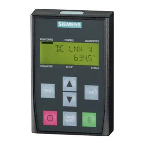
Overview Introduction The Basic Operator Panel 2 (BOP-2) has been designed to enhance the interface and communications capabilities of SINAMICS Inverters. The BOP-2 connects to the Inverter through an RS232 interface. It has been designed to automatically recognise all variants of the following Control Units from the SINAMICS range: ●... - Page 10 Overview Layout and functions The physical layout of the BOP-2 is shown below: Figure 2-1 Layout of the BOP-2 Table 2- 1 Description of BOP-2 physical characteristics Item Description ① Release catch ② LCD screen ③ ESC key ④ Up key ⑤...
-
Page 11: Parameters
Overview Table 2- 2 Function of the BOP-2 controls Function The OK key has the following functions: When navigating through the menus, pressing the OK key confirms selection of a menu item. • When working with parameters, pressing the OK key allows the parameter to be modified. Pressing the OK •... - Page 12 Overview Note Reaction to change between HAND and AUTO mode When changing from HAND to AUTO mode the Inverter will react in the following way: • If the ON signal is active the new setpoint will become active and the Inverter will automatically ramp the motor to the new setpoint after the change of mode.
-
Page 13: Setup
Overview Menu structure The BOP-2 is a menu-driven device and has the following menu structure: MONITOR CONTROL DIAGNOS PARAMS SETUP EXTRAS SP 1500. 0 NO HAND- ACKN ALL STANDARD RESET DRVRESET FILTER 1500. 0 VOLT OUT SETPOINT FAULTS EXPERT CTRL MOD RAM ->... - Page 14 Overview Note Menu structure and functionality The actual menu structure and functionality of the BOP-2 is influenced by the following factors: • The software version and type of Control Unit to which the BOP-2 has been fitted. • The firmware and software version of the BOP-2. Basic Operator Panel 2 (BOP-2) Operating Instructions, 2010-03-01, A5E02778927A AB...
-
Page 15: Installation
Installation Fitting the BOP-2 to the Control Unit Note BOP-2 power supply The BOP-2 has no internal power supply and derives its power directly from the Control Unit of the Inverter through the RS232 interface. Any cloned data stored on the BOP-2 will be saved to its non-volatile memory which does not require power to retain its data. -
Page 16: Monitoring
On startup the BOP-2 will display the company name and MONITORING MONITORING CONTROL CONTROL DIAGNOSTICS DIAGNOSTICS the class of Operator Panel. SIEMENS BOP-2 PARAMETER PARAMETER SETUP SETUP EXTRAS EXTRAS The BOP-2 will then display the current software version of... -
Page 17: Monitoring
Monitoring Overview The Monitor menu allows the user to easily access a variety of screens which display the actual status of the Inverter/motor system. The menu is selected by using the keys to MONITORING MONITORING CONTROL CONTROL DIAGNOSTICS DIAGNOSTICS move the menu bar to the required menu. MONITOR Pressing will confirm the selection and display the top... - Page 18 Monitoring The current output screen shows the actual Inverter MONITORING MONITORING CONTROL CONTROL DIAGNOSTICS DIAGNOSTICS current output to the motor. CURR OUT 10. 0 PARAMETER PARAMETER SETUP SETUP EXTRAS EXTRAS This screen shows the actual frequency (in Hz) at which MONITORING MONITORING CONTROL...
-
Page 19: Control
Control Introduction The control menu allows the user to access the following functions of the Inverter: ● Setpoint ● Jog ● Reverse The menu is selected by using the keys to MONITORING MONITORING CONTROL CONTROL DIAGNOSTICS DIAGNOSTICS move the menu bar to the required menu. CONTROL Pressing will confirm the selection and display the top... - Page 20 Control Setpoint The setpoint value determines the speed at which the motor runs as a percentage of the nominal motor speed. It should be noted that this setpoint setting is only valid while HAND mode is selected. When the Inverter is set back to AUTO mode, the setpoint previously used in AUTO mode becomes the valid setpoint.
-
Page 21: Monitoring
Control the Jog function, when selected will allow the motor to be manually rotated by a pre- determined value with each press of . If is pressed continuously, the motor will rotate continuously until is released. To enable or disable the Jog function, the following actions should be performed: 1. - Page 22 Control Basic Operator Panel 2 (BOP-2) Operating Instructions, 2010-03-01, A5E02778927A AB...
-
Page 23: Diagnostics
Diagnostics Diagnostic menu The Diagnostics menu allows the user to access the following function: ● Acknowledge all faults ● Faults ● History ● Status To access the Diagnostics menu, the following actions should be performed: 1. Using the keys navigate to the Diagnostics MONITORING MONITORING CONTROL... - Page 24 Diagnostics Active faults and alarms When the Inverter detects a fault or alarm condition it maintains a list of all the currently active faults and alarms. For a detailed explanation of the displayed fault and alarm numbers, please refer to the relevant Parameter List. To see which faults and alarms are currently active, the following procedure should be performed: 1.
- Page 25 Diagnostics Status The Status option displays the actual state of the control words and status words that are used to control and monitor various functions of the Inverter. Information regarding the control words and the status words can help diagnose problems with the Inverter. This options displays the current state of the following control and status words: ●...
- Page 26 Diagnostics Control word 2 lower bits MONITORING MONITORING CONTROL CONTROL DIAGNOSTICS DIAGNOSTICS The control words consist of 16 bits of data and the first CTRL 2 L 8 bits are displayed as shown opposite. 00000000 PARAMETER PARAMETER SETUP SETUP EXTRAS EXTRAS Control word 2 higher bits MONITORING...
-
Page 27: Diagnostics
Diagnostics Status word 2 higher bits MONITORING MONITORING CONTROL CONTROL DIAGNOSTICS DIAGNOSTICS The last 8 bits of the status word data is displayed. STAT 2 H 00000010 PARAMETER PARAMETER SETUP SETUP EXTRAS EXTRAS Status word 2 hexadecimal value MONITORING MONITORING CONTROL CONTROL DIAGNOSTICS... - Page 28 Diagnostics Basic Operator Panel 2 (BOP-2) Operating Instructions, 2010-03-01, A5E02778927A AB...
-
Page 29: Parameters
Parameters Parameter menu The Parameter menu allows access to view and change the parameters of the Inverter. There are two filters available to assist in the selection and searching of all the Inverter parameters, these are: ● Standard filter - this filter gives access to the most commonly used parameters for the specific type of Control Unit to which the BOP-2 is fitted. - Page 30 Parameters 1. Using the keys navigate to the Parameter MONITORING MONITORING CONTROL CONTROL DIAGNOSTICS DIAGNOSTICS menu. PARAMS 2. Press to select the Parameter menu. 3. Using the keys select the required filter. 4. Press to confirm the selection of the parameter PARAMETER PARAMETER SETUP...
- Page 31 Parameters Editing parameters (single digit) MONITORING MONITORING CONTROL CONTROL DIAGNOSTICS DIAGNOSTICS 1. Press and hold until the parameter number flashes. 90. 0 2. Using the keys to modify the first digit value. PARAMETER PARAMETER SETUP SETUP EXTRAS EXTRAS 3. Press to accept the modified value.
- Page 32 Parameters Editing parameters (scrolling) 1. Using the keys to scroll to the required MONITORING MONITORING CONTROL CONTROL DIAGNOSTICS DIAGNOSTICS parameter number. 2. Press to select the parameter. 90. 0 3. The parameter value will start flashing. 4. Using the keys to change the parameter PARAMETER PARAMETER SETUP...
-
Page 33: Setup
Setup Setup menu The setup menu is a fixed sequence of screens that allow the user to perform the basic commissioning of the Inverter. Once a parameter value has been modified, there is no possibility to cancel the basic commissioning process. In this case, the basic commissioning process must be completed. If no parameter value has been modified, then a short press of will return to the previous screen and a long press (more than 3 seconds) of... - Page 34 Setup The basic commissioning procedure is shown below. Setup Menu MONITORING MONITORING CONTROL CONTROL DIAGNOSTICS DIAGNOSTICS 1. Using the keys navigate to the Setup SETUP menu. 2. Press to start the basic commissioning sequence. PARAMETER PARAMETER SETUP SETUP EXTRAS EXTRAS Reset MONITORING MONITORING...
- Page 35 Setup V/f control with independent voltage setpoint. MONITORING MONITORING CONTROL CONTROL DIAGNOSTICS DIAGNOSTICS VF INDE PARAMETER PARAMETER SETUP SETUP EXTRAS EXTRAS V/f control for a parabolic (quadratic) characteristic and MONITORING MONITORING CONTROL CONTROL DIAGNOSTICS DIAGNOSTICS Energy Control Optimization (ECO). VF QUD E PARAMETER PARAMETER SETUP...
- Page 36 Setup Motor data MONITORING MONITORING CONTROL CONTROL DIAGNOSTICS DIAGNOSTICS Sets the regional settings for the motor, for example kW EUR/USA and Hz. 1. Press to modify the parameter value. 2. Using the keys scroll up or down the list PARAMETER PARAMETER SETUP SETUP...
-
Page 37: Setup
Setup Motor power MONITORING MONITORING CONTROL CONTROL DIAGNOSTICS DIAGNOSTICS Sets the value of the motor power in kW or hp taken MOT POW from the motor rating plate. 1. Press to modify the parameter value. 2. Using the keys (or digit-by-digit method) PARAMETER PARAMETER SETUP... - Page 38 Setup Command source MONITORING MONITORING CONTROL CONTROL DIAGNOSTICS DIAGNOSTICS Sets the command source for the Inverter. For Inverters CMD SRC without fieldbus communications, the command source default is the Terminals (2) or with fieldbus communications then the default setting is the Fieldbus PARAMETER PARAMETER SETUP...
- Page 39 Setup Minimum RPM MONITORING MONITORING CONTROL CONTROL DIAGNOSTICS DIAGNOSTICS Sets the lowest speed to which the motor operates MIN RPM independently of the frequency setpoint. 1080 1. Press to modify the parameter value. 2. Using the keys (or digit-by-digit method) PARAMETER PARAMETER SETUP...
- Page 40 Setup Finish MONITORING MONITORING CONTROL CONTROL DIAGNOSTICS DIAGNOSTICS Confirms the end of the commissioning process. The FINISH Inverter will perform a motor calculation change all the relevent parameters within the Control Module 1. Press to modify the parameter value. PARAMETER PARAMETER SETUP SETUP...
-
Page 41: Extras
Extras Extras menu The extras menu allows the user to perform the following functions: ● DRVRESET - reset the Inverter to the factory default settings. ● RAM ─> ROM - copies data from the Inverters RAM to the Inverters ROM. ●... - Page 42 Extras RAM ─> ROM MONITORING MONITORING CONTROL CONTROL DIAGNOSTICS DIAGNOSTICS The RAM ─> ROM function allows the data stored on RAM -> ROM the Inverters RAM to be saved to the Inverters ROM. The data is stored permanently in the ROM until it is overwritten by another RAM to ROM command.
- Page 43 Extras To BOP MONITORING MONITORING CONTROL CONTROL DIAGNOSTICS DIAGNOSTICS Writes parameter data from the Inverter memory to the TO BOP BOP-2. 1. Using the keys select the "TO BOP" function. PARAMETER PARAMETER SETUP SETUP EXTRAS EXTRAS 2. Press to active the data transfer. 3.
- Page 44 Extras From BOP MONITORING MONITORING CONTROL CONTROL DIAGNOSTICS DIAGNOSTICS Writes parameter data from the BOP-2 to the Inverter FROM BOP memory. 1. Using the keys select the "FROM BOP" function. PARAMETER PARAMETER SETUP SETUP EXTRAS EXTRAS 2. Press to active the data transfer. 3.
-
Page 45: Extras
Extras To card MONITORING MONITORING CONTROL CONTROL DIAGNOSTICS DIAGNOSTICS Writes parameter data from the Inverter memory on to TO CARD the memory card. 1. Using the keys select the "TO CRD" function. PARAMETER PARAMETER SETUP SETUP EXTRAS EXTRAS 2. Press to select the data transfer option. - Page 46 Extras From card MONITORING MONITORING CONTROL CONTROL DIAGNOSTICS DIAGNOSTICS Reads parameter data from the memory card into the FROM CRD Inverter memory. 1. Using the keys select the "FROM CRD" function. PARAMETER PARAMETER SETUP SETUP EXTRAS EXTRAS 2. Press to select the data transfer option. 3.
-
Page 47: Technical Data
Technical data BOP-2 specifications Table 10- 1 BOP-2 specifications Feature Description Protection Depending upon the Control Unit IP rating to a max. of IP55 Dimensions (H x W x D) 106.86 mm x 70 mm x 19.6 mm Net weight 0.10 Kg (0.22 lbs) Gross weight 0.17 Kg (0.37 lbs) - Page 48 Siemens AG Änderungen vorbehalten Industry Sector © Siemens AG 2009 Postfach 48 48 90026 NÜRNBERG DEUTSCHLAND http://support.automation.siemens.com...