Siemens SINAMICS BOP-2 Operating Instructions Manual
Basic operator panel 2
Hide thumbs
Also See for SINAMICS BOP-2:
- Operating instructions manual (55 pages) ,
- Operating instructions manual (48 pages)

Related Manuals for Siemens SINAMICS BOP-2


Summary of Contents for Siemens SINAMICS BOP-2
- Page 1 SINAMICS G120 Frequency converters with Control Units CU230P-2 CU240B-2 CU240E-2 Getting Started · 01/2011 SINAMICS Answers for industry.
- Page 3 Design of the frequency ___________________ converter ___________________ Installation ___________________ Commissioning SINAMICS G120 Frequency converters with Control Units CU230P-2; CU240B-2; CU240E-2 Getting Started Edition 01/2011, Firmware V4.4 01/2011 A5E02792536C AB...
- Page 4 Note the following: WARNING Siemens products may only be used for the applications described in the catalog and in the relevant technical documentation. If products and components from other manufacturers are used, these must be recommended or approved by Siemens. Proper transport, storage, installation, assembly, commissioning, operation and maintenance are required to ensure that the products operate safely and without any problems.
-
Page 5: Table Of Contents
Table of contents Design of the frequency converter ......................7 Control Units ..........................10 Power Module ..........................11 IOP Intelligent Operator Panel .....................12 Installation ............................... 15 Interfaces of the Control Units .....................16 2.1.1 Interfaces of the CU230P-2 ......................16 2.1.2 Terminal strips of the CU230P-2....................17 2.1.3 Interfaces of the CU240B-2 and CU240E-2 ................18 2.1.4... - Page 6 Additional information on SINAMICS G120 All manuals for SINAMICS G120 frequency converters can be downloaded from the Internet: Manuals (http://support.automation.siemens.com/WW/view/en/22339653/133300) and are additionally available on DVD: SD Manual Collection – all of the manuals on low-voltage motors, geared motors and low-...
-
Page 7: Design Of The Frequency Converter
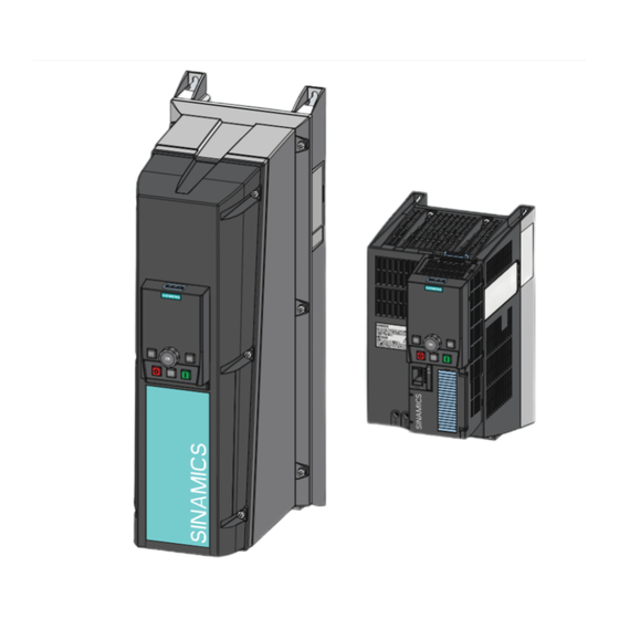
Design of the frequency converter Components and design of the frequency converter Power Module Control Unit SINAMICS G120 frequency converters comprise a (PM) and (CU). Figure 1-1 Design of the frequency converter (example) Frequency converters with Control Units CU230P-2; CU240B-2; CU240E-2 Getting Started, 01/2011, A5E02792536C AB... - Page 8 Design of the frequency converter Figure 1-2 Assembling components Components for commissioning The following tools are available to commission the frequency converter: ● Intelligent Operator Panel IOP ● Basic Operator Panel BOP-2 ● STARTER commissioning tool (PC software) Figure 1-3 Operator control options Frequency converters with Control Units CU230P-2;...
- Page 9 Design of the frequency converter Table 1- 1 Components and tools for commissioning and data backup Component or tool Order number Operator panel for BOP-2 - for snapping onto the frequency converter 6SL3255-0AA00-4CA1 commissioning, Copies drive parameters diagnostics and Two-line display ...
-
Page 10: Control Units
Design of the frequency converter 1.1 Control Units Control Units Different Control Unit versions The Control Units differ by the following main factors: ● Fieldbus interface type ● Type and scope of the functions – e.g. for CU230P-2… through additional specific technology functions for pumps, fans and compressors –... -
Page 11: Power Module
Design of the frequency converter 1.2 Power Module Power Module Power Modules are available in various degrees of protection with a different topology in the power range from between 0.37 kW up to 250 kW. The Power Modules are sub-divided into various frame sizes (FS). -
Page 12: Iop Intelligent Operator Panel
Design of the frequency converter 1.3 IOP Intelligent Operator Panel IOP Intelligent Operator Panel The IOP is an operator device with which you can commission the frequency converter locally, enter parameters and monitor operation. Selection menus and status displays are shown on the text and graphics display. - Page 13 Design of the frequency converter 1.3 IOP Intelligent Operator Panel Menu structure The menu structure shown here applies to the IOP with FW 1.1 and FW1.1HF. It provides an overview of where you can find application Wizards and additional setting functions. Instead of using the application Wizards, you can also use individual parameters to directly change all of the settings.
- Page 14 Design of the frequency converter 1.3 IOP Intelligent Operator Panel Frequency converters with Control Units CU230P-2; CU240B-2; CU240E-2 Getting Started, 01/2011, A5E02792536C AB...
-
Page 15: Installation
Installation Connecting the Power Module to the motor and power supply Figure 2-1 Connection diagrams for PM230, PM240, PM250 Note: The PM260 has an integrated line and sine-wave filter. Otherwise, the wiring of the PM260 corresponds to that of the PM250. Frequency converters with Control Units CU230P-2;... -
Page 16: Interfaces Of The Control Units
Installation 2.1 Interfaces of the Control Units Interfaces of the Control Units 2.1.1 Interfaces of the CU230P-2 31 31 +24V IN 32 32 GND IN 35 35 +10V OUT 36 36 50 50 51 51 52 52 53 53 10 10 AI 1+ 11 11 AI 1-... -
Page 17: Terminal Strips Of The Cu230P-2
Installation 2.1 Interfaces of the Control Units 2.1.2 Terminal strips of the CU230P-2 The wiring of the terminal strip is not shown completely, but as example for each terminal type. If you require more than six digital inputs, use terminals 3 and 4 (AI 0) or terminals 10 and 11 (AI 1) as additional digital inputs DI 11 or DI 12. -
Page 18: Interfaces Of The Cu240B-2 And Cu240E-2
Installation 2.1 Interfaces of the Control Units 2.1.3 Interfaces of the CU240B-2 and CU240E-2 31 31 +24V IN 32 32 GND IN 34 34 DI COM2 10 10 AI 1+ 11 11 AI 1- 26 26 AO 1+ 27 27 +10V OUT AI 0+ AI 0-... -
Page 19: Terminal Strips On Cu240B-2 Control Units
Installation 2.1 Interfaces of the Control Units 2.1.4 Terminal strips on CU240B-2 Control Units If you require more than four digital inputs, use terminals 3 and 4 (AI 0) as additional digital input DI 11. ① Wiring when using the internal power supplies. DI = high, if the switch is closed. -
Page 20: Terminal Strips On Cu240E-2 Control Units
Installation 2.1 Interfaces of the Control Units 2.1.5 Terminal strips on CU240E-2 Control Units The terminal strip wiring is not completely shown, only as example for each type of input and output. If you require more than six digital inputs, use terminals 3 and 4 (AI 0) or terminals 10 and 11 (AI 1) as additional digital inputs DI 11 or DI 12. -
Page 21: Selecting The Interface Assignment
Installation 2.2 Selecting the interface assignment Selecting the interface assignment The inverter offers different pre-defined settings for its interfaces. Choose the appropriate setting (macro) and wire the terminal strips according to the chosen setting. If none of the pre-defined settings suites your application completely, do the following steps: 1. - Page 22 Installation 2.2 Selecting the interface assignment Refer to the following Section on how you can obtain the GSD file: Getting the GSD file (Page 34). You must enable the safety function, see Section: Enable the fail-safe "Safe Torque Off" function (STO) (Page 29). Refer to the following Section on how you can obtain the GSD file: Getting the GSD file (Page 34).
- Page 23 Installation 2.2 Selecting the interface assignment Automatic / local - changeover between fieldbus and jog mode macro 7 – CU240B-2 Refer to the following Section on how you can obtain the GSD file: Getting the GSD file (Page 34). Automatic / local - changeover between fieldbus and jog mode macro 7 – CU230P-2 and CU240E-2 Refer to the following Section on how you can obtain the GSD file: Getting the GSD file (Page 34).
- Page 24 Installation 2.2 Selecting the interface assignment Motorized potentiometer – macro 9 – CU230P-2 and CU240E-2 Motorized potentiometer with safety function – macro 8 – CU240E-2, You must enable the safety function, see Section: Enable the fail-safe "Safe Torque Off" function (STO) (Page 29). Process industry –...
- Page 25 Installation 2.2 Selecting the interface assignment Two- or three-wire control – macros 12, 17, 18, 19, 20 – CU240B-2 Two- or three-wire control – macros 12, 17, 18, 19, 20 – CU230P-2 and CU240E-2 Frequency converters with Control Units CU230P-2; CU240B-2; CU240E-2 Getting Started, 01/2011, A5E02792536C AB...
- Page 26 Installation 2.2 Selecting the interface assignment Communication via USS – macro 21 – CU240B-2 Communication via USS – macro 21 – CU230P-2 HVAC and CU240E-2 Further information about the fieldbus USS can be found in the operating instructions. Communication via CAN – macro 22 – CU230P-2 CAN Further information about the CANopen fieldbus can be found in the operating instructions.
-
Page 27: Commissioning
(Page 12). If the IOP does not contain the actual frequency converter software, a message is displayed "Update is required". You can find the required data in the Internet under (http://support.automation.siemens.com/WW/view/en/43896115). In the basic commissioning select the control mode for the motor, enter the motor data and define the function of the frequency converter interfaces. -
Page 28: Settings In The Basic Commissioning Menu
Commissioning 3.1 Settings in the basic commissioning menu Settings in the basic commissioning menu Start the menu: WIZARD / BASIC COMMISSIONING The "Basic Commissioning" wizard guides you through commissioning in the following steps: Input screen of the IOP Selected setting on the IOP Parameter 01/21 Restore factory settings... -
Page 29: Enable The Fail-Safe "Safe Torque Off" Function (Sto)
Commissioning 3.2 Enable the fail-safe "Safe Torque Off" function (STO) Identifying motor data Alarm A07791 is output for as long as the frequency converter has still not identified the motor data. You must switch on the motor (e.g. from the IOP) to identify the motor data. The frequency converter switches-off the motor after the motor data identification has been completed. -
Page 30: The Most Important Parameters At A Glance
Commissioning 3.3 The most important parameters at a glance The most important parameters at a glance Table 3- 2 Defining the interfaces of the frequency converter Parameter Possible settings p0015 Macro drive unit Define the pre-assignment for the inputs and outputs using one of the macros 1 to 22 . Table 3- 3 Selecting the fieldbus protocol Parameter... - Page 31 Commissioning 3.3 The most important parameters at a glance Table 3- 6 Motor data according to the rating plate Parameter Possible settings p0100 Motor standard IEC / NEMA 0: Europe 50 [Hz] p0300 Motor type selection 0: No motor 1: Induction motor 2: Synchronous motor p0304 Motor voltage in [V]...
- Page 32 Commissioning 3.3 The most important parameters at a glance Table 3- 9 Digital outputs (relay outputs) Parameter Terminals Terminals Terminals Signal Important status signals CU240B-2 CU240E-2 CU230P-2 p0730 18 / 19 / 20 18 / 19 / 20 18 / 19 / 20 DO 0 r52.2 - operation enabled (motor running) r52.3 - fault active...
- Page 33 Commissioning 3.3 The most important parameters at a glance Table 3- 13 Analog outputs Parameter Terminals Terminals Terminals Signal Setting CU240B-2 CU240E-2 CU230P-2 p0771[0] 12 / 13 12 / 13 12 / 13 AO 0 Important status signals: p0771[1] 26 / 27 26 / 27 AO 1 0: Analog output locked...
-
Page 34: Data Backup On The Memory Card
GSD of your inverter: 1. You can find the SINAMICS inverter GSD on the Internet (http://support.automation.siemens.com/WW/view/en/22339653/133100). 2. The GSD is saved in the inverter. The inverter writes its GSD to the memory card if you insert the memory card in the inverter and set p0804 to 12. Using the memory card, you can then transfer the GSD to your PG/your PC. -
Page 35: Index
Index Series commissioning, 7 STARTER Analog input, 17, 19, 20 Download, 9 Analog output, 17, 19, 20 Order number, 9 Commissioning, 28 Temperature sensor, 17, 19, 20 Digital input, 17, 19, 20 Upload, 7 Digital output, 17, 19, 20 Download, 7 Drive ES Basic, 9 Frame size, 11 Frame sizes, 11... - Page 36 Siemens AG We reserve the right to make technical Industry Sector changes. Drive Technologies © Siemens AG 2011 Motion Control Systems Postfach 3180 91050 ERLANGEN GERMANY www.siemens.com/sinamics-g120...