Siemens SINAMICS S120 Operating Instructions Manual
Cabinet modules operator panel (option k08)
Hide thumbs
Also See for SINAMICS S120:
- Function manual (1094 pages) ,
- Diagnostic manual (947 pages) ,
- Manual (848 pages)
Table of Contents
Advertisement
Advertisement
Table of Contents

Related Manuals for Siemens SINAMICS S120


Summary of Contents for Siemens SINAMICS S120
- Page 3 ___________________ Cabinet Modules Operator Panel Preface AOP30 ___________________ Safety information ___________________ SINAMICS General ___________________ Commissioning S120 Cabinet Modules Operator Panel ___________________ Control via the operator AOP30 panel ___________________ Maintenance and servicing Operating Instructions Control version V4.7 04/2014 A5E03263551A...
- Page 4 Note the following: WARNING Siemens products may only be used for the applications described in the catalog and in the relevant technical documentation. If products and components from other manufacturers are used, these must be recommended or approved by Siemens. Proper transport, storage, installation, assembly, commissioning, operation and maintenance are required to ensure that the products operate safely and without any problems.
-
Page 5: Preface
This documentation is part of the manufacturer/service documentation for SINAMICS. All of the documents are available individually. Please contact your local Siemens office for further information about other available SINAMICS publications. For the sake of simplicity, this documentation does not contain comprehensive detailed information about all types of the product and cannot cover every conceivable case of installation, operation, or maintenance. - Page 6 Internet addresses Up-to-date information about our products can be found on the Internet at the following address: http://www.siemens.com Information about SINAMICS S120 Cabinet Modules can be found on the Internet at the following address: http://www.siemens.com/sinamics-s120-cabinet-modules Cabinet Modules Operator Panel AOP30...
-
Page 7: Table Of Contents
Table of contents Preface ..............................5 Safety information ........................... 9 General safety instructions ....................... 9 Handling electrostatic sensitive devices (ESD) ..............13 Industrial security ........................14 General ..............................15 Commissioning ............................. 17 Chapter content ........................17 First commissioning ........................ 18 Loading the firmware ...................... - Page 8 Table of contents Operation via the operator panel (LOCAL mode) ..............57 4.8.1 LOCAL/REMOTE key ......................58 4.8.2 ON key / OFF key ........................58 4.8.3 CCW / CW changeover ......................59 4.8.4 Jog ............................59 4.8.5 Increase setpoint / decrease setpoint ..................59 4.8.6 AOP setpoint ..........................
-
Page 9: Safety Information
Safety information General safety instructions DANGER Danger to life due to live parts and other energy sources Death or serious injury can result when live parts are touched. • Only work on electrical equipment if you are appropriately qualified. • Always observe the country-specific safety rules for all work. Generally, six steps apply when establishing safety: 1. - Page 10 Safety information 1.1 General safety instructions WARNING Danger to life when live parts are touched on damaged devices Improper handling of devices can cause damage. Hazardous voltages can be present at the housing or exposed components on damaged devices. • Ensure compliance with the limit values specified in the technical data during transport, storage and operation.
- Page 11 Safety information 1.1 General safety instructions WARNING Danger to life through unexpected movement of machines when using mobile wireless devices or mobile phones Using mobile radios or mobile phones with a transmit power > 1 W closer than approx. 2 m to the components may cause the devices to malfunction, influence the functional safety of machines therefore putting people at risk or causing material damage.
- Page 12 Safety information 1.1 General safety instructions NOTICE Device damage caused by incorrect voltage/insulation tests Incorrect voltage/insulation tests can damage the device. • Before carrying out a voltage/insulation test, disconnect the system/machine. All converters and motors are subject to a high voltage test in the manufacturer's facility. As a consequence, it is not necessary to carry out additional tasks in the system/machine.
-
Page 13: Handling Electrostatic Sensitive Devices (Esd)
Safety information 1.2 Handling electrostatic sensitive devices (ESD) Handling electrostatic sensitive devices (ESD) Electrostatic sensitive devices (ESD) are individual components, integrated circuits, modules or devices that may be damaged by either electric fields or electrostatic discharge. NOTICE Damage through electric fields or electrostatic discharge Electric fields or electrostatic discharge can cause malfunctions through damaged individual components, integrated circuits, modules or devices. -
Page 14: Industrial Security
Note Industrial security Siemens provides automation and drive products with industrial security functions that support the secure operation of plants or machines. They are an important component in a holistic industrial security concept. With this in mind, our products undergo continuous development. -
Page 15: General
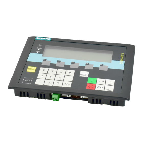
General Availability of option K08 Option K08 is available for the following S120 Cabinet Modules: ● Basic Line Modules ● Smart Line Modules ● Active Line Modules ● Booksize Cabinet Kits ● Motor Modules in chassis format Note Option K08 is only available in conjunction with the CU320-2 Control Unit (option K90/K95). Description Figure 2-1 AOP30 Advanced Operator Panel (option K08) - Page 16 General Characteristics ● Display with green backlighting (resolution: 240 x 64 pixels) ● 26-key keypad ● RS 232 interface ● Time and date memory powered by internal battery backup ● Four LEDs indicate the operating status of the drive unit: –...
-
Page 17: Commissioning
Commissioning Chapter content This chapter provides information on the following: ● First commissioning ● Loading the firmware ● First commissioning of the drive system (initialization) – Entering the infeed data (first commissioning: infeed) – Entering the motor data (drive commissioning) –... -
Page 18: First Commissioning
Commissioning 3.2 First commissioning First commissioning Start screen When the system is switched on for the first time, the Control Unit is initialized automatically. The following screen is displayed: Figure 3-1 Initial screen While the system is powering up, the parameter descriptions are loaded into the operator panel from the memory card. -
Page 19: Loading The Firmware
Commissioning 3.3 Loading the firmware Navigation within the interactive screens Within an interactive screen, the selection boxes can usually be selected using the <F2> and/or <F3> keys. Selection fields are generally texts surrounded by a frame. When they are selected, they are highlighted with a white text on a black background. The present value of a highlighted selection box can usually be changed by pressing <F5>... - Page 20 Commissioning 3.3 Loading the firmware Figure 3-4 Selection of firmware version (version on the memory card is older than the AOP version) You should answer this prompt with "YES" in order to match the functionality of the AOP30 to that of the firmware version on the memory card. The firmware will then be downloaded automatically to the operator panel.
-
Page 21: Initial Commissioning
Commissioning 3.4 Initial commissioning Initial commissioning 3.4.1 Entering the motor data When performing basic commissioning of the Motor Module, the motor data must be entered via the operator panel. This data can be taken from the type plate of the motor. Figure 3-6 Entering the motor data - type plate Table 3- 1... -
Page 22: First Commissioning: Infeed
First commissioning: infeed General Due to the modular design and the variety of applications for the SINAMICS S120 Cabinet Modules drive system, a variety of Line Modules may be used. Depending on the infeed used, some different parameters will have to be set during first commissioning. First commissioning of the various Line Modules (Basic Line Modules, Smart Line Modules and Active Line Modules) is described in the sections below. -
Page 23: Smart Line Module
Commissioning 3.4 Initial commissioning 3.4.2.2 Smart Line Module First commissioning: infeed Table 3- 3 Data input with infeed via a Smart Line Module • Input of the supply voltage in V. • Input of the source of the ON/OFF1 command. Navigate within the selection fields with <F2>... -
Page 24: Active Line Module
Commissioning 3.4 Initial commissioning 3.4.2.3 Active Line Module First commissioning: infeed Table 3- 4 Entering the infeed data • Input of the supply voltage in V • Selection of the Active Interface Modules, the default setting should not be changed. •... - Page 25 Commissioning 3.4 Initial commissioning Basic commissioning: Select oper. type Selecting the operation type for a drive. To navigate through the selection fields, choose <F2> or <F3>. To activate a selection, choose <F5>. Basic commissioning: Selecting the motor type and entering the motor data You can select the motor standard and type in the dialog screen.
- Page 26 Commissioning 3.4 Initial commissioning Note Selecting the motor type The selection of the motor type pre-assigns specific motor parameters and optimizes the operating characteristics and behavior. Details are described in the List Manual in the p0300 parameter. Note Selecting a listed motor (p0300 ≥ 100) When selecting a motor type ≥...
- Page 27 Commissioning 3.4 Initial commissioning Encoders for SMC20: 2001: 2048, 1 Vpp, A/B C/D R 2002: 2048, 1 Vpp, A/B R 2003: 256, 1 Vpp, A/B R 2004: 400, 1 Vpp, A/B R 2005: 512, 1 Vpp, A/B R 2006: 192, 1 Vpp, A/B R 2007: 480, 1 Vpp, A/B R 2008:...
- Page 28 Commissioning 3.4 Initial commissioning Note Pre-defined encoder type If a predefined encoder type is selected in p0400, then the settings of the following parameters p0404, p0405 and p0408 cannot be changed. If the connected encoder does not match any of the encoders predefined in p0400, follow the simple procedure below for entering the encoder data: •...
- Page 29 Commissioning 3.4 Initial commissioning Basic commissioning: Entering the basic parameters Entering the basic commissioning parame- ters To navigate through the selection fields, choose <F2> or <F3>. To activate a selection, choose <F5>. To change a parameter value, navigate to the required selection field and activate with <F5>.
- Page 30 Commissioning 3.4 Initial commissioning Note Enter the motor-side filter A filter on the motor side must be entered in p0230: • Option L07 – dv/dt filter compact plus Voltage Peak Limiter: p0230 = 2 • Option L08 – motor reactor: p0230 = 1 •...
- Page 31 Commissioning 3.4 Initial commissioning Basic commissioning: Motor identification Selecting motor identification • Navigate within the selection fields with <F2> and <F3>. • Activate your selection with <F5>. Stationary measurements increase control performance as deviations in the electrical characteristic values are minimized on ac- count of deviations in the material properties and manufacturing tolerances.
- Page 32 Commissioning 3.4 Initial commissioning WARNING Danger to life if the motor unexpectedly moves during motor identification in the rotating mode When selecting motor identification with optimization in the rotating mode, after commissioning, the drive initiates that the motor rotates with speeds that can reach the maximum motor speed.
-
Page 33: Parameter Reset To Factory Settings
Commissioning 3.5 Parameter reset to factory settings Parameter reset to factory settings The factory settings represent the defined original status of the device on delivery. Resetting the parameters to the factory settings means that all the parameter settings made since the system was delivered are reset. Resetting Parameters via AOP30 Set parameter filter to "Parameter reset": <MENU>... - Page 34 Commissioning 3.5 Parameter reset to factory settings Cabinet Modules Operator Panel AOP30 Operating Instructions, 04/2014, A5E03263551A...
-
Page 35: Control Via The Operator Panel
Control via the operator panel Chapter content This chapter provides information on the following: ● Image of the main menu ● Menu descriptions – Menu: Operation screen – Menu: Parameterization – Menu: Fault/alarm memory – Menu: Commissioning / service – Sprachauswahl/Language selection menu ●... -
Page 36: Operator Panel (Aop30) Overview And Menu Structure
Control via the operator panel 4.2 Operator panel (AOP30) overview and menu structure Operator panel (AOP30) overview and menu structure Description The display can be used for the following activities: ● Parameterization (commissioning) ● Monitoring status variables ● Controlling the drive ●... - Page 37 Control via the operator panel 4.2 Operator panel (AOP30) overview and menu structure Menu structure of the operator panel Figure 4-1 Menu structure of the operator panel Cabinet Modules Operator Panel AOP30 Operating Instructions, 04/2014, A5E03263551A...
-
Page 38: Menu: Operation Screen
Control via the operator panel 4.3 Menu: Operation screen Menu: Operation screen Description The operation screen displays the most important status variables for the drive unit: In its as-delivered condition, it displays the operating status of the drive, the direction of rotation, the time, as well as four drive variables (parameters) numerically and two in the form of a bar display for continuous monitoring. - Page 39 Control via the operator panel 4.3 Menu: Operation screen Selecting the "current drive" The AOP30 is used for operating devices that comprise more than one drive so that attention is focused on one drive (i.e. the "current drive"). The changeover is made in the main menu, the corresponding function key is labeled "Drive".
-
Page 40: Menu: Parameterization
The drive software is modular. The individual modules are called DOs ("drive objects"). Depending on the device configuration, the following DOs may be present more than once in a SINAMICS S120 Cabinet Modules system: General parameters for the Control Unit (CU320-2) •... - Page 41 Control via the operator panel 4.4 Menu: Parameterization Figure 4-5 Data set selection Explanation of the operation screen: ● "Max" shows the maximum number of data sets parameterized (and thereby available for selection) in the drive. ● "Drive" indicates which data set is currently active in the drive. ●...
-
Page 42: Menu: Fault/Alarm Memory
Control via the operator panel 4.5 Menu: Fault/alarm memory Menu: Fault/alarm memory When you select the menu, a screen appears containing an overview of faults and alarms that are present. For each drive object, the system indicates whether any faults or alarms are present. ("Fault" or "Alarm"... -
Page 43: Menu Commissioning / Service
Control via the operator panel 4.6 Menu commissioning / service Menu commissioning / service 4.6.1 Drive commissioning Selecting this option enables you to re-commission the drive from the main menu. ● If the operation screen of the "current drive" is focused on an infeed, you will go directly to the screen "First commissioning: infeed". -
Page 44: Drive Diagnostics
Control via the operator panel 4.6 Menu commissioning / service 4.6.3 Drive diagnostics Curve recorder The curve recorder provides a slow trace function, which monitors a signal trend. A signal selected via a parameter is shown in the form of a curve. Figure 4-6 Curve recorder The relevant settings of the curve recorder are changed via the F5 key or via the menu... -
Page 45: Aop Settings
Control via the operator panel 4.6 Menu commissioning / service ● Manual After selecting manual scaling and confirmation with "OK," a window opens in which the maximum and minimum limits for scaling can be set. Figure 4-7 Curve recorder - manual scaling After setting and applying the limits, you switch to the curve recorder and manual scaling is used. - Page 46 Control via the operator panel 4.6 Menu commissioning / service Display settings In this menu, you set the lighting, brightness, and contrast for the display. Define operation screen In this menu, you can switch between five operation screens. You can set the parameters that are to be displayed.
-
Page 47: Lists Of Signals For The Operation Screen
Control via the operator panel 4.6 Menu commissioning / service 4.6.4.1 Lists of signals for the operation screen The following tables list the factory default settings of the signals for the operation screen along with the associated reference variables and default settings for quick commissioning. Object B_INF Table 4- 1 List of signals for the operation screen - object B_INF... - Page 48 Control via the operator panel 4.6 Menu commissioning / service Object S_INF Table 4- 3 List of signals for the operation screen - object S_INF Signal Parameter Short name Unit Normalization (100%=...) see table below Factory setting (entry no.) DC-link voltage smoothed r0026 U_DC p2001...
- Page 49 Control via the operator panel 4.6 Menu commissioning / service Object A_INF Table 4- 5 List of signals for the operation screen - object A_INF Signal Parameter Short name Unit Normalization (100%=...) see table below Factory setting (entry no.) DC-link voltage smoothed r0026 U_DC p2001...
- Page 50 Control via the operator panel 4.6 Menu commissioning / service VECTOR object Table 4- 7 List of signals for the operation screen - VECTOR object Signal Parameter Short name Unit Normalization (100%=...) see table below Factory setting (entry no.) Speed setpoint upstream of ramp-function r1114 NSETP p2000...
- Page 51 Control via the operator panel 4.6 Menu commissioning / service Figure 4-13 Operation screen - example of a drive with vector control TM31 object Table 4- 9 List of signals for the operation screen – TM31 object Signal Parameter Short name Unit Normalization (100% = ...)
-
Page 52: Curve Recorder Settings
Control via the operator panel 4.6 Menu commissioning / service 4.6.4.2 Curve recorder settings In this menu, the following settings can be made: Parameter selection You can select the parameter whose signal is to be displayed in the form of a curve in the curve recorder. - Page 53 Control via the operator panel 4.6 Menu commissioning / service Synchronization settings can be made under "Additional settings": Synchronization (factory setting: None) ● None The times for the AOP and drive unit are not synchronized. ● AOP->Drive – If you activate this option, the AOP and drive unit are synchronized immediately whereby the current AOP time is transferred to the drive unit.
-
Page 54: Do Name, Display Mode
Control via the operator panel 4.6 Menu commissioning / service Daylight-saving time changeover (factory setting: No) ● No The time does not automatically change over to daylight-saving time. ● Yes Selection is only possible if synchronization is set to "None" or "AOP -> Drive". The time is then automatically set to summer or winter time. -
Page 55: Reset Aop Settings
Control via the operator panel 4.6 Menu commissioning / service 4.6.4.6 Reset AOP settings When you choose this menu option, the AOP factory settings for the following are restored: ● Language ● Display (brightness, contrast) ● Operation screen ● Control settings Note Restoring the factory setting When you reset parameters, all settings that are different to the factory settings are reset... - Page 56 Control via the operator panel 4.6 Menu commissioning / service Battery status This menu displays the battery voltage (in volts and as a bar chart). The battery ensures that the data in the database and the current time are retained. When the battery voltage is represented as a percentage, a battery voltage of ≤...
-
Page 57: Sprachauswahl/Language Selection Menu
Control via the operator panel 4.7 Sprachauswahl/Language selection menu Sprachauswahl/Language selection menu The operator panel downloads the texts for the different languages from the drive. You can change the language of the operator panel via the "Sprachauswahl/Language selection" menu. Note Additional languages for the display Languages in addition to the current available languages in the display are available on request. -
Page 58: Local/Remote Key
Control via the operator panel 4.8 Operation via the operator panel (LOCAL mode) 4.8.1 LOCAL/REMOTE key Activating the LOCAL mode: Press the LOCAL/REMOTE key LOCAL mode: LED lights up REMOTE mode: LED does not light up: the ON, OFF, JOG, direction reversal, faster, and slower keys are not active. -
Page 59: Ccw / Cw Changeover
Control via the operator panel 4.8 Operation via the operator panel (LOCAL mode) 4.8.3 CCW / CW changeover Settings: Menu – Commissioning/Service – AOP settings – Control settings Switching between CCW/CW (factory setting: No) ● Yes: Switching between CW/CCW rotation by means of the CW/CCW key possible in LOCAL mode ●... -
Page 60: Aop Setpoint
Control via the operator panel 4.8 Operation via the operator panel (LOCAL mode) Setpoint entry in LOCAL mode is unipolar. You can change the direction of rotation by pressing the key that allows you to switch between CW/CCW rotation. ● CW rotation and "Raise key" mean: The displayed setpoint is positive and the output frequency is increased. -
Page 61: Lock Aop Local Mode
Control via the operator panel 4.8 Operation via the operator panel (LOCAL mode) 4.8.7 Lock AOP LOCAL Mode Settings: Menu – Commissioning/Service – AOP settings – Control settings Inhibit AOP LOCAL mode (factory setting: No) ● Yes: Deactivates the "Control via operator panel" function, thereby disabling the LOCAL/REMOTE key. -
Page 62: Operator Input Inhibit / Parameterization Inhibit
Control via the operator panel 4.8 Operation via the operator panel (LOCAL mode) 4.8.11 Operator input inhibit / Parameterization inhibit To prevent users from accidentally actuating the control keys and changing parameters, you can activate an operator input / parameterization inhibit using a key-operated pushbutton. Two key icons appear in the top right of the display when these safety inhibits are enabled. -
Page 63: Saving The Parameters Permanently
Control via the operator panel 4.9 Saving the parameters permanently Access level (factory setting: Expert): The different parameters required for this complex application are filtered so that they can be displayed as clearly as possible. You select them according to the access level. An expert level, which must only be used by expert personnel, is required for certain actions. -
Page 64: Faults And Alarms
Control via the operator panel 4.11 Faults and alarms 4.11 Faults and alarms If a fault occurs, the drive displays the fault and/or alarm on the operator panel. Faults are indicated by the red "FAULT" LED and a fault screen is automatically displayed. You can use the F1 Help function to call up information about the cause of the fault and how to remedy it. - Page 65 Control via the operator panel 4.11 Faults and alarms You can call up an overview screen that displays the current status of faults and/or alarms for every drive object in the system by choosing MENU – Fault memory / alarm memory. A context menu featuring the "Back"...
- Page 66 Control via the operator panel 4.11 Faults and alarms Cabinet Modules Operator Panel AOP30 Operating Instructions, 04/2014, A5E03263551A...
-
Page 67: Maintenance And Servicing
Maintenance and servicing Replacing the backup battery Replacing the backup battery Figure 5-1 Replacing the backup battery Cabinet Modules Operator Panel AOP30 Operating Instructions, 04/2014, A5E03263551A... - Page 68 Maintenance and servicing 5.1 Replacing the backup battery 1. Disconnect the 24 V DC power-supply cable. 2. Disconnect the communication cable on the operator panel. 3. Open the cover of the battery compartment. 4. Remove the old battery. 5. Insert the new battery. 6.
-
Page 69: Loading The New Operator Panel Firmware From The Pc
Maintenance and servicing 5.2 Loading the new operator panel firmware from the PC Loading the new operator panel firmware from the PC Description Firmware might need to be loaded to the AOP if the AOP functionality has been updated. If, once the drive has powered up, the memory card is found to contain a different version of the firmware, a message appears on the AOP30 prompting you as to whether new firmware should be loaded. - Page 70 Maintenance and servicing 5.2 Loading the new operator panel firmware from the PC Cabinet Modules Operator Panel AOP30 Operating Instructions, 04/2014, A5E03263551A...
-
Page 71: Index
Index Acknowledge error from the AOP, 61 Jog, 59 Setpoint, 60 JOG, 59 Setpoint ramp-down time, 60 Setpoint ramp-up time, 60 Starting setpoint, 60 AOP30, 15 K08, 15 AOP30 Advanced Operator Panel, 15 LOCAL/REMOTE key, 58 Basic commissioning Lock AOP LOCAL Mode, 61 Enter the motor data, 25 Entering the basic parameters, 29 Entering the encoder data., 26... - Page 72 Index Set time, 52 Software Version, 55 Sprachauswahl/Language selection, 57 Structure, 37 OFF key, 58 ON key, 58 Operation screen, 38 Operator input inhibit / Parameterization inhibit key, 62 Operator panel Overview, 36 Parameter reset, 33 Resetting Parameters via AOP30, 33 Parameterization errors, 63 RS232, 15 RS232 serial interface, 15...