Table of Contents
Advertisement
Advertisement
Table of Contents

Related Manuals for Panasonic YF-0201Z5HGF


Summary of Contents for Panasonic YF-0201Z5HGF
- Page 1 Controller for resistance welder Operating Instructions YF-0201Z5 Model No. Before operating this product, please read the instructions carefully and save this manual for future use. First of all, please read “Safety precautions” or “Safety manual”. TSM80344...
- Page 2 Introduction ♦ Introduction This is the operating instructions for YF-0201Z5 series. First of all, please read and understand this operating instruction for proper and safe operation. ♦ Features • A wide selection of welding sequences and functions. (15 conditions, 2-step welding with 9-pulsation) •...
-
Page 3: Table Of Contents
♦ Table of Contents 1. Safety precautions ......4 5.1 Welding current adjustment ....22 5.2 Checking of set data ......22 2. Specifications ........5 6. Troubleshooting ......23 2.1 Rated specifications .........5 2.2 Appearance ..........5 7. Advanced functions ......25 2.3 Dimensions..........6 2.4 Performance ..........6 7.1 DIP switches (DPSW1, DPSW2) settings25... -
Page 4: Safety Precautions
Safety precautions Safety precautions WARNINGS Welding power source (5) Connect cables completely and insulate connection parts. Observe the following instructions to prevent the (6) Keep all cases, panels and covers securely in place. hazard. (7) Do not handle the welding power source with torn or wet gloves. -
Page 5: Specifications
Attention • If the set value and the maximum current value differ greatly, current won’t be supplied correctly. 2.1 Rated specifications Model number YF-0201Z5HGF 100 (±10%) Rated control power (Allowable range) 220/440 selectable (-20% to +10%) -
Page 6: Dimensions
Specifications 2.3 Dimensions Rubber vibration insulator Detecting input (to connect toroidal coil) 15 20 342.5 100VAC (Unit: mm) Fitting 2.4 Performance ( ) Current control range ( ) Compensation accuracy (an error to the full scale current value.) Lower limit of the constant current control range is 30% of •... -
Page 7: Installation
Installation 3.Installation 3.1 Installation site This product is designed for indoor use only. CAUTION Do not install it in any places subject to rain or water spray. ( ) Indoors, not subject to direct sunlight or rain, with less moisture and dust. (... -
Page 8: Connections
Installation 3.2 Connections Prior to connection work, turn off power to the line disconnect device and all WARNING input power. CAUTION Do not perform connection work with wet hands. Make sure that only qualified persons or persons who are familiar with welding machines take case of the Note connection work. -
Page 9: Basic Operation
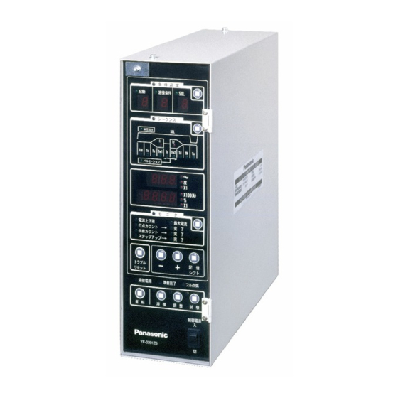
Basic operation 4.Basic operation 4.1 Names and functions 4.1.1 Operation panel 1) Lamps and indicators a.SCHEDULE lamp Lights when the schedule (job No. setting) mode is selected. b.START lamp Lights when the starting No. is selected in the schedule mode. c. - Page 10 Basic operation 2) Keys 1.SCHEDULE mode select key Enables to set welding conditions 2.SEQUENCE mode select key Enables to set sequence data 3.MONITOR mode select key Enables to set monitor data 4.“-” key Pressing this key decrements the number by the minimum unit.
-
Page 11: Rear Panel
Basic operation 4.1.2 Rear panel 1) External input/output terminals • Location and arrangement The external input/output terminals are located at the rear * See also the circuit diagram for connection work. side of the product. External I/O terminal External I/O terminals Start Start Start... - Page 12 Basic operation • External input terminals Name Description Switch means • • Short-circuit the termibals to to start welding oper- Start ation. • Start • With 4-schedule start mode: DIP switch: DPSW1-1 • welding condition corresponding to the start input. Start (To select a starting mode) •...
- Page 13 Basic operation • External output terminals Name Function Switch means • • An output that is turned on for 150 msec. (0.15 s) Hold end signal after the end of the hold time. • This signal does not output when the trouble output is on.
-
Page 14: Setting Welding Conditions
Basic operation 4.2 Setting welding conditions Welding conditions (see "10. Data sheet") can be set by turning on the CONTROL POWER (100VAC). However, to execute operation described in section “"4.3 Starting the welding operation" and "4.2.5 Adjustment and Test run", it is necessary to turn on both WELD POWER and CONTROL POWER. -
Page 15: Sequence Mode
Basic operation 4.2.2 Sequence mode Operation Lamp / indicator Indication Selecting the sequence setting mode ( ) •SEQUENCE lamp: • Press the SEQUENCE mode select key..•JOB lamp: •Job No. indicator: “1” Selecting the job No. ( ) Job No. indicator: Selected number •... - Page 16 Basic operation Operation Lamp / indicator Indication •“Tu” lamp: • Press ENTER/SHIFT key ......•“Tw1” lamp: •Data indicator A: Currently stored weld time 1 Note The up-slope time is not included in the weld time 1. Therefore, setting “1” or above as the up-slope time while the weld time is set at “0”...
- Page 17 Basic operation Operation Lamp / indicator Indication •“Td” lamp: • Press ENTER/SHIFT key....... •“TH” lamp: Remains ON •“ “ lamp: •Data indicator A: Currently stored hold time Note The down-slope time is not included in the hold time. Therefore, setting “1” or above as the down-slope time while the hold time is set at “0”...
-
Page 18: Schedule Mode
Basic operation 4.2.3 Schedule mode In case start mode is set to “4-schedule”, refer to the fol- Note lowing procedure to allocate a welding condition number For “15-schedule” start mode, it is not necessary to allo- to each start input. cate welding condition, as combination of the start inputs directly specify a welding condition. -
Page 19: Monitor Mode
Basic operation 4.2.4 Monitor mode Operation Lamp / indicator Indication Selecting the monitor mode ( ) •MONITOR lamp: • Press the MONITOR mode select key... •CUR.LIMIT lamp: •JOB lamp: •Job No. indicator: Currently stored job number. Selecting the job No. (... - Page 20 Basic operation Operation Lamp / indicator Indication Setting the production counter ( ) Data indicator B: Selected number • Select a number using “+” or “-” key....•PROD.CNTR. lamp: • Press ENTER/SHIFT key ......•”X1” (lower) lamp: <When the “Step-up” is selected> •STEP UP CNTR.
-
Page 21: Adjustment And Test Run
Basic operation 4.2.5 Adjustment and Test run ( ) Adjustment Adjustment • Press “ADJ.” key, then “CH1” DEG. is displayed on the “Data x100(A) indicator B”. • Pressure is being applied ↓ while the foot switch is kept Test run DEG. -
Page 22: Maintenance And Inspection
□ □ TSMP222 TSM222... -
Page 23: Troubleshooting
(*2) Treatment for the minor troubles includes 1) restart to reset and 2) Output of hold end signal. (*3) The “Memory writing error” does not affect the data, such as welding condition, WELD CNTR. PROD. CNTR and STEP UP CNTR. If the reset input does not cancel the error state, please contact Panasonic representatives. - Page 24 Troubleshooting • Setup errors Error type Contents [09-1] The up-slope time is set while the weld time 1 is set to “0” cycle. Up-slope error [09-2] The down-slope time is set while the weld time 2 is set to “0” cycle. Down-slope error [09-3] The pulsation time is set while the weld time 2 is set to “0”...
-
Page 25: Advanced Functions
Advanced functions 7.Advanced functions 7.1 DIP switches (DPSW1, DPSW2) settings • All the DIP switches are factory set to OFF side at shipment. DPSW2 • Prior to changing the DIP switch settings, turn off both control power and welding power. Changing the DIP DPSW1 switch settings while those powers are on doesn’t update the changes. -
Page 26: Functions
Advanced functions 7.2 Functions 7.2.1 Functions to be set by DPSW1 ( ) DPSW1-1: Starting mode ( ) DPSW1-3: Trouble mode This switch determines if the full wave detection is • 4-schedule mode: OFF treated in minor mode or major mode. (The other Inputting the starting input activates the troubles are treated in the major trouble mode.) -
Page 27: Functions To Be Set By Dpsw2
Advanced functions ( ) <Note> DPSW1-9: Current off selection In case of using this product to a single-phase AC • In case this switch is set to OFF, when the welding machine with the primary C.T., set the “Sequence stop/Current off” input terminals are “DPSW1-2”... -
Page 28: Step-Up
Advanced functions *If the counter value is changed after it reaches Note the preset value, the “COUNT UP” lamp is turned • Do not turn off the “CONTROL POWER” while “START” off. input is in ON state. (If such a thing occurs, turn ON the CONTROL POWER within 24 hours.) If such a thing •... -
Page 29: Signal-Up
Advanced functions 7.5 Signal-up It is a function to increase the welding current at the preset current incremental rate every time the “Step-up <Signal-up procedure> shift” input is given. This sequence is completed when the welding current Maximum current (I Max) reaches or exceeds the maximum current. -
Page 30: Selecting Functions
Advanced functions 7.6 Selecting functions Use JP1, JP2 or DPSW on the PC Board (TSMP222*) to select functions. ( ) JP1: short plug Set to select either “Normally open contact” or “Normally closed contact.” for trouble output Contact Normally open Normally closed DPSW2 type... -
Page 31: Sequence Chart
Advanced functions 4) Set the transformer winding ratio in the monitor mode. If the winging ratio is unknown and when installing the CT to a Panasonic welding machine, calculate the winding Machine type Formula ratio using the formula on the right and set it. -
Page 32: Timing Chart Of Accepting Starting Input32
Advanced functions 7.9 Timing chart of accepting starting input The starting input is checked for reconfirm one cycle (welding power frequency) after having received the first starting input. 1) 4-schedule mode (DPSW1-1: OFF) “Start 1” has priority over the others, therefore, the Start sequence is started with the start 1. -
Page 33: Circuit Diagram
Circuit diagram 8.Circuit diagram... -
Page 34: Parts List
Parts list 9.Parts list Name Part code Remarks TSMP222* Main control board PC Board TSMP451* Indication board PC Board TSMP450* Power board PC Board Transformer UTU21430 Control transformer Transformer UTU21421 Control transformer Switch DS850S00B Power switch Socket plug 12-3B Toroidal coil connecting connector Terminal TS212PLB8P TSMK0349... -
Page 35: Data Sheet
Data sheet 10.Data sheet 10.1 Data sheet 1 JOb No. Set item Symbol Unit Set range SOL output or SOL Pressure control 0.00 - 0.50 output Squeeze delay ycle 0 - 99 time Squeeze time ycle 3 - 99 Up-slope time ycle 0 - 20 Weld time 1... -
Page 36: Data Sheet 2
Data sheet 10.2 Data sheet 2 Set item Symbol Set range Data Maximum current 1 Max 50 - 500 (X100A) Monitor Welding transformer 10.0 - 99.9 turn ratio Set item Symbol Unit Set range Welding counter Counter 0 - 99 Production counter 0 - 9999 S0 welding count... - Page 38 Panasonic Welding Systems (Tangshan) Co., Ltd. Tangshan new & Hi-Tech Development Zone, 063020,Tangshan,Hebei, China TEL: 86-315-320-6075 86-315-320-6006 FAX: 86-315-320-6018 86-315-320-6070 URL: pwst.panasonic.cn 2009 Panasonic Welding Systems(Tangshan) Co.,Ltd. All rights reserved. Printed in China...