
Related Manuals for Siemens SIMATIC NET RUGGEDCOM M2100F


Summary of Contents for Siemens SIMATIC NET RUGGEDCOM M2100F
- Page 1 Installation Manual SIMATIC NET Rugged Ethernet Switches RUGGEDCOM M2100F Edition 04/2021 https://www.siemens.com...
- Page 2 Preface Introduction Installing the Device SIMATIC NET Device Management Rugged Ethernet Switches RUGGEDCOM M2100F Communication Ports Technical Specifications Installation Manual Certification 04/2021 C79000-G8976-1342-08...
- Page 3 Note the following: WARNING Siemens products may only be used for the applications described in the catalog and in the relevant technical documentation. If products and components from other manufacturers are used, these must be recommended or approved by Siemens. Proper transport, storage, installation, assembly, commissioning, operation and maintenance are required to ensure that the products operate safely and without any problems.
-
Page 4: Table Of Contents
Accessing Documentation ....................... v Registered Trademarks ......................v Warranty ..........................v Training ..........................vi Customer Support ........................vi Contacting Siemens ....................... vii Introduction ........................... 1 Feature Highlights ....................1 Description ......................1 Required Tools and Materials ................. 3 Decommissioning and Disposal ................3 Cabling Recommendations .................. - Page 5 Table of Contents Power Supply Specifications ................25 Failsafe Relay Specifications ................25 Supported Networking Standards ................ 25 Copper Ethernet Port Specifications ..............26 Fiber Optic Ethernet Port Specifications ............... 27 Operating Environment ..................28 Mechanical Specifications ..................28 Dimension Drawings ................... 28 Certification .........................
-
Page 6: Preface
Warranty Siemens warrants this product for a period of five (5) years from the date of purchase, conditional upon the return to factory for maintenance during the warranty term. This product contains no user-serviceable parts. Attempted service by unauthorized personnel shall render all warranties null and void. -
Page 7: Training
Siemens Sales representative. Customer Support Customer support is available 24 hours, 7 days a week for all Siemens customers. For technical support or general information, contact Siemens Customer Support through any of the following methods: Online Visit http://www.siemens.com/automation/support-request... -
Page 8: Contacting Siemens
Preface Contacting Siemens • Contact a local Siemens representative from Sales, Technical Support, Training, etc. • Ask questions or share knowledge with fellow Siemens customers and the support community Contacting Siemens Address Siemens AG Industry Sector 300 Applewood Crescent Concord, Ontario... - Page 9 Preface Contacting Siemens viii RUGGEDCOM M2100F Installation Manual, 04/2021, C79000-G8976-1342-08...
-
Page 10: Introduction
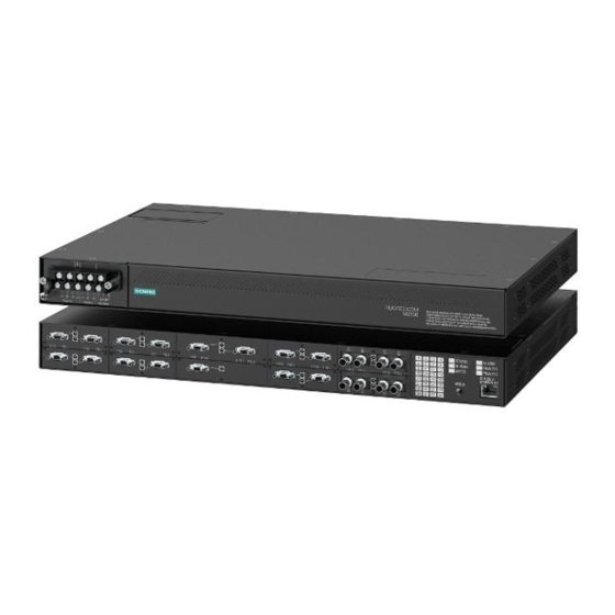
Introduction Feature Highlights Ethernet Ports • Up to 3 x Gigabit Ethernet ports (copper and fiber) • Up to 16 x 100Base-FX Fiber Fast Ethernet ports • 2-port modules for tremendous flexibility • Non-blocking, store and forward switching • Supports many types of fiber (multimode, single mode, bidirectional single strand) •... - Page 11 Introduction 1.2 Description Fiber or Copper Ethernet Ports Port Status Indicator LEDs Mode Button RS-232 Serial Console Port (RJ45) Display Mode Indicator LEDs Alarm Indicator LED Power Module Indicator LEDs Figure 1.1 RUGGEDCOM M2100F Communication Ports Ports for communicating with other devices or accessing the RUGGEDCOM M2100F operating system are described in "Communication Ports (Page 21)".
-
Page 12: Required Tools And Materials
Introduction 1.3 Required Tools and Materials about connecting to the device via the serial console port, refer to "Connecting to the Device (Page 19)". Required Tools and Materials The following tools and materials are required to install the RUGGEDCOM M2100F: Tools/Materials Purpose AC power cord (16 AWG) For connecting power to the device. -
Page 13: Gigabit Ethernet 1000Base-Tx Cabling Recommendations
Siemens also does not recommend using copper Ethernet ports to interface with devices in the field across distances that could produce high levels of ground potential rise (i.e. greater than 2500 V), during line-to-ground fault conditions. -
Page 14: Tamper-Evident Security Seals
NOTICE Worn, damaged or missing seals must be replaced immediately. Replacement seals are available for purchase from Siemens. For more information, contact a Siemens Sales representative. There are three ways to determine if a security seal has been tampered with: •... - Page 15 Introduction 1.6 Tamper-Evident Security Seals RUGGEDCOM M2100F Installation Manual, 04/2021, C79000-G8976-1342-08...
-
Page 16: Installing The Device
This product contains no user-serviceable parts. Attempted service by unauthorized personnel shall render all warranties null and void. Changes or modifications not expressly approved by Siemens AG could invalidate specifications, test results, and agency approvals, and void the user's authority to operate the equipment. -
Page 17: General Procedure
Visually inspect each item in the package for any physical damage. Verify all items are included. Note If any item is missing or damaged, contact Siemens for assistance. Mounting the Device The RUGGEDCOM M2100F is designed for maximum mounting and display flexibility. -
Page 18: Mounting The Device To A Rack
Installing the Device 2.3.1 Mounting the Device to a Rack Note For detailed dimensions of the device with either rack or panel hardware installed, refer to "Dimension Drawings (Page 28)". 2.3.1 Mounting the Device to a Rack The RUGGEDCOM M2100F can be secured to a standard 48 cm (19 in) rack using separately purchased rack mount adapters. -
Page 19: Mounting The Device To A Panel
Installing the Device 2.3.2 Mounting the Device to a Panel To secure the device to a standard 48 cm (19 in) rack, do the following: Note The device can be ordered with the communication ports located at the front or rear of the device. -
Page 20: Connecting The Failsafe Alarm Relay
Installing the Device 2.4 Connecting the Failsafe Alarm Relay To mount the device to a panel, do the following: Place the device against the panel and align the adapters with the mounting holes. Screw Panel Adapter Figure 2.2 Panel Mounting Install the supplied screws to secure the adapters to the panel. Connecting the Failsafe Alarm Relay The failsafe relay can be configured to latch based on alarm conditions. -
Page 21: Connecting Power
Installing the Device 2.5 Connecting Power Normally Open Common Normally Closed Figure 2.3 Failsafe Alarm Relay Wiring Connecting Power The RUGGEDCOM M2100F supports a single or dual redundant AC and/or DC power supplies. The RUGGEDCOM M2100F can be equipped with either a screw-type or pluggable terminal block, which provides power to both power supplies. -
Page 22: Connecting Ac Or Dc Power
Installing the Device 2.5.1 Connecting AC or DC Power • Equipment must be installed according to applicable local wiring codes and standards. 2.5.1 Connecting AC or DC Power To connect a single high AC, high DC or low DC power supply to the device, do the following: NOTICE Electrical hazard –... - Page 23 Installing the Device 2.5.1 Connecting AC or DC Power Connect the positive wire from the power source to the positive/live (+/L) terminal on the terminal block. Screw-Type Terminal Block Pluggable Terminal Block Jumper Positive/Live (+/L) Terminal Negative/Neutral (-/N) Terminal (-/N) Surge Ground Terminal Chassis Ground Terminal Chassis Ground Connection Figure 2.4...
-
Page 24: Wiring Examples
Installing the Device 2.5.2 Wiring Examples Using a #6 ring lug and #6-32 screw, secure the ground terminal on the power source to the chassis ground connection on the device. Make sure the lug is tightened to 1.7 N·m (15 lbf·in). Stainless Steel Stud #6-32 Screw #6 Ring Lug... - Page 25 Installing the Device 2.5.2 Wiring Examples Figure 2.6 Single AC Power Supply Figure 2.7 Single DC Power Supply RUGGEDCOM M2100F Installation Manual, 04/2021, C79000-G8976-1342-08...
- Page 26 Installing the Device 2.5.2 Wiring Examples Figure 2.8 Dual AC Power Supply Figure 2.9 Dual DC Power Supply RUGGEDCOM M2100F Installation Manual, 04/2021, C79000-G8976-1342-08...
- Page 27 Installing the Device 2.5.2 Wiring Examples Figure 2.10 Dual AC/DC Power Supply RUGGEDCOM M2100F Installation Manual, 04/2021, C79000-G8976-1342-08...
-
Page 28: Device Management
Device Management This section describes how to connect to and manage the device. Connecting to the Device The following describes the various methods for accessing the RUGGEDCOM M2100F console and Web interfaces on the device. For more detailed instructions, refer to the RUGGEDCOM ROS Configuration Manual for the RUGGEDCOM M2100F. -
Page 29: Configuring The Device
Device Management 3.2 Configuring the Device Name Description Comment RJ45 Male DB9 Female Ring Indicator The DSR, DCD and DTR pins are connected together internally. The CTS and RTS pins are connected together internally. RI is not connected. Communication Ports Connect any of the available Ethernet ports on the device to a management switch and access the RUGGEDCOM M2100F console and Web interfaces via the device's IP address. -
Page 30: Communication Ports
Communication Ports The RUGGEDCOM M2100F can be equipped with various types of communication ports to enhance its abilities and performance. Module Assignment Figure 4.1 Module Assignment Each type of module has a specific location in the RUGGEDCOM M2100F chassis: • Slot 5 supports a pair of Gigabit Ethernet (1 Gbps) ports •... -
Page 31: Copper Ethernet Ports
Communication Ports 4.1 Copper Ethernet Ports Port LED Figure 4.2 Port LEDs Copper Ethernet Ports The RUGGEDCOM M2100F supports several 10/100Base-TX and 10/100/1000Base- TX Ethernet ports that allow connection to standard Category 5 (CAT-5) unshielded twisted-pair (UTP) cables with Micro-D male connectors. The Micro-D connectors are directly connected to the chassis ground on the device and can accept CAT-5 shielded twisted-pair (STP) cables. -
Page 32: Fiber Optic Ethernet Ports
Communication Ports 4.2 Fiber Optic Ethernet Ports Fiber Optic Ethernet Ports Fiber optic Ethernet ports are available with either MTRJ (Mechanical Transfer Registered Jack), LC (Lucent Connector), SC (Standard or Subscriber Connector) or ST (Straight Tip) connectors. Make sure the Transmit (Tx) and Receive (Rx) connections of each port are properly connected and matched to establish a proper link. - Page 33 Communication Ports 4.2 Fiber Optic Ethernet Ports RUGGEDCOM M2100F Installation Manual, 04/2021, C79000-G8976-1342-08...
-
Page 34: Technical Specifications
Technical Specifications This section details the specifications and operating conditions of the device. Power Supply Specifications The RUGGEDCOM M2100F can be equipped with the following power supplies: NOTICE Electrical hazard – risk of damage to the device Make sure power input to the device is within the specified input range. Power Input Range Internal Fuse... -
Page 35: Copper Ethernet Port Specifications
Note • Maximum segment length is greatly dependent on factors such as fiber quality, and the number of patches and splices. Consult a Siemens sales associate when determining maximum segment distances. • All optical power numbers are listed as dBm averages. -
Page 36: Fiber Optic Ethernet Port Specifications
14.2 Typical. Typical distance. The maximum distance is greatly dependent on factors such as cable type, the number of connectors and number of splices. Consult a Siemens sales associates when determining maximum distances. Fast Ethernet (10/100 Mbps) Optical Specifications Mode... -
Page 37: Operating Environment
5.6 Operating Environment Typical distance. The maximum segment length is greatly dependent on factors such as fiber quality, and the number of patches and splices. Consult a Siemens sales associates when determining maximum segment distances. Operating Environment The RUGGEDCOM M2100F is rated to operate under the following environmental conditions. - Page 38 Technical Specifications 5.8 Dimension Drawings 438.15 Figure 5.1 Overall Dimensions RUGGEDCOM M2100F Installation Manual, 04/2021, C79000-G8976-1342-08...
- Page 39 Technical Specifications 5.8 Dimension Drawings 32.77 21.08 11.68 479.29 470.4 461.0 Figure 5.2 Rack Mount Dimensions RUGGEDCOM M2100F Installation Manual, 04/2021, C79000-G8976-1342-08...
- Page 40 Technical Specifications 5.8 Dimension Drawings 467.4 275.6 482.6 Figure 5.3 Panel Mount Dimensions RUGGEDCOM M2100F Installation Manual, 04/2021, C79000-G8976-1342-08...
- Page 41 Technical Specifications 5.8 Dimension Drawings RUGGEDCOM M2100F Installation Manual, 04/2021, C79000-G8976-1342-08...
-
Page 42: Certification
UL 62368-1 Information Technology Equipment – Safety Part 1: General Requirements 6.1.2 European Union (EU) This device is declared by Siemens AG to comply with essential requirements and other relevant provisions of the following EU directives: • EN 62368-1 Information Technology Equipment – Safety – Part 1: General Requirements •... -
Page 43: Fcc
Methods of Measurement The device is marked with a CE marking and can be used throughout the European community. A copy of the CE Declaration of Conformity is available from Siemens AG. For contact information, refer to "Contacting Siemens (Page vii)". -
Page 44: Iso
Quality management systems – Requirements 6.1.7 RoHS This device is declared by Siemens AG to meet the requirements of the following RoHS (Restriction of Hazardous Substances) directives for the restricted use of certain hazardous substances in electrical and electronic equipment: •... - Page 45 Certification 6.2 EMC and Environmental Type Tests EMC Type Tests per IEC 61850-3 Note • In the case of an all fiber port configuration, this product meets all Class 2 requirements. Otherwise, all Class 1 requirements are met for copper ports. •...
- Page 46 5 kV AC Power Ports Siemens-specified severity levels EMC Immunity Type Tests per IEEE 1613 Note The RUGGEDCOM M2100F meets Class 2 requirements for an all-fiber configuration and Class 1 requirements for copper ports. Class 1 allows for temporary communication loss, while Class 2 requires error-free and interrupted communications.
- Page 47 Certification 6.2 EMC and Environmental Type Tests Description Test Levels Dielectric Signal Ports 2 kV Strength DC Power Ports 2 kV AC Power Ports 2 kV Damped Enclosure Ports 100 A/m Oscillatory Magnetic Field Environmental Type Tests Test Description Test Levels IEC 60068-2-1 Cold Temperature Test Ad...
- Page 48 Further Information Siemens RUGGEDCOM https://www.siemens.com/ruggedcom Industry Online Support (service and support) https://support.industry.siemens.com Industry Mall https://mall.industry.siemens.com Siemens AG Digital Industry Process Automation Postfach 48 48 90026 NÜRNBERG GERMANY...