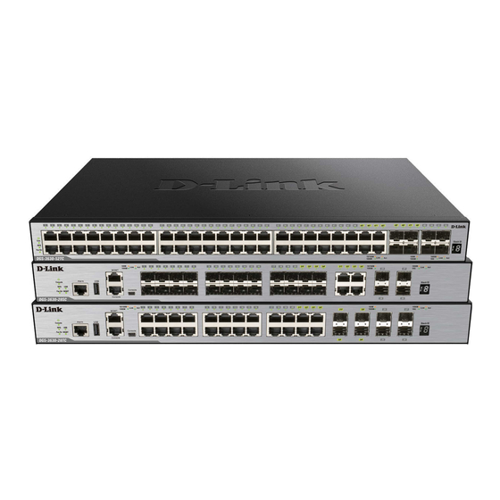
D-Link DGS-3630 Series Hardware Installation Manual
Layer 3 stackable managed switch
Hide thumbs
Also See for DGS-3630 Series:
- Reference manual (695 pages) ,
- User manual (9 pages) ,
- Hardware installation manual (61 pages)
Table of Contents
Advertisement
Quick Links
Advertisement
Table of Contents

Related Manuals for D-Link DGS-3630 Series


Summary of Contents for D-Link DGS-3630 Series
- Page 2 Information in this document is subject to change without notice. Reproduction in any manner whatsoever, without the written permission of D-Link Corporation, is strictly forbidden. Trademarks used in this text: D-Link and the D-LINK logo are trademarks of D-Link Corporation; Microsoft and Windows are registered trademarks of Microsoft Corporation.
-
Page 3: Typographical Conventions
DGS-3630 Series Layer 3 Stackable Managed Switch Hardware Installation Guide Intended Readers The DGS-3630 Series Layer 3 Stackable Managed Switch Hardware Installation Guide contains detailed information about the hardware specifications of the switches in this series. It also contains brief information on how to configure and manage a switch in this series. -
Page 4: Table Of Contents
DGS-3630 Series Layer 3 Stackable Managed Switch Hardware Installation Guide Table of Contents Intended Readers ................................ iii Typographical Conventions ............................iii Notes and Cautions ..............................iii 1. Introduction ................................6 Switch Description ............................... 6 Package Contents ................................ 6 Features ..................................7 2. - Page 5 DGS-3630 Series Layer 3 Stackable Managed Switch Hardware Installation Guide Switch to Another Switch ............................36 Switch Stacking ................................37 Switch to a Server ..............................40 5. Switch Management ............................... 41 Management Options ..............................41 Connecting to the Console Port ..........................41 Connecting to the RJ45 Console Port ........................
-
Page 6: Introduction
Features Switch Description The D-Link DGS-3630 Series is a high performance member of the D-Link Layer 3 switch family. Ranging from 10/100/1000 Mbps edge switches to core gigabit switches, the switch family has been future-proof designed to provide fault tolerance, flexibility, port density, robust security, and maximum throughput with a user-friendly management interface for the networking professional. -
Page 7: Features
One CD containing the Web UI Reference Guide, CLI Reference Guide, D-View module, and additional software. If any item is missing or damaged, please contact your local D-Link reseller for replacement. Features This switch is packed with an abundance of networking features that span inside and outside of the traditional Layer 3 framework. - Page 8 DGS-3630 Series Layer 3 Stackable Managed Switch Hardware Installation Guide Queue Handling: Strict Priority Queue (SPQ), 802.1ag Connectivity Fault Management Weighted Round Robin (WRR), and Weighted (CFM) Deficit Round Robin (WDRR) Y.1731 OAM Congestion Control: Weighted Random Early...
- Page 9 DGS-3630 Series Layer 3 Stackable Managed Switch Hardware Installation Guide MIB, 802.1p MIB, IF MIB, RADIUS Authentication Client MIB, RADIUS Accounting Client MIB, Ping & TRACEROUTE MIB, IPv6 MIB, ICMPv6 MIB, Entity MIB, VRRP MIB, RIPv2 MIB, OSPF MIB, IPv4 Multicast Routing...
-
Page 10: Hardware Components
DGS-3630 Series Layer 3 Stackable Managed Switch Hardware Installation Guide 2. Hardware Components This chapter describes the front, rear, and side panel components of all switches in the series. DGS-3630-28TC Switch DGS-3630-28SC Switch DGS-3630-28PC Switch DGS-3630-52TC Switch DGS-3630-52PC Switch DGS-3630-28TC Switch Front Panel Components The front panel of DGS-3630-28TC features a variety of LED indicators and ports. -
Page 11: Led Indicators
DGS-3630 Series Layer 3 Stackable Managed Switch Hardware Installation Guide LED Indicators Located on the front panel of this switch are LED indicators: Power, Console, RPS, Fan Err, USB, MGMT, Link/Act indicators for all the ports, and Stack ID. Figure 2-2 LED indicators for the DGS-3630-28TC... -
Page 12: Rear Panel Components
DGS-3630 Series Layer 3 Stackable Managed Switch Hardware Installation Guide Description Stack ID This 7-segment LED can display numbers from 1 to 9 and the following letters H, h, E, and G. The stacking ID (1 to 9) can be assigned manually by the user or automatically by the system. -
Page 13: Dgs-3630-28Sc Switch
DGS-3630 Series Layer 3 Stackable Managed Switch Hardware Installation Guide Figure 2-4 Side panels of the DGS-3630-28TC DGS-3630-28SC Switch Front Panel Components The front panel of DGS-3630-28SC features a variety of LED indicators and ports. Figure 2-5 Front panel view of the DGS-3630-28SC Ports that can be found on the front panel of this switch are listed in the table below. -
Page 14: Led Indicators
DGS-3630 Series Layer 3 Stackable Managed Switch Hardware Installation Guide For a complete list of SFP/SFP+ transceivers that are compatible with this switch, refer to the SFP Ports and SFP+ Ports sections in Appendix A - Technical Specifications. LED Indicators Located on the front panel of this switch are LED indicators: Power, Console, RPS, Fan Err, USB, MGMT, Link/Act indicators for all the ports, and Stack ID. -
Page 15: Rear Panel Components
DGS-3630 Series Layer 3 Stackable Managed Switch Hardware Installation Guide Description Stack ID This 7-segment LED can display numbers from 1 to 9 and the following letters H, h, E, and G. The stacking ID (1 to 9) can be assigned manually by the user or automatically by the system. -
Page 16: Dgs-3630-28Pc Switch
DGS-3630 Series Layer 3 Stackable Managed Switch Hardware Installation Guide Figure 2-8 Side panels of the DGS-3630-28SC DGS-3630-28PC Switch Front Panel Components The front panel of DGS-3630-28PC features a variety of LED indicators, ports and a Mode button. Figure 2-9 Front panel view of the DGS-3630-28PC Ports that can be found on the front panel of this switch are listed in the table below. -
Page 17: Led Indicators
DGS-3630 Series Layer 3 Stackable Managed Switch Hardware Installation Guide For a complete list of SFP/SFP+ transceivers that are compatible with this switch, refer to the SFP Ports and SFP+ Ports sections in Appendix A - Technical Specifications. LED Indicators Located on the front panel of this switch are LED indicators: Power, Console, RPS, Fan Err, USB, MGMT, Link/Act and PoE indicators for all the ports, Link/Act and PoE indicators for mode selection, and Stack ID. -
Page 18: Rear Panel Components
DGS-3630 Series Layer 3 Stackable Managed Switch Hardware Installation Guide Description This LED will light solid green when the corresponding ports are feeding power to the PoE devices plugged in. This LED will light solid amber when the port is in an error condition state. -
Page 19: Dgs-3630-52Tc Switch
DGS-3630 Series Layer 3 Stackable Managed Switch Hardware Installation Guide Figure 2-12 Side panels of the DGS-3630-28PC DGS-3630-52TC Switch Front Panel Components The front panel of DGS-3630-52TC features a variety of LED indicators and ports. Figure 2-13 Front panel view of the DGS-3630-52TC Ports that can be found on the front panel of this switch are listed in the table below. -
Page 20: Rear Panel Components
DGS-3630 Series Layer 3 Stackable Managed Switch Hardware Installation Guide Description Power This LED will light solid green after the Switch has been powered on successfully. This LED will be off when the Switch is no longer receiving power (i.e. powered off). -
Page 21: Led Indicators
DGS-3630 Series Layer 3 Stackable Managed Switch Hardware Installation Guide Components that can be found on the rear panel of this switch are listed in the table below. Component Description Security Lock Provide a Kensington-compatible security lock to be able to connect to a secure immovable device. -
Page 22: Side Panel Components
DGS-3630 Series Layer 3 Stackable Managed Switch Hardware Installation Guide Side Panel Components The side panels of this switch contain heat vents, fans, and rack-mounting screw holes. The heat vents are used to dissipate internal heat and facilitate internal air circulation. Do not block these openings. Leave at least 4 inches of space at the sides of the Switch for proper ventilation. - Page 23 DGS-3630 Series Layer 3 Stackable Managed Switch Hardware Installation Guide Figure 2-18 LED indicators for the DGS-3630-52PC Description Power This LED will light solid green after the Switch has been powered on successfully. This LED will be off when the Switch is no longer receiving power (i.e. powered off).
-
Page 24: Rear Panel Components
DGS-3630 Series Layer 3 Stackable Managed Switch Hardware Installation Guide Rear Panel Components The rear panel of this switch features an AC power connector, an outlet for an external redundant power supply, a USB port, LED indicators for USB and MGMT, an MGMT port, two console ports, an alarm port, a security lock, and a GND. -
Page 25: Side Panel Components
DGS-3630 Series Layer 3 Stackable Managed Switch Hardware Installation Guide Description This LED will blink when activity on this port is taking place. This LED will be off when there is no link present or when this interface was shut down from within the Switch’s configuration. -
Page 26: Installation
DGS-3630 Series Layer 3 Stackable Managed Switch Hardware Installation Guide 3. Installation Installation Guidelines Installing the Switch without a Rack Installing the Switch in a Standard 19" Rack Installing Transceivers into the Transceiver Ports Power On (AC Power) Installing the Redundant Power Supply (RPS) -
Page 27: Installing The Switch In A Standard 19" Rack
DGS-3630 Series Layer 3 Stackable Managed Switch Hardware Installation Guide Installing the Switch in a Standard 19" Rack This section is used to guide the user through installing the Switch into a switch rack. The Switch can be mounted in a standard 19"(1U) rack using the provided mounting brackets. -
Page 28: Power On (Ac Power)
DGS-3630 Series Layer 3 Stackable Managed Switch Hardware Installation Guide used to connect devices to the Switch over great distances. The maximum distance that the RJ45 wiring connection can reach is 100 meters. Fiber optic connections can span several kilometers. -
Page 29: Power Failure (Ac Power)
DGS-3630 Series Layer 3 Stackable Managed Switch Hardware Installation Guide Power Failure (AC Power) In the event of a power failure, just as a precaution, unplug the power cord from the Switch. After the power returns, plug the power cord back into the power socket of the Switch. - Page 30 DGS-3630 Series Layer 3 Stackable Managed Switch Hardware Installation Guide Figure 3-7 Slide the Retainer through the Tie Wrap 4. Circle the tie of the retainer around the power cord and into the locker of the retainer. Figure 3-8 Circle around the power cord...
-
Page 31: Installing The Redundant Power Supply (Rps)
Installing the Redundant Power Supply (RPS) The Redundant Power Supply (RPS) is designed to conform to the wattage requirements of D-Link’s Ethernet and Gigabit switches. It is an external RPS unit enclosed in solid metal case with sockets to connect AC or DC power sources on one end, and to connect to a switch’s internal power supply on the other end. -
Page 32: Installing The Rps Into A Rack-Mount Chassis
DGS-3630 Series Layer 3 Stackable Managed Switch Hardware Installation Guide Figure 3–10 Connecting a DGS-3630 Series Switch to the DPS-500A Remove the AC power cord from the AC power port of the Switch. Insert one end of the 14-pin DC power cable into the port on the switch and the other end into the RPS. - Page 33 DGS-3630 Series Layer 3 Stackable Managed Switch Hardware Installation Guide Figure 3-11 Front view of the DPS-700 1. Insert one end of the 22-pin DC power cable into the receptacle on the Switch and the other end into the Redundant Power Supply unit.
-
Page 34: Dps-800
DGS-3630 Series Layer 3 Stackable Managed Switch Hardware Installation Guide CAUTION: Do not connect the DPS-700 to the DGS-3630-28PC/52PC by using the 14-pin DC power cable. It may cause damage when using the wrong DC power cable. ONLY use the 22-pin DC power cable. - Page 35 DGS-3630 Series Layer 3 Stackable Managed Switch Hardware Installation Guide Figure 3–14 Install the DPS-800 in an Equipment Rack...
-
Page 36: Switch Connections
DGS-3630 Series Layer 3 Stackable Managed Switch Hardware Installation Guide 4. Switch Connections Switch to an End Node Switch to Another Switch Switch Stacking Switch to a Server Switch to an End Node An end node is a generic name for edge networking devices that will be connected to this switch. Typical examples of end nodes are Personal Computers (PCs), Notebooks, Access Points, Print Servers, VoIP Phones and more. -
Page 37: Switch Stacking
DGS-3630 Series Layer 3 Stackable Managed Switch Hardware Installation Guide Switch Stacking The DGS-3630 series supports stacking up to 9 switches together while being managed through one console connection on the master switch, or by an IP address through the MGMT port, or by multiple IP addresses through any of the RJ45/SFP/SFP+ ports using Telnet, the Web UI, and SNMP. - Page 38 DGS-3630 Series Layer 3 Stackable Managed Switch Hardware Installation Guide The figure below illustrates how switches can be stacked in a Duplex Chain formation using optical fiber cables connected to SFP+ transceivers or DAC with SFP+ connectors where the 2-port stacking configuration is used.
- Page 39 DGS-3630 Series Layer 3 Stackable Managed Switch Hardware Installation Guide The figure below illustrates how switches can be stacked in a Duplex Ring formation using optical fiber cables connected to SFP+ transceivers or DAC with SFP+ connectors where the 2-port stacking configuration is used.
-
Page 40: Switch To A Server
DGS-3630 Series Layer 3 Stackable Managed Switch Hardware Installation Guide Switch to a Server The Switch is ideal for connecting to a network backbone, server, or server farm. The RJ45 ports operate at a speed of 10/100/1000 Mbps. The SFP ports operate at a speed of 100/1000 Mbps.The SFP+ ports operate at a speed of 1/10 Gbps. -
Page 41: Switch Management
Switch. Most of the features available through the CLI can be accessed through the Web UI. Web browsers like Microsoft’s Internet Explorer, Mozilla Firefox, or Google Chrome can be used. For more detailed information about the Web UI, refer to the DGS-3630 Series Web UI Reference Guide. Connecting to the Console Port The front panel of the Switch provides an RJ45 and a mini-USB console port to connect a remote system for monitoring and configuring the Switch. - Page 42 DGS-3630 Series Layer 3 Stackable Managed Switch Hardware Installation Guide Connect the male DB9 connector on the console cable (shipped with the Switch) to the RS-232 serial port on the computer running terminal emulation software then insert the RJ45 connector into the RJ45 console port on the front of the Switch.
-
Page 43: Connecting To The Mini-Usb Console Port
DGS-3630 Series Layer 3 Stackable Managed Switch Hardware Installation Guide Connecting to the Mini-USB Console Port To use the mini-USB console port, the following equipment is needed: A terminal or a computer with a USB 2.0 port and the ability to emulate a terminal. - Page 44 DGS-3630 Series Layer 3 Stackable Managed Switch Hardware Installation Guide Figure 5-3 Device Manager Set the terminal emulation software as follows: Select the serial port that belongs to the virtual COM port. Set the data rate to 115200 baud.
-
Page 45: Connecting To The Switch For The First Time
DGS-3630 Series Layer 3 Stackable Managed Switch Hardware Installation Guide Boot Procedure V2.25.002 ------------------------------------------------------------------------------- Power On Self Test ........100 % MAC Address : F0-7D-68-30-36-00 H/W Version : A1 Please Wait, Loading 2.25.018 Runtime Image ....100 % UART init .......... -
Page 46: Creating A User Account
DGS-3630 Series Layer 3 Stackable Managed Switch Hardware Installation Guide Creating a User Account One of the first and most important tasks will be to create user accounts. Logging in using a predefined administrator- level username will give the user privileged access to the Switch's management software. Also this will prevent unauthorized access to the Switch and record the passwords for future reference. -
Page 47: Connecting To The Mgmt Port
DGS-3630 Series Layer 3 Stackable Managed Switch Hardware Installation Guide Connecting to the MGMT Port The front panel of the Switch features an Out-Of-Band (OOB) RJ45 MGMT port which can be used to connect to a computer using a standard Ethernet cable. A web browser or Telnet client can be used to connect to the Switch using the MGMT port. -
Page 48: Traps
DGS-3630 Series Layer 3 Stackable Managed Switch Hardware Installation Guide The Switch allows groups of users to be listed and configured with a shared set of privileges. The SNMP version may also be set for a listed group of SNMP managers. Thus, a group of SNMP managers can be created to view read-only information or receive traps using SNMPv1 while assigning a higher level of security to another group, granting read/write privileges using SNMPv3. -
Page 49: Web-Based Switch Configuration
DGS-3630 Series Layer 3 Stackable Managed Switch Hardware Installation Guide 6. Web-based Switch Configuration Introduction Logging into the Web UI Web User Interface (Web UI) Introduction Most software functions of the Switch can be managed, configured, and monitored via the embedded HTML Web UI. -
Page 50: Web User Interface (Web Ui)
Switch. This area displays the Switch’s ports and expansion modules. It also shows port activity based on a specific mode. Some management functions, including port monitoring, are accessible from here. Click the D-Link logo to go to the D-Link website. -
Page 51: Web Pages
DGS-3630 Series Layer 3 Stackable Managed Switch Hardware Installation Guide AREA 4 This area displays graphical, real-time monitoring gauges of Device Information, CPU Usage, and Memory Usage. Web Pages In area 2, mentioned above, the following main folders will be available for selecting. -
Page 52: Appendix A - Technical Specifications
DGS-3630 Series Layer 3 Stackable Managed Switch Hardware Installation Guide Appendix A - Technical Specifications General Feature Description Data Transfer Rates Full-duplex Ethernet 20 Mbps Fast Ethernet 200 Mbps Gigabit Ethernet 2 Gbps 10 Gigabit Ethernet 20 Gbps Physical Stacking... -
Page 53: Performance
DGS-3630 Series Layer 3 Stackable Managed Switch Hardware Installation Guide Feature Description Power Consumption DGS-3630-28TC: 42.4 Watts (Max.), 28.1 Watts (Standby) DGS-3630-28SC: 63.58 Watts (Max.), 30.1 Watts (Standby) DGS-3630-28PC: 44.3 Watts (Max., non-PoE), 469.3 Watts (Max., PoE), 34.6 Watts (Standby) DGS-3630-52TC: 62 Watts (Max.), 36 Watts (Standby) -
Page 54: Led Indicators
DGS-3630 Series Layer 3 Stackable Managed Switch Hardware Installation Guide Feature Description DGS-3630-28SC: 128 Gbps DGS-3630-28PC: 128 Gbps DGS-3630-52TC: 176 Gbps DGS-3630-52PC: 176 Gbps Maximum Packet Forwarding Rate DGS-3630-28TC: 95.24 Mpps DGS-3630-28SC: 95.24 Mpps DGS-3630-28PC: 95.24 Mpps DGS-3630-52TC: 130.95 Mpps DGS-3630-52PC: 130.95 Mpps... - Page 55 DGS-3630 Series Layer 3 Stackable Managed Switch Hardware Installation Guide Location Color Status Description Light on (G) Safeguard Engine in exhausted mode Port LED Mode An LED Mode Select Button to switch two modes in turn for all Indicator 10/100/1000Mbps ports on DGS-3630-28PC/52PC: ...
-
Page 56: Port Functions
DGS-3630 Series Layer 3 Stackable Managed Switch Hardware Installation Guide Port Functions Feature Description Console Port RJ45 or mini-USB interface for Out-Of-Band (OOB) CLI configuration RJ45 Ports Compliant with the following standards: IEEE 802.3 compliance IEEE 802.3u compliance ... - Page 57 DGS-3630 Series Layer 3 Stackable Managed Switch Hardware Installation Guide Feature Description DEM-302S-BXD (1000BASE-BX-D, single-mode, 2 km, TX: 1550 nm / RX: 1310 nm) DEM-302S-BXU (1000BASE-BX-U, single-mode, 2 km, TX: 1310 nm / RX: 1550 nm) DEM-330T (1000BASE-BX-D, single-mode, 10 km, TX: 1550 nm / RX: 1310 nm) ...
-
Page 58: Appendix B - Cables And Connectors
DGS-3630 Series Layer 3 Stackable Managed Switch Hardware Installation Guide Appendix B - Cables and Connectors Ethernet Cable When connecting the Switch to another switch, a bridge or hub, a straight-through Cat5/5e/6a/7 cable is necessary. Please review these products for matching cable pin assignment. -
Page 59: Console Cable (Rj45 To Rs-232)
DGS-3630 Series Layer 3 Stackable Managed Switch Hardware Installation Guide Console Cable (RJ45 to RS-232) A console cable is used to connect to the RJ45 console port of the Switch to access the command line interface. The following diagram and table show the standard RJ45 to RS-232 cable and pin assignments. -
Page 60: Console Cable (Usb To Mini-Usb)
DGS-3630 Series Layer 3 Stackable Managed Switch Hardware Installation Guide Console Cable (USB to Mini-USB) A console cable is used to connect to the USB console port of the Switch to access the command line interface. The following diagram and table show the standard USB (Type A) to mini-USB (Type B) cable and pin assignments. -
Page 61: Redundant Power Supply (Rps) Cable
DGS-3630 Series Layer 3 Stackable Managed Switch Hardware Installation Guide Redundant Power Supply (RPS) Cable When connecting the Switch to a Redundant Power Supply, an RPS cable is necessary. Please review these products for matching cable pin assignment. The following diagrams and tables show the standard RPS receptacle/connector and their pin assignments. - Page 62 DGS-3630 Series Layer 3 Stackable Managed Switch Hardware Installation Guide +12V +12V +12V +12V +12V +12V Power Present Power Good Power Present Power Good +12V +12V 22-pin DC power cable Figure Error! Use the Home tab to apply AppendixHeading to the text that you want to appear here.-2 Redundant Power Supply...
- Page 63 DGS-3630 Series Layer 3 Stackable Managed Switch Hardware Installation Guide +12Ven +12Ven LS-54V LS-54V -54V -54V -54Vrtn -54Vrtn NC/GND RPS Present Status_2 Status_1 RPS PG Status_2 RPS Present RPS PG Status_1 +12VRTNsen +12VRTNsen LS+12V LS+12V -54Vsen -54Vsen -54VRTNsen -54VRTNsen...
-
Page 64: Alarm Connector (Rj45)
DGS-3630 Series Layer 3 Stackable Managed Switch Hardware Installation Guide Alarm Connector (RJ45) External devices can be connected to the alarm port to either trigger an alarm event or to be the recipient of an alarm event triggered by the Switch. External device connections can be paired together and connected to the alarm port using a standard RJ45 connector. -
Page 65: Safety/Sécurité
DGS-3630 Series Layer 3 Stackable Managed Switch Hardware Installation Guide Safety/Sé curité Safety Instructions General Precautions for Rack-Mountable Products Protecting Against Electrostatic Discharge Safety Instructions Please pay careful attention to the following safety guidelines to ensure your own personal safety and to help protect your system from potential damage. -
Page 66: Consignes De Sécurité
DGS-3630 Series Layer 3 Stackable Managed Switch Hardware Installation Guide To help protect the system from sudden, transient increases and decreases in electrical power, use a surge suppressor, line conditioner, or uninterruptible power supply (UPS). Position system cables and power cables carefully. Route cables so that they cannot be stepped on or tripped over. -
Page 67: General Precautions For Rack-Mountable Products
DGS-3630 Series Layer 3 Stackable Managed Switch Hardware Installation Guide Danger électrique: Seul le personnel qualifié doit effectuer les procédures d'installation. Avant de procéder à l'entretien, débranchez tous les cordons d'alimentation pour mettre le périphérique hors tension. ... -
Page 68: Protecting Against Electrostatic Discharge
DGS-3630 Series Layer 3 Stackable Managed Switch Hardware Installation Guide CAUTION: Installing systems in a rack without the front and side stabilizers installed could cause the rack to tip over, potentially resulting in bodily injury under certain circumstances. Therefore, always install the stabilizers before installing components in the rack. - Page 69 DGS-3630 Series Layer 3 Stackable Managed Switch Hardware Installation Guide Handle all sensitive components in a static-safe area. If possible, use antistatic floor pads, workbench pads and an antistatic grounding strap.
-
Page 70: Warranty
DGS-3630 Series Layer 3 Stackable Managed Switch Hardware Installation Guide Warranty... -
Page 71: Technical Support
DGS-3630 Series Layer 3 Stackable Managed Switch Hardware Installation Guide Technical Support...