
Related Manuals for Siemens DPU


Summary of Contents for Siemens DPU
- Page 1 User’s Manual DEVICE PROGRAMMING UNIT (DPU) Siemens Industry, Inc. Building Technologies Division P/N 315-033260-9...
-
Page 3: Table Of Contents
Table of Contents Introduction ................General Description and Features ............3 Getting Started ..................5 Printer Setup ..................6 Adjusting the LCD and Backlighting ........... 8 Programming ................ FireFinder-XLS, FS-250 and FC20 (FC2025, FC2050, FC2005, FC922, FC924 and FC901) Detectors and Devices .......... 9 MXL Detectors and Devices ............... - Page 4 CONTENTS DEVICE PROGRAMMING UNIT USER’S MANUAL Table of Contents (cont.) Maintenance ............... Updating the Firmware ..............43 Charging the Internal Batteries ............45 Replacing the Batteries ..............45 Troubleshooting .................. 46 ©2011 Copyright Siemens Industry, Inc. TABLE OF CONTENTS...
-
Page 5: Introduction
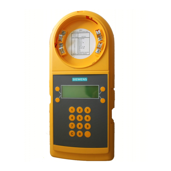
A DB-11 base is integrated into the body of the DPU for programming intelligent detectors. An external adaptor must be used for programming detectors that require a DB-3S base. - Page 6 DEVICE PROGRAMMING UNIT USER’S MANUAL DB-11 DETECTOR 4 X 20 BASE DISPLAY KEYPAD POWER SWITCH EXTERNAL POWER/ BATTERY CHARGING CONNECTOR TOP OF DPU CABLE COMPARTMENT RED AND BLACK GREEN BANANA JACKS BANANA JACK FOR DEVICES FOR GROUND (TRIs, MSIs) FAULT CABLE...
-
Page 7: General Description And Features
CHAPTER 1 | DEVICE PROGRAMMING UNIT USER’S MANUAL When the optional label printer is used, the DPU may be configured to print multiple labels for each address. This can be done as each of the devices is programmed or in a batch printing mode. - Page 8 Batteries and Battery Selection Switch The DPU battery compartment is located on the bottom rear of the DPU. It will accept either six Alkaline AA or six Nickel Metal Hydride (NiMH) AA batteries. Charging Alkaline batteries may damage the DPU and could cause personal injury.
-
Page 9: Getting Started
AA batteries are inserted correctly in the battery compartment. • If the DPU is to be operated from AC, connect the external power supply to the connector provided on the DPU and then connect it to the wall outlet. -
Page 10: Printer Setup
Printer Setup If the optional label printer is to be used to print labels, it must first be set up in the DPU. To do this, press SETUP then PRINTER from the Main Menu. This will bring up the PRINTER SETUP screen. - Page 11 CHAPTER 1 | DEVICE PROGRAMMING UNIT USER’S MANUAL PRINTER SETUP <SETTINGS BULK> <EXIT COPIES> • Press SETTINGS to select the printer. Two printer choices are available: PT-9200DX and PT-9500PC. (The model number is located on either the bottom or back of the printer.) To toggle the selection between the two choices, press CHANGE.
-
Page 12: Adjusting The Lcd And Backlighting
When the settings are satisfactory, press the “C” key on the keypad and the DPU display will return to the Main Menu. The DPU is now set up and ready for use. For instruc- tions on specific operations, refer to the pertinent section of the manual. -
Page 13: Programming
FC901) Detectors and Devices In FireFinder-XLS, FS-250 and FC20 (FC2025, FC2050, FC2005, FC922, FC924 and FC901) systems, the DPU is used only to set the address of detectors or devices. The other configuration data such as ASD settings, usage, and the type of the inputs on HTRIs, are sent from the applicable panel’s programming tool. - Page 14 DEVICE PROGRAMMING UNIT USER’S MANUAL FD-UL SERIES To Program/Test A Compatible FDUL Series Detector: DETECTOR • Align the knobs to base portion of the DPU and insert detector into base. • Rotate the detector clockwise until it stops and locks in place.
- Page 15 HTRI/TRI device. the black banana jack. To Program/Test A Compatible Series ILI/ILP PROGRAMMING Detector, connect the DPU to the DB-3S Base PLUG Adaptor: LOCATING • Insert programming plug of P/N 515-033925 into the red and black banana jacks in the cable compartment in the bottom of the DPU.
- Page 16 FireFinder-XLS, FS-250, FC2025, FC2050, FC922 and FC924 are limited to 252; for FC2005 and FC901 they are limited to 50. The loop number will only appear if the DPU has been configured for label printing. • Press ADDRESS. The cursor will appear under the...
-
Page 17: Mxl Detectors And Devices
Press RE-DO to return to the top level of the programming display. Press EXIT to escape from programming and return to the Main Menu. When the device is removed, the DPU will return to the first programming screen. When programming or testing HTRI-S/-D/-R/-M,... - Page 18 CHAPTER 2 DEVICE PROGRAMMING UNIT USER’S MANUAL • To adjust the LOOP and ADDRESS settings, press SETTINGS. The DPU will display a screen similar to the following: FP-11 LOOP=012 ADDRESS=41 <LOOP ADDRESS> <EXIT PROGRAM> Press the LOOP or ADDRESS button to move the cursor over the loop or address number, and then use the keypad to set the appropriate number.
-
Page 19: Tri-S, Tri-R, And Tri-M
PROGRAM button. The DPU will prompt the user to insert or connect a device or detector. The DPU is not equipped with polarity reversal for TRI devices, and MS manual stations. If the display searches for a device for longer than two seconds, reverse the polarity of the programming cable. - Page 20 Press the LOOP or ADDRESS button to move the cursor over the loop or address number, then use the keypad to set the number. The loop number will appear only if the DPU has been configured for label printing. Press EXIT to return to the previous Menu.
-
Page 21: Tri-Dual (Tri-D)
TRIs must be programmed using cable P/N 555-133891 that is stored in the cable compartment in the bottom of the DPU. Before starting to program TRIs, open the cable compartment and insert the programming plug in one end of the cable into the red and black banana jacks in the cable compartment of the unit. - Page 22 Press the LOOP or ADDRESS button to move the cursor over the loop or address number, then use the keypad to set the number. The loop number will appear only if the DPU has been configured for label printing. Press EXIT to return to the previous Menu.
- Page 23 CHAPTER 2 | DEVICE PROGRAMMING UNIT USER’S MANUAL This screen allows the usage and the contact state of the first input (#1) to be changed. Press the TROUBLE button to change the usage setting. As the button is pressed, the usage in the top line changes and the label on the button sequences between ALARM, TROUBLE, and STATUS.
-
Page 24: Changing A Device Id
OK?> Press the ID-60P/PT button to cycle through the possible IDs that may be set. The DPU will only present IDs that the device will accept. When the ID is set correctly, press OK to return to the programming mode to finish programming the device or press EXIT to return to the programming mode without changing the ID. -
Page 25: Fs-100 Detectors And Devices
DEVICE PROGRAMMING UNIT USER’S MANUAL FS-100 Detectors and Devices Usage and configuration information for FS-100 devices and detectors may only be programmed by the panel or configuration tool. The DPU is only capable of setting the address of these devices. Smoke Detectors •... - Page 26 CHAPTER 2 DEVICE PROGRAMMING UNIT USER’S MANUAL The loop number will only appear if the DPU has been configured for label printing. • If the loop and address information is correct, press PROGRAM. The DPU will indicate that it is program-...
-
Page 27: Fs-Tri-S, Fs-Tri-R, Fs-Tri-M, Fs-Ms And Fs-Czm
These devices must be programmed using cable P/N 555-133891 that is stored in the cable compartment in the bottom of the DPU. Before starting to program FS-TRIs, FS-MSs or FS-CZMs, open the cable compart- ment and insert the programming plug in one end of the cable into the red and black banana jacks in the cable compartment of the unit. -
Page 28: Fs-Tri-D
FS-TRIs must be programmed using cable P/N 555- 133891 that is stored in the cable compartment in the bottom of the DPU. Before starting to program FS-TRIs, open the cable compartment and insert the program- ming plug in one end of the cable into the red and black banana jacks in the cable compartment of the unit. - Page 29 DEVICE PROGRAMMING UNIT USER’S MANUAL • Connect the device programming cable to the device to be programmed. (Refer to Figure 2, pages 10-11.) When the DPU has detected the device, the display will appear similar to the following: FS-TRI-D AL/AL NO/NO ADDRESS=41 ADDRESS>...
- Page 30 CHAPTER 2 DEVICE PROGRAMMING UNIT USER’S MANUAL This page has been left intentionally blank. PROGRAMMING...
-
Page 31: Testing
Testing a FireFinder-XLS / FS-250 / FC20 (FC2025, FC2050, FC2005, FC922, FC924 or FC901) Loop The DPU may be used to test FireFinder-XLS / FS-250 / FC20 (FC2025, FC2050, FC2005, FC922, FC924, FC901) loops before the system is connected. The DPU checks that all of the devices are communicating and also checks for ground faults and short circuits. - Page 32 • Insert the programming plug in one end of Cable P/N 555-133891 into the red and black jacks in the cable compartment in the bottom of the DPU. • Attach the two alligator clip adaptors provided to the programming plug on the other of cable P/N 555-133891.
- Page 33 The top line indicates if there are any ground faults on the loop. The second line indicates how many devices the DPU has detected on the loop. It may take more than a minute to detect all of the devices on the loop.
- Page 34 CHAPTER 3 DEVICE PROGRAMMING UNIT USER’S MANUAL — c t i t i n c t i t i n c t i t i n c t i t i n l l a e l i i n i l l u l l u t n i...
-
Page 35: Testing A Device Or Detector
The DPU prompts the user to insert or connect a device. (Refer to Figure 2, pages 10-11, to install devices for testing.) When the device is detected, the test is run. The DPU will display the type of device tested and the address, as shown below: TESTING SUCCESSFUL... -
Page 36: Firefinder-Xls / Fs-250 / Fc20 (Fc2025, Fc2050, Fc2005, Fc922, Fc924, Fc901)
FC901) At the Main Menu press TEST then press MANUAL. The DPU will prompt for a device to be connected or a detector to be inserted. (Refer to Figure 2, pages 10-11, to install devices for testing.) When the device or... - Page 37 CHAPTER 3 | DEVICE PROGRAMMING UNIT USER’S MANUAL Table 3 describes the diagnostic data displayed in the preceding screens. This data is applicable to all H-Series devices and to all FD-UL Series devices except FDOOTC441/OOHC941 and FDCIO422. The diagnostic data for the FDOOTC441/OOHC941 is described in Table 4 and the diagnostic data for the FDCIO422 is described in Table 5.
-
Page 38: Fdootc441/Oohc941 Manual Test
CHAPTER 3 DEVICE PROGRAMMING UNIT USER’S MANUAL FC20 (FC2025, FC2050, FC2005, FC922, FC924, FC901) MANUAL TEST FOR FDOOTC441/OOHC941 Manual testing of the FDOOTC441/OOHC941 will retrieve and display diagnostic information in a series of four screens instead of the three-screen display for all of the other devices. - Page 39 CHAPTER 3 | DEVICE PROGRAMMING UNIT USER’S MANUAL l a i g i l v i t y t i . ) t - i t l t i r , a i , l a l l i , l a o i l .
-
Page 40: Fdcio422 Manual Test
CHAPTER 3 DEVICE PROGRAMMING UNIT USER’S MANUAL FC20 (FC2025, FC2050, FC2005, FC922, FC924, FC901) MANUAL TEST FOR FDCIO422 Manual testing of the FDCIO422 will retrieve and display diagnostic information in a series of three screens. The FDCIO422 three-screen display differs from the displays of the other devices because the FDCIO422 can have four usage settings. -
Page 41: Mxl / Fs-100 Manual Test
CHAPTER 3 | DEVICE PROGRAMMING UNIT USER’S MANUAL l a i c t i , l a v i t c t i , l a v i t c t i d i l , l a v i t c t i d i l , l a... - Page 42 CHAPTER 3 DEVICE PROGRAMMING UNIT USER’S MANUAL MXL / FS-100 Manual testing of the MXL / FS-100 detectors and devices will retrieve and display diagnostic information in a number of screens. The NEXT button may be used to page to the next screen of information. Table 6 shows the information that is displayed.
-
Page 43: Printing Labels
The printer must be set up in the DPU before labels can be printed. Refer to Printer Setup on page 6. PRINTING LABELS... -
Page 44: Automatic Printing
Press EXIT three times to return to the Main Menu display. If the printer does not work, turn off the DPU, wait a few seconds, and then turn it back on and try again. Bulk Printing From one to nine copies of each label may be printed for a range of addresses by using the bulk print facility. - Page 45 To return to the bulk printing screen to print another batch of labels, use the EXIT button. If the printer does not work, turn off the DPU, wait a few seconds, and then turn it back on and try again.
- Page 46 CHAPTER 4 DEVICE PROGRAMMING UNIT USER’S MANUAL This page has been left intentionally blank. PRINTING LABELS...
-
Page 47: Maintenance
Maintenance Updating the Firmware The firmware in the DPU may be updated in the field without disassembly of the unit by connecting a PC to the RJ11 printer/update port and downloading the software to it. Some settings may change during firmware update. Be sure to note these settings before performing the update and check them afterwards. - Page 48 Press OK on the DPU. The DPU is now ready to accept the upload. To ensure the DPU is communicating with the PC at this point, click the toolbar button with the binoculars. If a “Timeout Waiting for Configuration reply” message is displayed, the DPU is not communicating properly.
-
Page 49: Charging The Internal Batteries
Attempting to recharge non-rechargeable batteries is dangerous and could result in damage to the DPU or possible explosion. Follow these step to recharge the internal batteries: Check that rechargeable (NiMH) batteries have been installed and that the selection switch inside the battery compartment is set for rechargeables (NiMH). -
Page 50: Troubleshooting
1. Press any key (the unit may be in low power mode) 2. Check the batteries 3. Check the power • If the printer does not seem to work, turn off the DPU, wait a few seconds, and then turn it back on and try again. MAINTENANCE... - Page 52 P/N 315-033260-9 Siemens Industry, Inc. Siemens Canada Limited Building Technologies Division Building Technologies Division Florham Park, NJ 07932 2 Kenview Boulevard Brampton, Ontario L6T 5E4 Canada...