Table of Contents
Advertisement
Quick Links
Advertisement
Table of Contents

Related Manuals for Siemens FPI-32


Summary of Contents for Siemens FPI-32
- Page 1 MODEL FPI-32 PROGRAMMER/TESTER Operations Manual Siemens Industry, Inc. Siemens Building Technologies, Ltd. Building Technologies Division Fire Safety & Security Products Florham Park, NJ 2 Kenview Boulevard Brampton, Ontario P/N 315-090077-10 L6T 5E4 Canada firealarmresources.com...
- Page 2 Due to the implementation of the advanced searching algo- rithm, devices connected to the TRI/MSI input jack of the FPI-32 must be connected with the correct polarity. If a de- vice is not found by the programmer/tester, simply reverse the input leads and the device should be found within three seconds.
-
Page 3: Table Of Contents
Selecting Normally Open (NO) or Normally Closed (NC) for TRI Devices Verifying Device Information for TRI Devices Backward Compatibility Mode Changing the Device ID Establishing an Address Completing the Programming TEST MODE Entering the Test Mode Device Passed Device Failed MENU MODE FPI-32 Menu Mode firealarmresources.com... - Page 4 TRI/MSI, etc., connected with the proper polarity. When one of these devices is connected improperly, the searching algorithm will not find the device. In this case, the display on the FPI-32 reminds the user to try swapping the connect wire to find the device.
-
Page 5: Operation
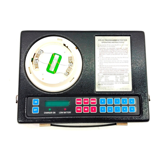
OPERATION OPERATION The Model FPI-32 Programmer/Tester is used in the field to program or test any ID-60 Series detectors, IL Series detectors, FP Series detec- tors, MSI Series manual stations, or TRI modules. Refer to Figure 1 below for identification of the parts of the FPI-32. - Page 6 OPERATION CONNECTING THE PROGRAMMER/TESTER The FPI-32 comes provided with a wall transformer with one end that plugs into any standard AC power outlet and a cable at the other end that connects to the back of the Programmer/Tester unit, where marked AC/ BATTERY RECHARGE.
-
Page 7: Modes Of Operation
To connect a TRI or MSI device to the Programmer/Tester, use the cable provided and connect one end to the module and the other to the rear of the FPI-32 where marked TRI/MSI. Note that there is an indentation on the surface of the Programmer/Tester where the module may be rested. -
Page 8: Keypad
Refer to the MENU MODE Section (page 18) for instructions on these operations. KEYPAD FUNCTIONS OF THE KEYS FUNCTION To turn on the power to the FPI-32 To turn off the power to the FPI-32 PROG To program the device TEST... -
Page 9: Power On/Off Sequences
1. To turn the power off, press the OFF key. 2. If there are no keys pressed for 5 minutes, the Programmer/Tester turns off its own power to save the batteries. NOTE: The first time the FPI-32 is powered up, the following message displays for about 2 seconds. FPI-32 SOFTWARE REV. - Page 10 TEST To test the device (enters TEST Mode) MENU To use additional features (enters MENU Mode) 2. If the wrong key is pressed at any time, the FPI-32 Display shows: INCORRECT KEY ENTRY...! After 1 second the previous message displays.
-
Page 11: Program Mode
CZM-1s, TRIs/MSIs, or ICPs/VCPs to the FPI-32 until all wiring is removed from the CZM-1, term 1 and 2, the TRI/MSI, term 1 and 2, or the ICP/VCP, TB1, term 1 and 2. 2. Only one device should be connected to the FPI-32 at a time. firealarmresources.com... -
Page 12: Verifying The Device Type And Address
PROGRAM MODE L Install the device: no response necessary. NOTE: The Programmer/Tester automatically detects the presence of the inserted device. There is no need to depress any keypad keys once the device has been inserted. When the device is detected, the Programmer/Tester will respond with: PROGRAM MODE PLEASE WAIT... -
Page 13: Tri Devices
PROGRAM MODE L Respond: YES - The Programmer/Tester responds according to the type of device being programmed. If the device type is not a TRI device, the Programmer/Tester enters Step 9. TRI devices enter Step 3. NO - The Programmer/Tester displays the following message: PLEASE WAIT... - Page 14 PROGRAM MODE - The Programmer/Tester responds as follows: 1. If the device is a dual address device, and this is the second of two addresses, it enters Step 4 for the first address. 2. In all other cases it remains in Step 3 for the current address.
-
Page 15: Verifying Device Information For Tri Devices
PROGRAM MODE STEP 5 — VERIFYING DEVICE INFORMATION FOR TRI DEVICES If the device is a single address TRI, the display shows the following message, depending on the selection made in the previous steps: @@ **** TRI ADR: *1, OK? Where: @@ = NO or NC;... -
Page 16: Backward Compatibility Mode
Backward Compatibility enables certain new devices to be programmed with the functionality of a previous device. To allow a device to be back- ward compatible, the FPI-32 modifies the programmed device's Device ID. Backward Compatibility mode is used to replace the 1=MXL and 2=MXL available on older versions of the Programmer/Tester. -
Page 17: Establishing An Address
PROGRAM MODE NOTE: Below is a list of all backward compatible devices and the de- vices which the FPI-32 will allow them to emulate. L I / L I / / I 0 STEP 8 — ESTABLISHING AN ADDRESS The Programmer/Tester displays the following message:... -
Page 18: Completing The Programming
Therefore, if a de- vice has been programmed successfully, there is no need to test it. If a device is not operating properly, return it to Siemens Industry, Inc. L Remove the device: no response necessary. - Page 19 PROGRAM MODE DEVICE FAILED After several seconds the Programmer/Test displays the following mes- sage if the device failed to program. DEVICE FAILED!! CONTINUE? L Respond: YES - The Programmer/Tester enters Step 2. Note: The next logical address in sequence will not be affected. NO - The Programmer/Tester returns to the Power Up sequence.
-
Page 20: Test Mode
CZM-1, term 1 and 2, the TRI/MSI, term 1 and 2, or the ICP/VCP, TB1, term 1 and 2. 2. Only one device should be connected to the FPI-32 at a time. L Install the device: no response necessary. -
Page 21: Device Passed
TEST MODE STEP 2—DEVICE PASSED After several seconds the Programmer/Tester displays the device infor- mation in the following format: DEVICE TYPE ADR: @1/@2, OK Where: Device type is the device tested. @1 = The first logical address for the device. @2 = The second logical address for dual devices. -
Page 22: Menu Mode
CZM-1, term 1 and 2, the TRI/MSI, term 1 and 2, or the ICP/VCP, TB1, term 1 and 2. 2. Only one device should be connected to the FPI-32 at a time. L Install the device: no response necessary. - Page 23 MENU MODE NOTE: The Programmer/Tester automatically detects the presence of the inserted device. There is no need to depress any keypad keys once the device has been inserted. When the device is detected, the Programmer/Tester responds with one of the fol- lowing prompts: NOTE: The Programmer/Tester pauses between the above prompts waiting for a response as follows:...
- Page 24 Prompting begins at the last poll name that was executing. CAUTION If a relay-equipped device (ICP or TRI) is removed from the pro- gramming cable while the FPI-32 is still polling, the state of the relay cannot be guaranteed before the control panel is powered up. firealarmresources.com...
-
Page 25: Fpi-32 Menu Mode
Insert Device prompt. NO - The Programmer/Tester returns to the Power Up sequence. - The Programmer/Tester returns to the Power Up sequence. FPI-32 Menu Mode This section provides an overview of the information displayed in the FPI-32 Menu Mode. - Page 26 MENU MODE Device ID: This identifies the device type. & o i t l l a firealarmresources.com...
- Page 27 MENU MODE , l a , l a c i l . e l firealarmresources.com...
- Page 28 Siemens Industry, Inc. Siemens Building Technologies, Ltd. Building Technologies Division Fire Safety & Security Products Florham Park, NJ 2 Kenview Boulevard Brampton, Ontario P/N 315-090077-10 L6T 5E4 Canada firealarmresources.com...