Kenwood TK-D740 User Manual
Vhf/uhf digital transceivers
Hide thumbs
Also See for TK-D740:
- User manual (64 pages) ,
- User manual (26 pages) ,
- User manual (64 pages)
Table of Contents
Advertisement
Quick Links
TK-D740
TK-D840
VHF DIGITAL TRANSCEIVER
UHF DIGITAL TRANSCEIVER
USER GUIDE
This User Guide covers only the basic operations of your radio. Ask
your dealer for information on any customized features they may
have added to your radio. For using details instruction manual (User
Manual), refer to the following URL.
http://manual.kenwood.com/en_contents/search/keyword
B5A-0923-00 (M, C)
Advertisement
Table of Contents

Related Manuals for Kenwood TK-D740


Summary of Contents for Kenwood TK-D740
- Page 1 TK-D740 TK-D840 VHF DIGITAL TRANSCEIVER UHF DIGITAL TRANSCEIVER USER GUIDE This User Guide covers only the basic operations of your radio. Ask your dealer for information on any customized features they may have added to your radio. For using details instruction manual (User Manual), refer to the following URL.
-
Page 2: Table Of Contents
THANK YOU We are grateful you have chosen KENWOOD for your Digital Transceiver applications. CONTENTS NOTICES TO THE USER ................3 PRECAUTIONS ..................4 UNPACKING AND CHECKING EQUIPMENT ............5 SUPPLIED ACCESSORIES ................... 5 PREPARATION ..................6 ORIENTATION ..................8 FRONT AND REAR VIEWS ..................8 DISPLAY ........................ -
Page 3: Notices To The User
This equipment generates or uses radio frequency energy. Changes or modifications to this equipment may cause harmful interference unless the modifications are expressly approved by the party responsible/ JVC KENWOOD. The user could lose the authority to operate this equipment if an unauthorized change or modification is made. -
Page 4: Precautions
◆ The transceiver operates in 12 V negative ground systems only! Check the battery polarity and voltage of the vehicle before installing the transceiver. ◆ Use only the supplied DC power cable or a KENWOOD optional DC power cable. ◆ Do not cut and/or remove the fuse holder on the DC power cable. -
Page 5: Unpacking And Checking Equipment
UNPACKING AND CHECKING EQUIPMENT Note: ◆ The following instructions are for use by your KENWOOD dealer, an authorized KENWOOD service facility, or the factory. Carefully unpack the transceiver. We recommend that you identify the items listed below before discarding the packing material. If any items are missing or have been damaged during shipment, fi... -
Page 6: Preparation
PREPARATION WARNING Various electronic equipment in your vehicle may malfunction if they are not properly protected from the radio frequency energy which is present while transmitting. Typical examples include electronic fuel injection, anti-skid braking, and cruise control. If your vehicle contains such equipment, consult the dealer for the make of vehicle and enlist his/her aid in determining if they will perform normally while transmitting. - Page 7 4 Mount the microphone hanger in a location where it will be within easy reach of the user. • The microphone and microphone cable should be mounted in a place where they will not interfere with the safe operation of the vehicle. CAUTION When replacing the fuse in the DC power cable, be sure to replace it with a fuse of the same value.
-
Page 8: Orientation
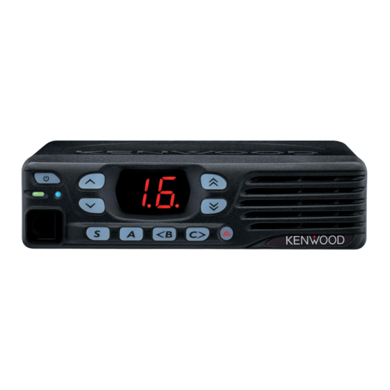
ORIENTATION FRONT AND REAR VIEWS ACC. (Power) switch Press to switch the transceiver ON or OFF. keys Press to activate their programmable functions. Display Refer to page 9. keys Press to activate their programmable functions. TX/RX Indicator Lights red while transmitting. Lights green while receiving a signal. Flashes orange when receiving an optional signaling call. -
Page 9: Display
Power input connector Connect the DC Power Cable to this connector. DISPLAY The display shows the zone/ channel number and the 2 dots show various modes of operation. Display Description Display Description Appears when a channel is Zone Display (Zone 1) removed from the scan list. -
Page 10: Basic Operation
BASIC OPERATION SWITCHING POWER ON/ OFF Press [ ] to switch the transceiver ON. Press [ ] again to switch the transceiver OFF. ADJUSTING THE VOLUME Press the key programmed as [Volume Up] to increase the volume. Press the key programmed as [Volume Down] to decrease the volume. SELECTING A ZONE AND CHANNEL Select the desired zone and channel using the keys programmed as [Zone Up]/ [Zone Down] and [Channel Up]/ [Channel Down]. - Page 11 TK-D740 TK-D840 VHF 数字车载对讲机 UHF 数字车载对讲机 用户指南 本用户指南只涵盖了您收音机的基本操作。关于经销商可能给 您的收音机添加的任何定制功能的信息,请询问您的经销商。 关于使用说明书(用户手册)的使用详情,请参阅以下 URL http://manual.kenwood.com/en_contents/search/keyword 使用之前请阅读以下信息 : 使用产品前请仔细阅读本用户指南,并请妥善保管。...
- Page 12 鸣谢惠购 我们感谢您选择 KENWOOD 作为您的数字对讲机应用程序。 目录 用户注意事项 ....................3 注意事项 ........................4 拆开包装箱并检查设备..................5 随机附件 ........................5 准备工作 ......................6 介绍 ........................8 前/后视图 ........................8 显示屏 ........................9 基本操作 ......................10 切换电源开/关 ......................10 音量调节 ........................10 选择区域和信道 ...................... 10 发射...
- Page 13 用户注意事项 ◆ 政府法律禁止在政府控制的区域内使用未经当局许可的无线电发射机。 ◆ 非法使用将会受到罚款或监禁处罚。 ◆ 只能由有资格的技术人员进行维修。 安全性: 操作人员应该知道并了解对讲机操作的一般危险。 警告 ◆ 易爆环境(气体、粉尘以及烟雾等) 在加油或者停车于加油站时,请关闭通信机。如果通信机安装在汽车的行李箱部位,请 勿将备用油箱放在行李箱内。 ◆ 射频辐射伤害 当有人站立于天线附近或触摸天线时,请勿操作通信机,以免造成射频辐射灼伤或相关 人体伤害。 ◆ 炸药起爆雷管 在距离炸药起爆雷管150米的范围以内操作通信机可能引起雷管的爆炸。当位于爆破现 场或标有“关掉双向无线电”标志的区域内时,请关闭通信机电源。如您正在使用车辆 运输雷管,务必确保将雷管装在内有衬垫的封闭式金属箱中。将雷管放入箱内或从箱中 取出时,请勿进行发射操作。 产品中有毒有害物质或元素的名称及含量 有毒有害物质或元素 部件名称 铅 汞 镉 六价铬 多溴联苯 多溴二苯醚 (Pb) (Hg) (Cd) (Cr(VI)) (PBB) (PBDE) 框架 ×...
- Page 14 码转换为人类可读形式。美国专利编号 #6,199,037, #6,912,495, #8,200,497, #7,970,606, and #8,359,197. 固件版权 JVC建伍公司保留建伍产品存储器内嵌固件的产权和版权的所有权。 注意事项 请遵照以下注意事项,以防止火灾、人身伤害和通信机损坏。 • 开车时请勿尝试配置通信机;这样做非常危险。 • 无论何种原因请勿拆卸或改装通信机。 • 请勿将本机长时间暴晒于阳光下,也不可靠近热源。 • 如发现本机发出异味或冒烟,请立即关闭通信机电源,并与您的KENWOOD经销商联系。 • 开车时使用通信机可能会违反交通法规。请查阅并遵守当地的交通法规。 • 请勿使用非KENWOOD指定的选件。 • 请不要将该设备的包装塑料袋放在小孩可以触摸到的地方。如果塑料袋盖在头上可能会 导致窒息。 • 请勿将对讲机放置在不稳定的表面上。 • 为保护听力请尽可能降低音量。 • 在连接选件前,请务必关闭对讲机的电源。 注意 ◆ 本通信机仅能在12V的负极接地系统中工作!安装通信机前请检查电池极性及车辆的 电压数值。 ◆ 只能使用随带的直流电源电线或选购的KENWOOD直流电源电线。 ◆ 请勿切断和/或移除直流电源电线上的保险丝管座。 ◆ 在电线可能被卷入机器的附近,请不要将麦克风的电线挂于颈部。 注意 为了乘客安全起见,请使用随带的安装支架和螺丝组将通信机安装牢固,以防在发生车 辆碰撞时通信机松脱。...
- Page 15 拆开包装箱并检查设备 注: ◆ 以下说明供KENWOOD经销商、经授权的KENWOOD服务机构或工厂使用。 小心拆开通信机的包装。在丢弃包装材料前,建议您先验明下表所列的物品。如果 有物品缺失或在运输过程中损坏,请立即向承运人提出书面要求。 随机附件 直流电源电线(带保险丝) ........... 1 •...
- Page 16 准备工作 警告 您车上的各种电子设备如未得到妥善保护,发射时产生的射频能量可能导致其出现故 障。典型设备包括电子燃油喷射、防抱死制动及巡航控制系统。如果您的汽车装有这些 设备,请咨询经销商车辆的制造信息。为了确定这些系统在发射时能否正常工作,应考 虑经销商的建议。 电源电线连接 注意 本通信机仅能在12V的负极接地系统中工作!安装通信机前请检查电池极性及车辆的电压 数值。 1 查找预留于隔热板上的电源电线可以穿过的小孔。 • 如果没有,请使用圆形剪钻一个孔,然后安装橡皮环。 2 使电源电线穿过隔热板进入发动机室。 3 将红色引线连接到蓄电池的正极(+)端子,将黑色引线连接到蓄电池的负极(–)端 子。 • 使保险丝位于尽可能接近蓄电池的位置。 4 用定位带将多余电线绕成盘状并固定好。 • 确保电线留有足够裕量,以便在拆下通信机进行维修时可以继续为其供电。 安装通信机 警告 为了乘客安全起见,请使用随带的安装支架和螺丝组将通信机安装牢固,以防在发生车 辆碰撞时通信机松脱。 注: ◆ 安装通信机前,请检查安装螺丝探出安装表面下的深度。钻安装孔时要小心,不要破坏汽 车的布线或零件。 1 以安装支架为样板,大致标出安装孔的位置。用4.2 mm的钻头钻孔,然后利用随 带的螺丝安装好固定支架。 • 在用户伸手可得的范围内安装通信机,并确保后面留有足够的空间用于电线连接。 2 将天线和附带的电源电线连接到通信机上。 3 将通信机滑进安装支架,并用附带的六角螺丝固定。...
- Page 17 注意 替换直流电源电线中的保险丝时,确保使用相同电流值的保险丝。切勿换用额定值更高 的保险丝。 选件麦克风 平垫 弹簧垫 M4 x 6 mm 六角螺丝 5 x 16 mm自攻螺丝 天线连接器 安装支架 电源输入连接器 黑(-)线 红(+)线 12V汽车蓄电池 直流电源电线(C型) 保险丝 黑(-)线 红(+)线 直流电源电线(M型) 保险丝...
- Page 18 介绍 前/后视图 ACC. (电源)开关 按下可开关通信机。 键 按下可启动其可编程功能。 显示屏 请参阅第9页。 键 按下可启动其可编程功能。 发射/接收指示灯 发射时亮红色。接收信号时亮绿色。接收可选信令呼叫时闪烁橙色。 麦克风插孔 将麦克风插头插入该插孔。 状态指示灯 根据经销商的编程设置,在指定的模式期间点亮。 键 S / A / <B / C> / 按下可启动其可编程功能。 扬声 内部扬声器。 PTT开关 按下此开关,然后对着麦克风讲话,可呼叫某个电台。 天线连接器 将天线连接到此连接器上。...
- Page 19 ACC连接器 通过KCT-60将ACC连接到该连接器上。 外部扬声器插孔 将外部扬声器连接到该插孔上。 电源输入连接器 将直流电源电线连接到该连接器上。 显示屏 显示区域/信道号码,两个点指示各种操作模式。 显示 说明 显示 说明 从扫描列表中删除信道时出现。 显示区域(区域1) (cd) 启动单独工作者功能时出现。 显示信道(信道16) (Ln) 扫描过程中出现。(Sc) 发送数据过程中出现。(dt) 通信机被遥毙中出现。(St) 频道繁忙过程中出现。 打开通信机电源时出现。通信机 选信道为优先信道。(P) 密码函数被编程。(PS) 静噪级别设置功能开启时出现。 扰频器功能开启时出现。(Sr) (SL) 时出现扰频器/加密代码模式处于 网通信功能开启时出现。(tA) 打开状态。(co) 喇叭提示功能开启时出现。 信息完成时出现。(Ed) (HA) 车外扩音功能开启时出现。 当呼叫中断功能启用时显示。 (PA) (It) AUX功能开启时出现。(AU) 选择外接扬声器时出现。(SP) 向扫描列表中添加信道时出现。...
- Page 20 基本操作 切换电源开/关 按可[ ]打开通信机电源。 再按[ ]一下将关闭通信机电源。 音量调节 按 [ 音量上调 ] 键可提高音量。按 [ 音量下调 ] 键可降低音量。 选择区域和信道 请利用设置为 [ 区域上调 ]/[ 区域下调 ] 和 [ 信道上调 ]/[ 信道下调 ] 的键选择所需的 区域和信道。 • 显示屏上将出现“G1”(区域1)/“16”(信道16)字样。 发射 1 选择想要的区域和信道。 2 按下设置为[监听]或[静噪打开]的键,检查信道是否空闲。 • 如果信道繁忙,请等待直至信道空闲。 3 按PTT开关并对着麦克风讲话。松开PTT开关将转换到接收状态。...