
Related Manuals for D-Link DP-100


Summary of Contents for D-Link DP-100
-
Page 1: Print Server
Model DP-100 Multiprotocol Ethernet Print Server Hardware User’s Guide Rev. 01 (May, 1997) 6DP100H.001 Printed In Taiwan RECYCLABLE... -
Page 3: Wichtige Sicherheitshinweise
Wichtige Sicherheitshinweise Bitte lesen Sie sich diese Hinweise sorgfältig durch. Heben Sie diese Anleitung für den spätern Gebrauch auf. Vor jedem Reinigen ist das Gerät vom Stromnetz zu trennen. Vervenden Sie keine Flüssig- oder Aerosolreiniger. Am besten dient ein angefeuchtetes Tuch zur Reinigung. Um eine Beschädigung des Gerätes zu vermeiden sollten Sie nur Zubehörteile verwenden, die vom Hersteller zugelassen sind. -
Page 4: Limitation Of Liability
RANGE OF THE INTENDED USE, OR BY ACCIDENT, FIRE, LIGHTNING OR OTHER HAZARD. LIMITATION OF LIABILITY IN NO EVENT WILL D-LINK BE LIABLE FOR ANY DAMAGES, INCLUDING LOSS OF DATA, LOSS OF PROFITS, COST OF COVER OR OTHER INCIDENTAL, CONSEQUENTIAL OR INDIRECT... -
Page 5: Limited Warranty
Customer bear the cost of sending back such products. A service charge may or may not be levied to Customer by D-Link. To find out if a service charge is levied or not, and the charged amount, read the RMA that is returned to Customer, or ask the D-Link office when an RMA is requested. - Page 6 D-Link Offices to Contact for Warranty Service: To obtain an RMA number for warranty service, contact the D-Link office nearest you. A list of contact addresses for D-Link’s international offices is found in the back of this User’s Guide. Your Warranty...
-
Page 7: Copyright Statement
Trademarks Copyright 1997 D-Link Corporation. Contents subject to change without prior notice. D-Link is a registered trademark of D-Link Corporation/D-Link Systems, Inc. All other trademarks belong to their respective proprietors. Copyright Statement No part of this publication may be reproduced in any form or by any means... -
Page 9: Table Of Contents
ABLE OF BOUT UIDE ... 1 NTRODUCTION DP-100 Print Server Features ...1 External Features ...3 Port Connectors ... 3 Network Cable Connectors ... 4 DC Power Connector ... 4 LED Indicators ... 4 NPACKING AND NSTALLATION Unpacking and Inspecting the Print Server...6 Installing the DP-100...7... - Page 10 Environmental and Physical ... 12 ... 14 INOUTS Parallel Ports ... 14 Serial Port ... 15 ... 15 NDEX About This Guide...
-
Page 11: About This Guide
For information about software configuration of the DP-100 to allow it to be used with your network, consult the Print Server Administration User’s Guide included with your DP-100. -
Page 13: Introduction
DP-100 Multiprotocol Ethernet Print Server User’s Guide NTRODUCTION The DP-100 Print Server is a compact print server which connects to your Ethernet network anywhere you wish to locate printer services. It manages the flow of print files from your workstations or file servers to its connected printers, delivering print jobs to high-performance printers much faster than a file server or a PC acting as a print server can. - Page 14 The DP-100 picks up the workload of managing print file traffic to its connected printers. This provides workload relief to your file servers, and allows the file servers' full capacity to be used for file access or other direct services to network users. On peer-to-peer networks, workstations can print directly to the DP-100 without increasing the load of another workstation or server.
-
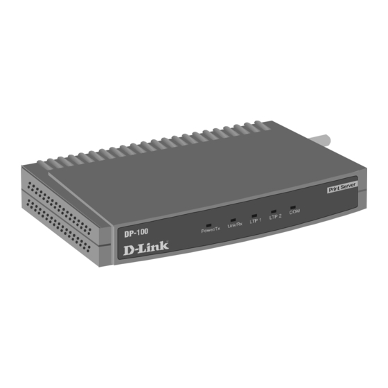
Page 15: External Features
This section describes the externally visible features of the DP-100 print server. Port Connectors The DP-100’s three printer ports are located on its rear panel. Two identical parallel ports are labeled LPT1 and LPT2; the single serial port is labeled COM. These printer ports are independently configurable using the PS Admin program or the print server’s... -
Page 16: Network Cable Connectors
10Base2 cabling (using a BNC connector). Both of these network cable connectors are located on the DP-100’s right side panel. DC Power Connector The DC power input connector is located on the DP-100’s right side panel and is labeled DC 12V. Figure 1 -3 Print Server Right Side Panel... - Page 17 DP-100 Multiprotocol Ethernet Print Server User’s Guide The indicator blinks off briefly to indicate that the DP-100 is transmitting to the network. Link/Rx Steady or flashing green confirms that the DP-100 has a good connection to the Ethernet network. The indicator blinks off briefly to indicate that the DP-100 is receiving from the network.
-
Page 18: Unpacking And Installation
This chapter explains how to install your DP-100 print server and connect it to the network. It also describes the print server self test indications, and tells how to wall-mount your print server. Unpacking and Inspecting the Print Server Carefully remove all items from the package. In addition to this Hardware User’s Guide, be certain that you have:... -
Page 19: Installing The Dp-100
5. While each printer is powered off, connect its tested and confirmed port with a like printer port of the DP-100. If you are connecting fewer than three printers, then keep in mind that parallel- port connections are preferred for high-performance printers. -
Page 20: Power On Self-Test
DP-100’s self-test will proceed. Power On Self-Test When the DP-100 is powered on, it automatically performs a self-test on each of its major components. The final result of the self-test is signaled by the state of the LPT1, LPT2, and COM LED indicators following the self- test. -
Page 21: Testing Your Dp-100
DP-100 to a wall or partition adjacent to your printers. To mount the DP-100 with the front panel facing up (and the printer port connectors facing down), set the two mounting screws at the lower-left and... - Page 22 443 PP When setting the screws into the wall or partition, leave about 3 mm ( between the head of each screw and the wall surface. Then place the DP- 100 so that the mounting sockets on the bottom of its case fit over the two screws.
-
Page 23: Roduct Pecifications
DP-100 Multiprotocol Ethernet Print Server User’s Guide RODUCT PECIFICATIONS Printer Connection Standards: IEEE 1284 bi-directional parallel interface, RS-232 Ports: Bi-directional 25-pin parallel ports 2, 9-pin DTE serial port Parallel Port Bi-directional Communication: Hewlett-Packard PJL (Printer Job Language) supported Network Connection Network Standards: IEEE 802.3 10BASE2/10BASE-T Ethernet... -
Page 24: Network Protocols
Network Protocols Ethernet Frame Types: 802.2, 802.3, Ethernet II, SNAP (auto-switching) Transport Protocols: IPX/SPX, TCP/IP, NetBEUI, AppleTalk/EtherTalk TCP/IP Protocols Supported: BOOTP, SNMP, Telnet, TFTP, FTP, lpd Management and Diagnostics Standard: SNMP MIBs: MIB-II (RFC 1213) Diagnostic LED Indicators: Power/Tx, Link/Rx, LPT1, LPT2, COM Environmental and Physical Power Supply: External power supply providing 12VDC/ 500mA Dimensions: 190mm... - Page 25 DP-100 Multiprotocol Ethernet Print Server User’s Guide Safety: UL (UL 1950), CSA (CSA950), TUV/GS (EN60950) Product Specifications...
-
Page 26: Port Pinouts
This appendix shows the pinouts of the DP-100 parallel and serial printer ports. Parallel Ports The following table lists the pinouts of the print server’s 25-pin parallel port connector (identical to the connector used on most personal computers), as well as the 36-pin Centronics connector used on most printers. -
Page 27: Serial Port
DP-100 Multiprotocol Ethernet Print Server User’s Guide 25-pin Centronics 18-25 16, 17, 19-30 Serial Port The table below shows the pinout of the print server’s 9-pin RS-232 serial port. The print server’s serial port is a DTE (Data Terminal Equipment) port, and should be connected to a DCE (Data Communications Equipment) serial port on your printer. - Page 28 10Base2...4, 7 10Base-T ...4, 7 COM...3 COM LED ...5, 9 DC power adapter...6, 8 IEEE 1284 ...2 Link/Rx LED...5 LPT1...3 LPT1 LED ...5, 9 LPT2...3 LPT2 LED ...5, 9 network connectors ...4 packing list ... 6 pinout parallel port ... 14 serial port ...
- Page 29 2180 Dunwin Drive, Unit # 6, Mississauga Ontario, L5L 5M8, Canada TEL: 1-905-828-0260 FAX: 1-905-828-5669 U.K. D-LINK (EUROPE) LTD. D-Link House, 6 Garland Road, Stanmore, London HA7 1DP U.K. TEL: 44-181-2355555 FAX: 44-181-2355500 GERMANY D-LINK (DEUTSCHLAND) GMBH I.G. Bachstrae 22, 65830 Kriftel Germany...
-
Page 31: Registration Card
3. What network protocol(s) does your organization use ? †XNS/IPX †TCP/IP †DECnet †Others_____________________________ 4. What network operating system(s) does your organization use ? †D-Link LANsmart †Novell NetWare †NetWare Lite †SCO Unix/Xenix †PC NFS †3Com 3+Open †Banyan Vines †DECnet Pathwork †Windows NT †Windows NTAS †Windows '95 †Others__________________________________________ 5.