
Related Manuals for ABB AK102


Summary of Contents for ABB AK102
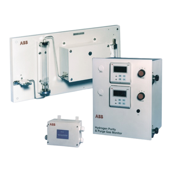
- Page 1 Gas Analyzer Systems for User Guide Hydrogen-cooled Alternators IM/AK1/23_1 AK102 and AK103...
-
Page 2: Electrical Safety
We are an established world force in the design and manufacture of instrumentation for industrial process control, flow measurement, gas and liquid analysis and environmental applications. As a part of ABB, a world leader in process automation technology, we offer customers Cert. No. Q 05907 application expertise, service and support worldwide. - Page 3 CONTENTS OPERATION ............... 25 INTRODUCTION ............2 Normal .............. 25 DESCRIPTION .............. 3 9.1.1 Purging of Hydrogen Coolant Gas ..25 Model 6553 Display Unit ........3 9.1.2 Filling with Hydrogen Coolant Gas ..25 2.1.1 Range Display ........3 Range 1 Operating Page ........
- Page 4 The ultimate responsibility for any particular installation lies with the installing user/contractor. This manual gives the installation, operating and maintenance information for the Company's range of Models AK102 and AK103 Intrinsically Safe Gas Analyzer Systems, normally used with hydrogen cooled electrical power generators.
-
Page 5: Range Display
An alarm output and a zero adjustment – see Fig. 2.1. retransmission signal (4 to 20mA) are provided for The AK102 version is a dual 3-range instrument, designed to this switch position only. provide 100% redundancy. Position (2) Percentage of Hydrogen in CO /Argon by volume. - Page 6 …2 DESCRIPTION 2.2 Model 006540203 or 006548000 2.3 Model 4234 500/4234 501 Katharometer Analyzer Panel – Fig. 2.2 Power Supply Units (PSU) – Fig. 3.3 Each panel comprises a metering valve, a drying chamber, a Caution. Do not connect the mains supply to the PSU thermally lagged katharometer (Model 006539 or 006548) and a with the output terminals open circuit.
- Page 7 N4006 Manufactured by: A B B L i m i t e d Oldends Lane, Stonehouse, Glos. England GL10 3TA ABB L i m i t e d Oldends Lane, Stonehouse, Glos. England GL10 3TA Model No. Type No. Unique Serial No.
- Page 8 Year Manuf. N4006 Manufactured by: A B B L i m i t e d Oldends Lane, Stonehouse, Glos. England GL10 3TA ABB Limited Oldends Lane, Stonehouse, Glos. England GL10 3TA TYPE 4234500/501 POWER SUPPLY UNITS ll (1)G 0600 Intrinsic [EEx ia] llC (–20CTa55C)
- Page 9 3 PREPARATION 3.1.4 AK100 Ordering Information a i l y t i & y t i y t i y t i v i t v i t ) y l ) i s & a l f ) i s ) i s h t i h t i...
-
Page 10: Mechanical Installation
4 MECHANICAL INSTALLATION 4.1 Locating and Mounting System Items 4.1.1 Models AK102 and AK103 Display Unit – Fig. 4.1 Note. The display unit be located in the area of the application plant in a sheltered interior environment. must safe The display unit is designed for panel mounting in a position to suit reading of the displays and with access to the rear for electrical wiring interconnections. - Page 11 4 MECHANICAL INSTALLATION… 4.1.2 Katharometer Analyzer Panel – Fig. 4.2 Note. The panel is located in the hazardous area (Zone 0, 1 or 2) of the application plant in a sheltered interior environment. Avoid a location that subjects the katharometer unit to direct sunlight. When two katharometer panels are used locate them in positions that have the same ambient temperature.
- Page 12 …4 MECHANICAL INSTALLATION 4.1.3 Model 4234 Power Supply Unit – Fig. 4.3 Note. The unit be located in the area of the application plant in a sheltered interior environment. must safe The power supply unit has four fixing lugs for mounting on a suitable vertical surface. The installation dimensions are shown in Fig. 4.3. Dimensions in mm (in.) Ensure a clearance of at least 100 (4) at both ends of the unit for acces to the cable...
- Page 13 (not fitted to those systems that Cubicle sealed to IP55 require 100% redundancy) Weight of cubicle assembly 56kg (123lb) max. Note. Isolator and MCBs not fitted to AK102 versions (can be fitted to AK103 versions if specified). Fig. 4.4 Installation Dimensions – Cubicle...
- Page 14 …4 MECHANICAL INSTALLATION 4.2 Sample Gas Interconnections Note. A hazardous mixture of hydrogen in air could develop in the event of leakage from the sample gas system. Mount katharometer analyzer panels in a ventilated area. The sample pressure must not exceed 0.35 bar (Gauge) for Model 6540 203 or 10 bar (Gauge) for Model 6548 000. The incoming sample gas temperature must not exceed 55°C (131°F).
-
Page 15: Electrical Installation
5 ELECTRICAL INSTALLATION 5.1 Electrical Interconnections – Fig. 5.1 Fig. 5.1 System Diagram... - Page 16 TB4 not fitted Terminal Block (TB5 & TB6) to AK103 to AK103 Power and Signal for Katharometer Zero Pots. Conventional Circuits Intrinsically Safe Circuits Fig. 5.2 Location of Components Inside Case (Rear View) – Models AK102 & AK103 Display Units...
- Page 17 5 ELECTRICAL INSTALLATION…...
- Page 18 …5 ELECTRICAL INSTALLATION...
- Page 19 5 ELECTRICAL INSTALLATION… Caution. The integrity of the fail-safe operation of the zener diode safety barrier devices depends on a Safety Earth connection which must not have a resistance greater than 1 to the application plant earth (gr ound). Make the Earth (Ground) and Safety Earth connection at the stud (TS1) – see Fig. 5.2. On completion of wiring and checks, replace the outer case and secure the clamping brackets to the mounting panel.
- Page 20 …5 ELECTRICAL INSTALLATION 5.1.3 Model 4234 Power Supply Unit – Fig. 5.6 Caution. Do NOT connect mains supply to the power supply unit with the output terminals on open circuit. Note. Ensure that the power supply unit is correct for the mains supply voltage available. A nominal 115V unit cannot be adapted for use with a nominal 230V supply or vice versa.
- Page 21 5 ELECTRICAL INSTALLATION 5.2 Intrinsically Safe Requirements 5.2.2 Recommended Cables These requirements relate to the interconnecting wiring made to The choice of wiring cable is restricted by the limitations and from Model 6540 203 and 6548 000 Katharometer Analyzer imposed by the certification parameters. Care must be taken to Panels in the hazardous area and those for remote ancillary ensure that the specification of the cable required for items connected to the system.
- Page 22 6 SETTING UP 6.1 Katharometer Analyzer Panel – 6.2 Setting Sample Flow Filling the Drying Chamber – Fig. 6.1 When all tubing interconnections have been made and external 1) Remove the drying chamber on the katharometer analyzer parts of the sample system checked for leaks, carry out the panel by unscrewing the large knurled nut at the base of the following procedure: chamber.
- Page 23 6 SETTING UP 6.3 Electrical Checks 6.3.2 Zener Diode Safety Barrier Devices Carry out the electrical checks detailed in Sections 6.3.1 and The zener diode safety barrier devices (MTL7755ac or 6.3.2. MTL7055ac) in the 6553 Display Unit are checked at the time of manufacture.
-
Page 24: Controls And Displays
7 CONTROLS & DISPLAYS 7.1 Displays – Fig. 7.1 7.2 Switch Familiarization – Figs. 7.1 and 7.2 The display mounted in the 6553 panel comprises a 5-digit, 7- segment digital upper display line and a 16-character dot-matrix Advance to lower display line. The upper display line shows actual values of next page hydrogen purity, hydrogen in air, air in carbon dioxide, alarm set Page 1... -
Page 25: Instrument Start-Up
8 START-UP 8.3 Electrical Calibration Warning. When the apparatus is connected to its The instrument is factory calibrated for electrical voltage signal supply, terminals may be live and the opening of covers input. No adjustment is normally necessary for correct or removal of parts (except those to which access may functioning of the display unit. - Page 26 …8 START-UP 8.4 Gas Calibration 8.4.1 Introduction 8.4.2 Gas Range Calibration Before putting the system on-line, it is recommended that a Note. Test for leaks in accordance with the calibration check for the 'zero' reading is made using calibration requirements of the responsible authority for site safety standard sample gas.
-
Page 27: Operation
9 OPERATION 9.1 Normal 9.1.2 Filling with Hydrogen Coolant Gas During normal operation the AK100 Gas Analyzer System is This procedure is a reversal of the purging procedure. used to indicate the purity of hydrogen used as a coolant. The Initially, inert purge gas (CO or argon) is introduced into the display shows the percentage of hydrogen in air, which should... - Page 28 9 OPERATION… 9.2 Range 1 Operating Page Range 1 is selected for normal operations and the indicates the purity of the hydrogen used as a coolant. The alarm Operating Page set points can be viewed but not altered. To change the alarm set points or program other parameters, refer to Section 10. Hydrogen Purity Shows the percentage of hydrogen in air.
- Page 29 …9 OPERATION Notes. • Access to the programming pages is possible only with Range 1 selected. • The following programming pages apply to display units. both Range 1 Selected Access to Secure Parameters Note. All parameter values shown on the upper SECURITY CODE display line are the default settings.
-
Page 30: Access To Secure Parameters
10 PROGRAMMING Note. Access to the programming pages is possible only with Range 1 selected. 10.1 Access to Secure Parameters A 5-digit code is used to prevent unauthorized access to the secure parameters. Security Code Enter the required code number, between 00000 and 19999, to gain access to the secure parameters. -
Page 31: Set Up Outputs Page
…10 PROGRAMMING 10.3 Set Up Outputs Page Note. Access to the programming pages is possible only with Range 1 selected. SET UP OUTPUTS Alarm 1 Set Point The set point band is defined as the actual value of the set point plus or minus the hysteresis value. -
Page 32: Electrical Calibration Page
10 PROGRAMMING… 10.4 Electrical Calibration Page Note. Access to the programming pages is possible only with Range 1 selected. Notes. 1) The 4689 instruments incorporate a two point calibration sequence requiring both zero and span inputs for a calibration. It is not possible to adjust the range zero or the range span scale points independently. -
Page 33: Maintenance
11 MAINTENANCE 11.2 Diagnostic Tests The katharometer unit and its associated equipment are designed for stable and accurate operation over long periods. Warning. • Each of the units in the system are part of the This section covers the requirements for fault finding, diagnostic certified intrinsically safe system. - Page 34 …11 MAINTENANCE 11.3.3 Changing Desiccant in Drying Chamber 11.4 Repair Maintenance The need to change the desiccant in the drying chamber on 11.4.1 Removing Liquid from the katharometer Analyzer panel depends on the condition Katharometer Measurement Block – Fig. 11.1 of the sample gas.
-
Page 35: Spare Parts List
12 SPARE PARTS LIST …11 MAINTENANCE o) Isolate the katharometer unit at its PSU. Warning. Interference with any unit or its components implies acceptance of responsibility by that person for p) Make the remaining electrical connections at TB1 of the ensuring the continuing maintenance of intrinsic safety katharometer unit –... -
Page 36: Specification
Sheltered interior, 0 to 90% RH Retransmission No. of retransmission signals AK101 – Two fully isolated (One for H Purity, One for Purge Gas) AK102 – Two fully isolated AK103 – One fully isolated AK104 – One fully isolated (H Purity) Output current... - Page 37 13 SPECIFICATION 4234 Power Supply Unit 6540–203 and 6548–000 Katharometer Analyzer Panel Approvals Approvals CENELEC approved [EEx ia] IIC T –20“C to +55“C CENELEC approved EEx ia IIC T –20“C to +55“C BASEEFA Certificate No. BAS 01 ATEX 7041 II (1)G BASEEFA Certificate No.
- Page 38 NOTES...
-
Page 39: Customer Support
Chemical & Pharmaceutical – Food & Beverage United Kingdom – Manufacturing – Metals and Minerals ABB Limited – Oil, Gas & Petrochemical Tel: +44 (0)1453 826661 – Pulp and Paper Fax: +44 (0)1453 829671 Drives and Motors United States of America •... - Page 40 ABB has Sales & Customer Support The Company’s policy is one of continuous product improvement and the right is reserved to modify the expertise in over 100 countries worldwide information contained herein without notice. www.abb.com Printed in UK (06.04) © ABB 2004 ABB Limted ABB Inc.