Table of Contents

Related Manuals for Siemens SIMOSEC


Summary of Contents for Siemens SIMOSEC
- Page 1 Medium Voltage Switchgear Type SIMOSEC up to 27 .6 kV, Extendable, Metal-Enclosed up to 1200 A Medium Voltage Switchgear OPERATING INSTRUCTIONS Description Installation Operation Maintenance Order no.: 832-6063.0 Revision:...
- Page 2 Qualified Person Siemens Energy, Inc. The warranty contained in the contract between the parties is the sole warranty of Siemens Energy, Inc. For the purpose of this manual and product labels a qualified per- Any statements contained herein do not create new warranties or son is one who is familiar with the installation, construction, or modify the existing warranty.
-
Page 3: Table Of Contents
........39 19.5 Switching the three-position switch to GROUNDED position ........77 Installing the panels ........44 19.6 Switching the three-position switch from 12.1 Installing the end wall ........44 GROUNDED to OPEN position .......79 832-6063.0 * OPERATING INSTRUCTIONS SIMOSEC * REVISION 02... - Page 4 100 25.3 Checking the fuse tripping mechanism..100 25.4 Installing the HV HRC (current limiting) fuses ............102 25.5 Completing fuse replacement...... 102 Switchgear recycling ........103 Help.............. 103 Index ............104 REVISION 02 * OPERATING INSTRUCTIONS SIMOSEC * 832-6063.0...
-
Page 5: Safety Instructions
Safety instructions Safety instructions Introduction The SIMOSEC medium voltage metal-enclosed switchgear is designed to meet all the applicable ANSI, NEMA and IEEE standards, or the applicable IEC standards, as appropriate for the specific contract. Successful application and operation of this equipment depends as much upon proper installation and maintenance by the user as it does upon the careful design and manufacture by Siemens. -
Page 6: Dangerous Procedures
Siemens equipment, processes and systems. Contact regional service centers, sales offices or the factory for details, or telephone Siemens Field Service at 1-800-347-6659 (919-365-2200 outside the U.S.). -
Page 7: Description
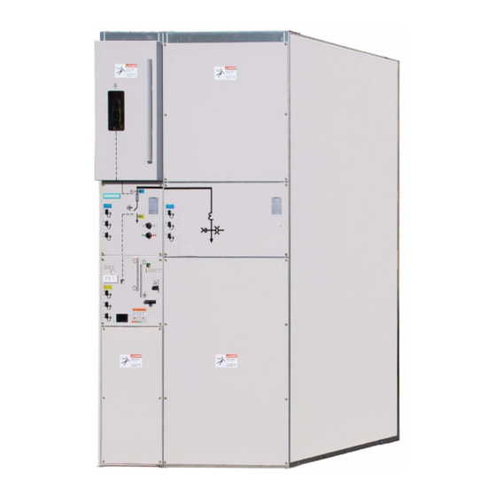
Metering panel Fuse switch panel SIMOSEC switchgear is used for power distribution in systems up to 27 .6 kV: • for customer substations, distribution substations and switching substations of utilities • in public buildings such as high-rise buildings, airports, hospitals, sports arenas •... - Page 8 • Provisions for extension and replacement (modular switchgear concept) • Installation and extension without SF gas work • Long service life of switching devices • Standardized protection and control equipment • Ecological manufacture and utilization/recycling REVISION 02 * DESCRIPTION SIMOSEC * 832-6063.0...
-
Page 9: Panel Versions
(with three-position switch) motor operating mechanism for three-position switch Pressure relief device for switching device Option: HV HRC (current limiting) fuse Locking device for three-position switch Post insulator Cable compartment cover/ door Low voltage compartment 832-6063.0 * DESCRIPTION SIMOSEC * REVISION 02... -
Page 10: Components
Description Components For further information about modules or components of your SIMOSEC switchgear, please refer to the medium voltage switchgear catalog. Three-position switch-disconnector The three-position switch-disconnector is designed to break normal currents of up to 600 A and to ground the feeder cables of the panel. -
Page 11: Operating Mechanisms For The Three-Position Switches
Before the switch can be re- closed, the switch must be operated to the ’’GROUNDED“ position to allow for correc- tion of the problem that led to the tripping action. 832-6063.0 * DESCRIPTION SIMOSEC * REVISION 02... - Page 12 Fig. 6: Spring-operated mechanism Fig. 7: Spring-operated/stored-energy mechanism Operating mechanism for three-position switch- Switch position indicator (mechanical) disconnector with optional motor operating mechanism Manual operation of detachable lever mechanism for the grounding Spring function REVISION 02 * DESCRIPTION SIMOSEC * 832-6063.0...
- Page 13 Switch positions of the three-position switch Three-position switch-disconnector Switch up to 600 A position CLOSED OPEN GROUNDED Fig. 8: Switch positions of the three-position switch Bus bar connection Feeder, e.g., for cable connection 832-6063.0 * DESCRIPTION SIMOSEC * REVISION 02...
- Page 14 Switch-positions of the make-proof grounding switch Make-proof grounding switch Switch positions OPEN GROUNDED Fig. 9: Switch-positions of the make-proof grounding switch Bus bar connection Feeder, e.g., for cable connection (option) or for metering (option) REVISION 02 * DESCRIPTION SIMOSEC * 832-6063.0...
-
Page 15: Current And Voltage Transformers
• Single-pole indoor block-type current transformer • Single-pole indoor voltage transformer • Cast-resin insulated • Secondary connection by means of screw-type terminals • 1A or 5A CT secondary rating, to suit order requirement 832-6063.0 * DESCRIPTION SIMOSEC * REVISION 02... -
Page 16: Protection And Control Equipment
Momentary-contact rotary control switch (spring-return) Fig. 12: Control panel section The local-remote switch latches (non-spring-return) in the corresponding switch position. LOCAL position: REMOTE position: Local operation Remote operation from the control room/monitoring station REVISION 02 * DESCRIPTION SIMOSEC * 832-6063.0... -
Page 17: Hv Hrc (Current Limiting) Fuse Assembly
The HV HRC (current limiting) fuse assembly protects downstream cable runs and/or devices. The fuses used in SIMOSEC switchgear are manufactured by Bussman. The fuses comply with IEC 60282-1 and ANSI/IEEE C37 .41. They are a general purpose current limiting fuse. The time-current characteristics of the fuses comply with the parameters for E-rated fuses as defined by ANSI C37 .46. - Page 18 Fig. 14: Principle of fuse tripping Striker pin not tripped (fuse intact) Striker pin tripped (fuse blown) REVISION 02 * DESCRIPTION SIMOSEC * 832-6063.0...
-
Page 19: Interlocks
"CLOSED" position. Locking device The control gate of the three-position switch-disconnector and the three-position disconnector can be locked in all three switch positions. ONLY GROUNDING/DE-GROUNDING SWITCHING NOT POSSIBLE ONLY OPENING/CLOSING POSSIBLE POSSIBLE 832-6063.0 * DESCRIPTION SIMOSEC * REVISION 02... - Page 20 Description FII-Protection-System (option) The Fuse-Installed-Intact-Protection-Sytsem (FII-Protection-Sytsem) prevents moving the three-position switch to CLOSED position if any fuse is blown or not installed. Fig. 15: Shuttter of FII-Protection-Sytsem REVISION 02 * DESCRIPTION SIMOSEC * 832-6063.0...
-
Page 21: Bus Bars
Applicable cable types are described in Section "Cable terminations" (see Description, Page 34). Installation of high voltage cables is described specifically for each panel in the operating Instructions (see “Connecting high voltage cables” on page 53). * Larger connection cross-sections on request. 832-6063.0 * DESCRIPTION SIMOSEC * REVISION 02... -
Page 22: Rating Plates
Test mark for performed acceptance test (pressure test) of the vessel Order number of operating instructions Fig. 17: Rating plate on the control panel Fig. 18: Rating plate in the operating mechanism box REVISION 02 * DESCRIPTION SIMOSEC * 832-6063.0... -
Page 23: Ready-For-Service" Indicator For Sf Gas
42), then: • Do not energize the switchgear • Do not operate the switchgear • Contact the Siemens Field Service (see “Field Service Operation” on page 6). Features • Easy to read • Self-monitoring •... -
Page 24: Voltage Detection Systems
Voltage detection system via capacitive voltage divider (phase L3 shown) HR indicator, plug-in type • -C1: capacitance integrated into bushing or post insulator • -C2: capacitance of the connection leads and of the voltage indicator to ground REVISION 02 * DESCRIPTION SIMOSEC * 832-6063.0... -
Page 25: Accessories
• Does not require auxiliary power 8.12 Accessories Standard accessories: • SIMOSEC documentation (operating and installation instructions) • Operating lever for three-position switch/ grounding switch (black grip) Further accessories according to order documentation/purchase order (selection): • Operating lever for three-position switch (black grip) •... - Page 26 Description Fig. 24: Functional tester (Horstmann type HO-ST) • Phase comparison test units (e.g., make Pfisterer, type EPV) Fig. 25: Electronic phase comparer REVISION 02 * DESCRIPTION SIMOSEC * 832-6063.0...
-
Page 27: Technical Data
Reference dimension "e" Bus bar grounding panel type BG Rated voltage U [kV] 8.25 27.6 Rated fault closing current, I kA(asym) 32 40 32 40 22 up to 52 65 52 65 52 [kA]peak 832-6063.0 * DESCRIPTION SIMOSEC * REVISION 02... -
Page 28: Tightening Torques
The fuse assembly is designed for a reference dimension "e" = 537 mm. With reference dimension "e" = 442 mm, an extension tube (95 mm long) is required. Tightening torques If not stated otherwise, the following tightening torques apply to SIMOSEC switchgear: Joint: Thread... -
Page 29: Protection Against Solid Foreign Bodies, Electric Shock And Ingress Of Water
Description Protection against solid foreign bodies, electric shock and ingress of water The medium voltage switchgear SIMOSEC complies with the following degrees of protection: Degree of Type of protection Application protection IP2X Protection against solid foreign bodies: Enclosure of live parts Protected against the penetration of solid foreign bodies;... -
Page 30: Standards And Guidelines
ADR, Section 1.1.3.1 b. Type of service location SIMOSEC switchgear can be used in an indoor installation in accordance with IEC 61 936 (Power installations exceeding AC 1kV) and VDE 0101 and the NEC: • Outside lockable electrical service locations at places which are not accessible to the public. -
Page 31: Service Conditions
For application is other than ’’usual service conditions“ defined by ANSI/IEEE C37 .20.3, Consult Siemens. SIMOSEC switchgear is largely insensitive to climate and ambient conditions by virtue of the following features: • No cross insulation between phases • Metal enclosure of switching devices (e.g. three-position switch) in gas-filled stainless- steel switchgear vessel •... -
Page 32: Insulating Capacity And Site Altitude
15 kV switchgear rated voltage -------------------- = 118 kV 95.0 kV rated lightning impulse withstand voltage 1.1 * 0.73 Result: According to the above table, switchgear for a rated voltage of 27.6 kV should be selected. REVISION 02 * DESCRIPTION SIMOSEC * 832-6063.0... -
Page 33: Three-Position Switch-Disconnector
Selection of HV HRC (current limiting) fuses Allocation of HV HRC fuses and transformers The fuses used in SIMOSEC switchgear are manufactured by Bussmann. The fuses comply with IEC 60282-1 and ANSI/IEEE C37 .41. They are a general purpose current limiting fuse. -
Page 34: Cable Terminations
2250 mm / 2250 mm / 2250 mm / 88.6" 88.6" 88.6" 88.6" 88.6" For actual dimensions, please remark the dimension drawings. Principle of cable connection Fig. 27: Drawing of the principle of cable connections REVISION 02 * DESCRIPTION SIMOSEC * 832-6063.0... -
Page 35: Installation
Receiving Each transport unit of type SIMOSEC metal-enclosed switchgear is securely blocked and braced for shipment. It is crated, boxed, or covered as required by shipping conditions. Whatever method of shipment, every precaution is taken to insure its safe arrival. lf special handling is required, it is so indicated. - Page 36 Do not let the shipment be signed for by the consignee or his agent, if the driver will not sign the delivery receipt with damage noted. Notify the Siemens sales office immediately of any damage. Arrange for a carrier inspection of damage immediately.
- Page 37 Siemens control. lf the procedure outlined above is not followed by the consignee, purchaser, or his agent, Siemens cannot be held liable for repairs. Siemens will not be held liable for repairs in any case where the work was performed prior to authorization from Siemens.
- Page 38 • Shim plates for adapting for floor unevenness 0.02 - 0.04 in (0.5 - 1.0 mm) or as needed • Household cleaner • Suitable movable lifting device • Roller crowbars • Transport rollers REVISION 02 * INSTALLATION SIMOSEC * 832-6063.0...
-
Page 39: Unloading The Switchgear And Transporting To The Place Of Installation
Transport units with switchgear end walls are equipped with the special lifting device. For transport with a fork-lift truck the transport unit is lifted by means of two carrying rods (not furnished) which are fitted through the lifting device holes. 832-6063.0 * INSTALLATION SIMOSEC * REVISION 02... - Page 40 • Reinstall the bolts (protection against electric shock and foreign bodies). Transport at site without wooden pallet If the transport unit cannot be lowered directly onto its mounting position, please proceed as follows: REVISION 02 * INSTALLATION SIMOSEC * 832-6063.0...
- Page 41 Store SIMOSEC equipment indoors. Provide an adequate covering and place a heat source of approximately 100 watts output within each panel to prevent condensation if it is to be kept in a humid or unheated area. 832-6063.0 * INSTALLATION SIMOSEC * REVISION 02...
- Page 42 Screwdriver in cutout of the red/green plastic disc Push the small lever of the microswitch and keep it in this position, then turn the red/ green plastic disc carefully downwards until the pointer is in the green; keep this position. REVISION 02 * INSTALLATION SIMOSEC * 832-6063.0...
- Page 43 If the magnet is positioned exactly on the lower mark, the gas pressure is correct. Fig. 32: Magnet positioned on the lower mark Fasten the front cover to close the front side of the panel. 832-6063.0 * INSTALLATION SIMOSEC * REVISION 02...
-
Page 44: Installing The Panels
Align the end wall with the panel frame. Secure the end wall to the frame of the panel with the bolts provided. Installing right end wall The right end wall is mounted in a similar manner. REVISION 02 * INSTALLATION SIMOSEC * 832-6063.0... -
Page 45: Aligning The Panel And Fastening To The Foundation
Base frame of the panel Sill channel Insert Foundation Washer (inner diameter 10.5 mm, outer diameter 31.5 mm) Screw with contact washer Fig. 34: Bolting to sill channel Fig. 35: Bolting to foundation inserts 832-6063.0 * INSTALLATION SIMOSEC * REVISION 02... -
Page 46: Aligning And Joining Another Panel
Establish the same level (0.04 in/yd (1 mm/m)) using shims Align the panel in horizontal and vertical position. Foundation Aligned panel Next panel shims 0.02 - 0.04 in (0.5 - 1.0 mm) Fig. 36: Alignment and levelling of panels REVISION 02 * INSTALLATION SIMOSEC * 832-6063.0... - Page 47 Rear wall Connecting link Bolting point Fig. 38: Joining rear walls (for free-standing arrangement only) Bolt the connecting link onto the rear walls. 832-6063.0 * INSTALLATION SIMOSEC * REVISION 02...
-
Page 48: Installing The Bus Bar
Clean insulators / bus bars with cleaning agent (household cleaner) and a lint-free insulators / bus bars cloth. Dry insulators / bus bars with a lint-free cloth. Do not use any abrasive cleaner or wire brush on plated contact surfaces. REVISION 02 * INSTALLATION SIMOSEC * 832-6063.0... - Page 49 Bolt M10 for bus bars Fig. 40: Fastening bus bars Assemble the bus bars and the fixing material on the points of contact of the panel. Screw the bus bar tight (tightening torque 37 lbf·ft (50 Nm)). 832-6063.0 * INSTALLATION SIMOSEC * REVISION 02...
- Page 50 Bus bar joint Bus bar with heat shrink Holding clip Insulating cap of bus bar end piece Insulating cap of bus bar joint Fig. 41: Installing insulating cap (for over 15 kV ) REVISION 02 * INSTALLATION SIMOSEC * 832-6063.0...
-
Page 51: Installing The Ground Bus Bar
Bolted joint of ground bus bar (standard) Panel frame Ground bus bar Pressnut Conical spring washer Carriage-head bolt Connection bar (delivery position) Ground bus bar 25 kA/ 1s Fig. 43: Bolted joint of ground bus bar (25 kA/ 1s) 832-6063.0 * INSTALLATION SIMOSEC * REVISION 02... -
Page 52: Installing The End Wall
Cable lug Panel frame Conical spring washer 3 washers (inner diameter 17mm, outer diameter 51 mm ) Carriage-head bolt Grounding point Left end panel Fig. 44: Switchgear frame with grounding point (bolted joint M12) REVISION 02 * INSTALLATION SIMOSEC * 832-6063.0... -
Page 53: Connecting High Voltage Cables
If there is not enough space available for the window-type current transformer between current transformers the cable clamps and the floor cover (protection against small animals), the transformer can also be mounted underneath the optional floor cover. 832-6063.0 * INSTALLATION SIMOSEC * REVISION 02... -
Page 54: Cable Connection Types
Cable connection types Cold shrink insulation (for over 15 kV) Cable lug Cable termination Heat shrink insulation (>15 kV, factory installed) Fig. 46: Cable connection Fig. 45: Cable connection type CS 1 type CC 1 REVISION 02 * INSTALLATION SIMOSEC * 832-6063.0... - Page 55 FS 1 ... 3 type CS 2 * The first skirt of the bushing must be wrapped by the cold shrink. ** Field-installed cold shrink insulation (item ) must overlap factory-installed heat shrink (item 832-6063.0 * INSTALLATION SIMOSEC * REVISION 02...
-
Page 56: Installing Cold Shrink Insulation At Cable Connections
Measure the distance between the upper edge of the cable termination and a reference-point, e. g., the middle of the lower hole in the cable lug and note the distance. REVISION 02 * INSTALLATION SIMOSEC * 832-6063.0... - Page 57 Do not cut the pull tab in the middle of the cold shrink insulation. Cut the cold shrink insulation carefully using a handsaw at the marked distance while turning the cold shrink insulation around its axis. 832-6063.0 * INSTALLATION SIMOSEC * REVISION 02...
- Page 58 Pull the cold shrink insulation over the cable termination. The loose pull tab of the cold shrink insulation must point away from the switchgear cable connection terminal. Bolt the the high voltage cable together with the cable connection terminal (tightening torque 37 lbf·ft or 50 Nm). REVISION 02 * INSTALLATION SIMOSEC * 832-6063.0...
- Page 59 You can use the neighboring bushing as reference. Pull down the loose pull tab gently while unwinding in a counter-clockwise direction. 832-6063.0 * INSTALLATION SIMOSEC * REVISION 02...
- Page 60 Finish the mounting of the cold shrink insulation by pulling down gently the loose pull tab completely. The cold shrink insulation material must fully cover all bare conductors. The cold shrink insulation is correctly installed. REVISION 02 * INSTALLATION SIMOSEC * 832-6063.0...
-
Page 61: Connecting Cable Panel To High Voltage
Bolt terminated cable to the cable connection terminal and avoid undue strain on bushing type insulator. For the tightening torques of the cable lugs / cable terminations, please observe the manufacturer's instructions, however do not exceed 37 lbf·ft (50 Nm). 832-6063.0 * INSTALLATION SIMOSEC * REVISION 02... -
Page 62: Connecting Fuse Switch Panel To High Voltage
Bolt terminated cable to the cable connection terminal and avoid undue strain on cables bushing. For the tightening torques of the cable lugs / cable terminations, please observe the manufacturer's instructions, however do not exceed 37 lbf·ft (50 Nm). REVISION 02 * INSTALLATION SIMOSEC * 832-6063.0... -
Page 63: Connecting Metering Panel To High Voltage
Bolt terminated cable to the cable connection terminal and avoid undue strain on bushing. For the tightening torques of the cable lugs / cable terminations, please observe the manufacturer's instructions, however do not exceed 37 lbf·ft (50 Nm). 832-6063.0 * INSTALLATION SIMOSEC * REVISION 02... -
Page 64: Installing And Connecting Low Voltage Equipment
Connect all customer low voltage wiring according to the terminal plug and cable designations of the circuit diagrams of the switchgear. 14.3 Connecting the space heater The individual panels of SIMOSEC switchgear are equipped with a space heater to prevent condensation. Rating 100 W Connect the space heater terminal according to the circuit diagrams for the switchgear. -
Page 65: Switchgear Extension
Ensure that the assembly work has been performed correctly (see sections 12 - 14). Ensure that all covers have been installed and enclosure hardware torqued to the correct values. Ensure that all electrical connections have been torqued to the correct values. 832-6063.0 * INSTALLATION SIMOSEC * REVISION 02... -
Page 66: Final Work
Check tightness of terminal screws. Check secondary wiring of transformers. Check that any current transformer that is not connected to a permanent load device has the secondary terminals connected with a short-circuiting jumper. REVISION 02 * INSTALLATION SIMOSEC * 832-6063.0... -
Page 67: Operating The Switchgear For Test
Installation 16.6 Operating the switchgear for test SIMOSEC switchgear is operated mechanically and electrically for test at the factory. Before commissioning, operate the switchgear again mechanically and electrically for test. Mechanical operation The panels are delivered from the factory with all switching devices in "GROUNDED"... -
Page 68: Testing
Installation 16.7 Testing SIMOSEC switchgear is well prepared to fulfill the following tests: Rated Power Field Test Voltage Maximum Frequency Voltage Withstand kV (rms) kV (dc) kV (rms) kV (rms) 4.76 14.25 20.2 8.25 38.2 38.2 27.6 63.6 Following tests should be made on the equipment (observe manufacturers and local prescriptions): •... -
Page 69: Connecting Operating Voltage (High Voltage)
• Test all three phases using phase comparitor. Connect tested incoming feeder (bus bars / feeders) according to the specifications / the instructions of the switchgear owner. 832-6063.0 * INSTALLATION SIMOSEC * REVISION 02... -
Page 70: Operation
View port for the discharge switch Fig. 55: Indicators and control elements For detailed information about the modules and components of your SIMOSEC switchgear, please refer to the individual sections of these instructions and the corresponding catalog. REVISION 02 * OPERATION SIMOSEC* 832-6063.0... -
Page 71: To Be Observed For Operation
• Contact the Siemens Service Operation. 18.2 Verification of safe isolation from supply of a feeder Verify safe isolation from supply of the switchgear or the panel: • with the voltage indicator of the capacitive voltage detection system 832-6063.0 * OPERATION SIMOSEC * REVISION 02... - Page 72 If the indicator flashes or lights up, the phase is energized. If the indicator does not flash or light up, the phase is not energized. Remove indicator. Replace cover in test socket. Check the other phases in the same way. REVISION 02 * OPERATION SIMOSEC* 832-6063.0...
-
Page 73: Operating The Three-Position Switch
Control panel of fuse switch panel with three-position panel with three-position switch-disconnector switch-disconnector Coded operating lever for the switch- disconnector (red grip) Operating lever (black grip) for grounding switch Fig. 60: Operating levers for three-position switch 832-6063.0 * OPERATION SIMOSEC * REVISION 02... - Page 74 OPEN - Switch-disconnector open - Grounding switch open - Cable compartment cover locked (option) CLOSED - Switch-disconnector closed - Grounding switch open - Cable compartment cover locked (option) REVISION 02 * OPERATION SIMOSEC* 832-6063.0...
-
Page 75: Preconditions For Operation
Switching the three-position switch to CLOSED position Push control gate of three-position switch to the right and hold. Insert operating lever (with black grip) onto operating shaft of operating mechanism. Move operating lever up to the "CLOSED" position. 832-6063.0 * OPERATION SIMOSEC * REVISION 02... -
Page 76: Switching The Three-Position Switch To Open Position
Switching the three-position switch to OPEN position Push control gate of three-position switch to the right and hold. Insert operating lever (with black grip) onto operating shaft of operating mechanism. Move operating lever down to the "OPEN" position. REVISION 02 * OPERATION SIMOSEC* 832-6063.0... -
Page 77: Switching The Three-Position Switch To Grounded Position
(see “Verification of safe isolation from supply with the capacitive voltage detection system” on page 72). Remove padlock (if present) from control gate of three-position switch (option). Push control gate of three-position switch to the left and hold. 832-6063.0 * OPERATION SIMOSEC * REVISION 02... - Page 78 Remove operating lever. Install padlock at center position of control gate of three-position switch (if desired). Stow away operating lever. The three-position switch is protected against unauthorized use, if the control gate is padlocked. REVISION 02 * OPERATION SIMOSEC* 832-6063.0...
-
Page 79: Switching The Three-Position Switch From Grounded To Open Position
Remove operating lever. Install padlock at center position of control gate of three-position switch (if desired). Stow away operating lever. The three-position switch is protected against unauthorized use, if the control gate is padlocked. 832-6063.0 * OPERATION SIMOSEC * REVISION 02... -
Page 80: Switching The Three-Position Switch With Fii-Protection-System (Option)
Check if fuses are blown or not installed. Replace or install fuses. Check if the shutter of the FII-Protection-System is still visible in the slot for closing/ opening of the three-position switch. Switch the three-position switch to CLOSED position. REVISION 02 * OPERATION SIMOSEC* 832-6063.0... - Page 81 Switch the three-position switch to OPEN position. Check if fuses are blown or not installed. Replace or install fuses. Check if the shutter of the FII-Protection-System is still visible in the slot for closing/ opening of the three-position switch. 832-6063.0 * OPERATION SIMOSEC * REVISION 02...
-
Page 82: Operating The Make-Proof Grounding Switch
Socket for capacitive voltage indicators Switch position indicator Fig. 66: Control panel of bus bar Fig. 65: Control panel of cable grounding panel with grounding panel with make-proof grounding switch make-proof grounding switch REVISION 02 * OPERATION SIMOSEC* 832-6063.0... -
Page 83: Preconditions For Operation
- Cable connection com- partment unlocked partment locked 20.2 Preconditions for operation Preconditions for operating the make-proof grounding switch: • Switchgear ready for service • Operating lever available • Absence of voltage, feeder isolated 832-6063.0 * OPERATION SIMOSEC * REVISION 02... -
Page 84: Switching The Make-Proof Grounding Switch To Grounded Position
Remove operating lever. Install padlock at center position of control gate of make-proof grounding switch (if desired). Stow away operating lever. The make-proof grounding switch is protected against unauthorized use, if the control gate is padlocked. REVISION 02 * OPERATION SIMOSEC* 832-6063.0... -
Page 85: Switching The Make-Proof Grounding Switch To Open Position
Install padlock at center position of control gate of make-proof grounding switch (if desired). Stow away operating lever. The make-proof grounding switch is protected against unauthorized use, if the control gate is padlocked. 832-6063.0 * OPERATION SIMOSEC * REVISION 02... -
Page 86: Grounding Of Panels That Do Not Have Switching Devices
Grounding cables are not furnished as part of SIMOSEC switchgear. Grounding cables are available from a number of suppliers, including W.H.Salisbury & Co. and A.B. Chance (Hubbell Power Systems). -
Page 87: Maintenance
• Independently of the regular maintenance, immediately determine the cause of faults and short circuits as well as partial discharges, and replace damaged parts by original parts if required. • If you have any questions, please contact Siemens Service (see “Field Service Opera- tion” on page 6). Introduction and... -
Page 88: Recommended Hand Tools
22.1 Recommended Hand Tools SIMOSEC switchgear uses metric fasteners. For additional information call Siemens. REVISION 02 * MAINTENANCE SIMOSEC * 832-6063.0... -
Page 89: Recommended Maintenance And Lubrication
Should further information be desired or should particular problems arise which are not covered sufficiently for the Purchaser's purposes, the matter should be referred to the local Siemens sales office. 832-6063.0 * MAINTENANCE SIMOSEC * REVISION 02... -
Page 90: Cleaning The Switchgear
WD40 Water-resistant spray-oil Corrosion protection for sliding parts Household cleaner and water Cast-resin parts, control panels, covers, transfor- mers Brush Dust Lint-free cleaning rag Humid cleaning, drying Vacuum cleaner Drilling chips, rubble, dust REVISION 02 * MAINTENANCE SIMOSEC * 832-6063.0... -
Page 91: Checking Corrosion Protection
Scratches, impacts, bare spots ASTM D1535-97 (Munsell notation 8.3 G6.10/0.54)" 22.5 Returning SIMOSEC switchgear to service Follow the proceduces given in ’’Placing SIMOSEC switchgear into service“ (see Installation, Page 65). Access to the switchgear 23.1 Identifying the panel The accessibility, safety measures and work operations are dependent on the panel type. -
Page 92: Removing The Cable Compartment Cover
77). Fig 69: Position of grounding contacts Fig 70: Position of grounding contacts with with discharging switch in discharging switch in ‘‘OPEN“ ‘‘CLOSED“ position position Fig 71: Switch-disconnector positions using view port REVISION 02 * MAINTENANCE SIMOSEC * 832-6063.0... - Page 93 ‘‘GRD“ (‘‘grounded“) position. Push interlocking lever upwards and hold in this position. Fig 72: Push interlocking lever upwards Open the cable compartment door. Fig 73: Open cable compartment door Release the interlocking lever. 832-6063.0 * MAINTENANCE SIMOSEC * REVISION 02...
- Page 94 Remove the 4 screws in the corners of the cable compartment cover. Fig 75: Screwed-on cable compartment cover Remove the screwed-on cable compartment cover. Replace the screwed-on cable compartment cover To replace the screwed-on cable compartment cover, proceed in reverse order. REVISION 02 * MAINTENANCE SIMOSEC * 832-6063.0...
-
Page 95: Removing The Cover Of The Compartment For Customer Low Voltage Equipment
Control panel cover for a panel with switching devices Fig 76: Access to the compartment for customer low voltage equipment Removing the compartment cover Remove the screws that secure the compartment cover. Remove the compartment cover. 832-6063.0 * MAINTENANCE SIMOSEC * REVISION 02... -
Page 96: Removing The Cover Of The Bus Bar Compartment
Fig. 69, page 92, and that the moving contact of switch-disconnectors are in the ‘‘GRD“ (‘‘grounded“) position as shown in Fig. 70, page 92. REVISION 02 * MAINTENANCE SIMOSEC * 832-6063.0... -
Page 97: Verification Of Correct Terminal-Phase Connections
Proceed in the same way with the test sockets of the other phases (“L2” and ”L3”). If the test unit shows “coincidence” in each case, the phase sequence of the tested feeder is correct. 832-6063.0 * MAINTENANCE SIMOSEC * REVISION 02... -
Page 98: Cable Testing
Voltage transformers or surge arresters connected to the circuit to be tested must be removed or disconnected. SIMOSEC switchgear is designed for rated voltages up to 27 .6 kV and the connected cable can be tested with a DC test voltage of up to 72 kV for cable tests. During this test, the main bus bar voltage can be energized at normal system AC voltage up to 27 .6 kV. -
Page 99: Cable Sheath Testing
Ground transformer panel (see Operation, Page 77). Remove cable compartment cover (see “Removing the cable compartment cover” on page 92). The cable connection compartment with the HV HRC (current limiting) fuse links is accessible. 832-6063.0 * MAINTENANCE SIMOSEC * REVISION 02... -
Page 100: Removing Hv Hrc (Current Limiting) Fuse Link
25.3 Checking the fuse tripping mechanism When first placing the SIMOSEC switchgear into service and before installing replacement HV HRC (current limiting) fuse, check the tripping behavior of the switch- disconnector in all three phases, preferably by means of test fuses. - Page 101 12) that the tripping mechanism is charged. While switching the three-position switch from CLOSED to OPEN position the switch position indicator changes from TRIPPED to OPEN. This means that the stored-energized mechanism is pre-charged. 832-6063.0 * MAINTENANCE SIMOSEC * REVISION 02...
-
Page 102: Installing The Hv Hrc (Current Limiting) Fuses
Installing HV HRC (current limiting) fuse 25.5 Completing fuse replacement Install cable compartment cover see “Close the cable compartment door” on page 94. Put fuse switch panel into operation (see “Placing SIMOSEC switchgear into service” on page 65). REVISION 02 * MAINTENANCE SIMOSEC * 832-6063.0... -
Page 103: Switchgear Recycling
SIMOSEC switchgear, please contact your Siemens sales partner. Reporting faults Should an operational fault have occurred on your SIMOSEC switchgear, which you cannot clear by yourself according to the information given in these operating instructions, please contact Siemens Service immediately (see “Field Service Operation”... -
Page 104: Index
Environmental protection ........103 Maintenance - switchgear ........87 Make-proof grounding switch - control elements ... 82 Make-proof grounding switch - de-grounding ..85 FII-Protection-System ........20 Make-proof grounding switch - grounding ....84 REVISION 02 * INDEX SIMOSEC * 832-6063.0... - Page 105 Switch position indicator - three-position switch ..73 Switchgear - cleaning ..........90 Switchgear - electrical test ........66 Switchgear access ...........91 Switchgear extension ..........65 Switchgear features ...........7 Technical data ............27 Test operation ............67 Testing ..............96 Three-phase current transformer ......15 832-6063.0 * INDEX SIMOSEC * REVISION 02...
- Page 106 Imprint Siemens AG Energy Sector Division Power Distribution Schaltanlagenwerk Frankfurt Carl-Benz-Str. 22 D-60386 Frankfurt © Siemens AG 2010...