Table of Contents
Advertisement
Quick Links
Specifications
Power Requirement
Power Output
Microwave Frequency
Magnetron
Timer
Outside Dimensions
Cavity Dimensions
Net Weight
Shipping weight
230 Volts AC 50 Hz
Microwave
Grill
Combi
Single phase, 3 wire grounded
800 Watts full microwave power (IEC60705)
2450 MHz
2M167B - M47J1
0 ~ 60 min.
455 (W) x 260 (H) x 325 (D) mm
315 (W) x 184 (H) x 294 (D) mm
11.5 kg (approx.)
12.5 kg (approx.)
Specifications subject to change without notice.
NN-K105WB BPQ
NN-K105WB EPG
NN-K135MB EPG
NN-K105WB WPG
NN-K135MB WPG
1100 Watts
1000 Watts
2050 Watts
© 2005 Matsushita Electric (UK)Ltd.
All rights reserved. Unauthorized copying and
distribution is a violation of law.
P/NO : 3828W5S5181
Advertisement
Table of Contents

Related Manuals for Panasonic NN-K105WB BPQ


Summary of Contents for Panasonic NN-K105WB BPQ
- Page 1 NN-K105WB BPQ NN-K105WB EPG NN-K135MB EPG NN-K105WB WPG NN-K135MB WPG Specifications Power Requirement 230 Volts AC 50 Hz Microwave 1100 Watts Grill 1000 Watts Combi 2050 Watts Single phase, 3 wire grounded 800 Watts full microwave power (IEC60705) Power Output...
-
Page 2: Safety Precautions
SAFETY PRECAUTIONS This device is to be serviced only by properly qualified service personnel. Consult the service manual for proper service procedures to assure continued safety operation and for precautions to be taken to avoid possible exposure to excessive microwave energy. PRECAUTIONS TO BE OBSERVED BEFORE AND DURING SERVICING TO AVOID POSSIBLE EXPOSURE TO EXCESSIVE MICROWAVE ENERGY... -
Page 3: Table Of Contents
CONTENTS (Page) SAFETY PRECAUTIONS - - - - - - - - - - - - - - - - - - - - - - - - - - - - - - - - - - - - - - - - - - - - - - - - - - - - - - - - - - - - - - - - - - - - - Inside front cover SPECIFICATIONS - - - - - - - - - - - - - - - - - - - - - - - - - - - - - - - - - - - - - - - - - - - - - - - - - - - - - - - - - - - - - - - - - - - - - - - - - - - - - - - - - - - - - - - - - - - - - - - - - - - - - 1-1 CAUTIONS - - - - - - - - - - - - - - - - - - - - - - - - - - - - - - - - - - - - - - - - - - - - - - - - - - - - - - - - - - - - - - - - - - - - - - - - - - - - - - - - - - - - - - - - - - - - - - - - - - - - - - - - - - - - - - 2-1 INSTALLATIONS - - - - - - - - - - - - - - - - - - - - - - - - - - - - - - - - - - - - - - - - - - - - - - - - - - - - - - - - - - - - - - - - - - - - - - - - - - - - - - - - - - - - - - - - - - - - - - - - - - - - - - 3-1... - Page 4 POWER LEVEL & ACCESSORIES ITEM DESCRIPTION Control Complement Microwave Power for Variable Cooking Power level High Medium 600W 360W Defrost Defrost Warm Grill Grill Combi Combi Rating Label Location Back Side Accessories Owner's manual Glass turntable Roller Rest Grill rack This microwave oven is designed for household use only.
-
Page 5: Cautions
CAUTIONS Unlike other appliances, the microwave oven MICROWAVE RADIATION is high-voltage and high-current equipment. Personnel should not be exposed to the Though it is free from danger in ordinary use, microwave energy which may radiate from the extreme care should be taken during repair. magnetron or other microwave generating device if it is improperly used or connection. -
Page 6: Installations
INSTALLATIONS BEFORE YOU BEGIN, READ THE FOLLOWING INSTRUCTIONS COMPLETELY AND CAREFULLY. INSTALLING EARTHING INSTRUCTIONS 1. Empty the microwave oven and clean inside it with This microwave oven is designed to be used in a fully a soft, damp cloth. Check for damage such as earthed condition. -
Page 7: Operating Instructions
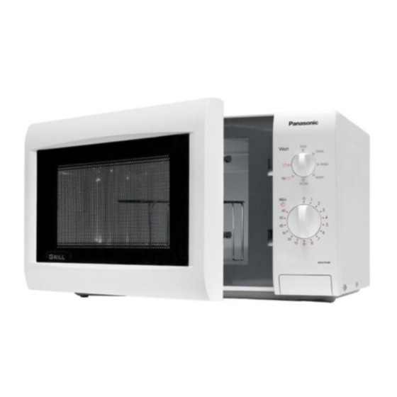
OPERATING INSTRUCTIONS FEATURES Oven Front Plate Window Door Screen Door Seal Control Panel Safety Door Lock System Turntable Roller Rest Grill rack CONTROL PANEL NN-K105WB (UK) NN-K105WB NN-K135MB 1. POWER CONTROL KNOB: Used to select power level for cooking. 2. TIMER KNOB: Used to set the cooking time. -
Page 8: Operating Sequence
OPERATING SEQUENCE MICROWAVE COOKING GRILL COOKING 1. Open the oven door, place the food on the turntable in 1. Open the oven door, place the food on the rack in the oven, and close the oven door. the oven, and close the oven door. 2. -
Page 9: Circuit Description
CIRCUIT DESCRIPTION WHEN THE DOOR IS OPENED DURING • As the door is closed, the contact of MONITOR SWITCH opens. This switch creates the short circuit to COOKING blow fuse during operation under abnormal condition. (ie, should the contacts of primary and secondary •... -
Page 10: Service Information
SERVICE INFORMATION TOOLS AND MEASURING INSTRUMENTS NECESSARY TOOLS NECESSARY MEASURING INSTRUMENTS Tools normally used for TV servicing are sufficient. • TESTER (VOLTS-DC, AC, Ohmmeter) • Microwave survey meter Standard tools are listed below. - Holaday HI-1500 • Diagonal pliers HI-1501 •... - Page 11 MEASUREMENT WITH OUTER CASE NOTES WHEN MEASURING REMOVED • Do not exceed meter full scale deflection. • The test probe must be removed no faster than • When you replace the magnetron, measure for 1 inch/sec(2.5 cm/sec) along the shaded area, microwave energy leakage before the outer case is otherwise a false reading may result.
-
Page 12: Measurement Of Microwave Power Output
MEASUREMENT OF MICROWAVE POWER OUTPUT • Microwave power output measurement is made with • The microwave power output P in watts is calculated the microwave oven supplied at its rated voltage and from the following formula : operated at its maximum microwave power setting with 4187 x (∆T) + 0.55 X (T ) X M a load of (1000±5) g of potable water. - Page 13 D. DOOR GROSS ASSEMBLY REMOVAL E. HIGH VOLTAGE TRANSFORMER REMOVAL 1) Open the door. 2) Remove the choke cover cap very carefully with a 1) Discharge the high voltage capacitor. flat-blade screwdriver. 2) Disconnect the leadwire from magnetron, voltage CAUTION : Be careful not to damage door seal transformer, and capacitor.
- Page 14 H. AIR DUCT ASSEMBLY REMOVAL J. REMOVING THE TURNTABLE MOTOR 1) Disconnect the leadwire from lamp,A.C Relay and 1) Remove the turntable. monitor resistor. 2) Remove the turntable shaft VERY CAREFULLY. 2) Remove the mounting screw to the magnetron. 3) Lay the unit down on its back. 4) Remove the turntable motor cover.
- Page 15 K. TIMER MOTOR REMOVAL L. INTERLOCK SYSTEM 1) Remove the control panel assembly from the 1) INTERLOCK MECHANISM cavity. The door lock mechanism is a device which has 2) Remove screws which hold the timer motor to the been specially designed to eliminate completely control panel.
- Page 16 MEASUREMENT OF MICROWAVE POWER OUTPUT WARNING : FOR CONTINUED PROTECTION AGAINST EXCESSIVE RADIATION EMISSION, REPLACE ONLY WITH IDENTICAL REPLACEMENT PARTS. ALL THESE SWITCHES MUST BE REPLACED AT THE SAME TIME. TYPE NO.SZM-V 16-FA-63 OR VP-533A-OF FOR PRIMARY SWITCH TYPE NO.SZM-V 16-FA-62 OR VP-532A-OF FOR MONITOR SWITCH TYPE NO.SZM-V 16-FA-63 OR VP-533A-OF FOR SECONDARY SWITCH A.
-
Page 17: Component Test Procedure
COMPONENT TEST PROCEDURE CAUTIONS 1. DISCONNECT THE POWER SUPPLY CORD FROM THE OUTLET WHENEVER REMOVING THE OUTER CASE FROM THE UNIT. PROCEED WITH THE TEST ONLY AFTER DISCHARGING THE HIGH VOLTAGE CAPACITOR AND REMOVING THE WIRE LEADS FROM THE PRIMARY WINDING OF THE HIGH VOLTAGE TRANSFORMER. - Page 18 COMPONENTS TEST PROCEDURE RESULTS Antenna Gasket Chassis Filament Terminals NOTE: When testing the magnetron, be sure to install the magnetron gasket in the correct position and be sure that the gasket is in good condition. HIGH VOLTAGE Measure the resistance. Normal: Momentarily indicates CAPACITOR (Ohm-meter scale: Rx1000)
- Page 19 COMPONENTS TEST PROCEDURE RESULTS MAIN FUSE Check for continuity of the fuse with an Normal Abnormal multi-meter. NOTE: If the fuse is blown, check the primary, the secondary, and the monitor switches, H.V.D. and H.V.C. before replacing the fuse. If the fuse is blown by improper switch operation replace the defective switch and the fuse at the same time.
- Page 20 COMPONENTS TEST PROCEDURE RESULTS TIMER MOTOR Turn on Turn Off (Wire leads removed) (2-3) Approx. 25 K (2-M) Note: A is ON, OFF switch B is power supply terminal of the timer motor C is defrost switch (1-2) Measure the resistance. FAN MOTOR Normal: (Wire leads removed)
-
Page 21: Trouble Shooting
TROUBLE SHOOTING WHEN YOU GET A COMPLAINT FROM YOUR CUSTOMER, EVALUATE THE COMPLAINT CAREFULLY. IF THE FOLLOWING SYMPTOMS APPLY, PLEASE INSTRUCT THE CUSTOMER IN THE PROPER USE OF THE MICROWAVE OVEN. THIS CAN ELIMINATE AN UNNECESSARY SERVICE CALL. CAUTIONS 1. Check grounding before checking for trouble. 2. - Page 22 (TROUBLE 1) Oven lamp does not turn on when the timer knob is pushed with door closed. CONDITION CHECK RESULT CAUSE REMEDY Malfunction of the Replace fuse, Check continuity 1. Fuse blows. Continuity. monitor switch. primary, monitor of monitor and secondary switch (with switches.
- Page 23 CONDITION CHECK RESULT CAUSE REMEDY No continuity. Check the Malfunction of the replace. continuity of the timer switch. timer switch contacts. Check the continuity of the No continuity. Faulty thermostat. replace. thermostat. (TROUBLE 3) Output power is low. CONDITION CHECK RESULT CAUSE REMEDY...
- Page 24 (TROUBLE 5) Oven does not cook at all even though turntable rotates. CONDITION CHECK RESULT CAUSE REMEDY No microwave Replace the power Malfunction of the No continuity. Check the oscillation. control switch. power control power control switch. switch(cooking state). Continuity. Check the Abnormal or burn Defective monitor...
- Page 25 EXPLODED VIEW & REPLACEMENT PARTS LISTS Please note: Due to improvements made during the production life of these models the parts lists relevant to your model should be identified by serial number. Please use the following table to define which parts list is relevant to your model: For serial numbers within the ranges shown below , please refer to Section A for spare parts.