Table of Contents
Advertisement
Quick Links
IMPORTANT
READ CAREFULLY BEFORE USE
KEEP SAFE TO CONSULT AT A LATER DATE
Translation of original operating instructions for
BULLS Pedelecs with BOSCH KIOX300 Display and
LCD Remote on-board computer
C R O S S L I T E E V O 1 , C R OS S L I T E E V O 2 , C R O S S M O V E R E V O 3 , C RO S S RI D E R E V O 2 ,
I C O N I C E V O T R 1 , I C O N I C E V O T R 2
22- 15- 106 9...2 2-1 5-1 077, 2 2-15-1 087 ...22-15 -10 89, 22-15 -40 07...22- 15- 400 9
MY22 B0a - 62 _1.0 _ 16.09.20 21
Advertisement
Table of Contents

Related Manuals for Bosch BULLS KIOX300


Summary of Contents for Bosch BULLS KIOX300
- Page 1 KEEP SAFE TO CONSULT AT A LATER DATE Translation of original operating instructions for BULLS Pedelecs with BOSCH KIOX300 Display and LCD Remote on-board computer C R O S S L I T E E V O 1 , C R OS S L I T E E V O 2 , C R O S S M O V E R E V O 3 , C RO S S RI D E R E V O 2 , I C O N I C E V O T R 1 , I C O N I C E V O T R 2 22- 15- 106 9…2 2-1 5-1 077, 2 2-15-1 087 …22-15 -10 89, 22-15 -40 07…22- 15- 400 9...
-
Page 2: Table Of Contents
Contents Contents About these operating instructions Manufacturer Laws, standards and directives Language For your information 1.4.1 Warnings 1.4.2 Markups Type number and model Frame number Identifying the operating instructions Aim of the operating instructions Safety Residual risks 2.1.1 Risk of fire and explosion 2.1.1.1 Rechargeable battery 2.1.1.2... -
Page 3: Cross Lite Evo
SHIMANO SW-E7000 derailleur gears 3.4.6 Hand brake Technical data 3.5.1 Pedelec 3.5.2 Emissions 3.5.3 Bicycle lighting 3.5.4 Display mount 3.5.5 LED Remote on-board computer 3.5.6 BOSCH Kiox300 display 3.5.7 BOSCH Performance Line CX motor 3.5.8 BOSCH PowerTube 750 battery MY22B0a - 62_1.0_15.09.2021... - Page 4 Contents 3.5.9 Tightening torques Transporting and storing Weight and dimensions for transportation Designated handles, lifting points Transportation 4.3.1 Using the transport securing system 4.3.2 Transporting the pedelec 4.3.3 Shipping a pedelec 4.3.4 Transporting the battery 4.3.5 Shipping the battery Storing 4.4.1 Break in operation 4.4.1.1...
- Page 5 Contents 6.5.5.3 Adjusting the handlebars 6.5.6 Stem 6.5.6.1 Adjusting the handlebar height with quick release 6.5.6.2 Setting the quill stem 6.5.6.3 Adjusting the Ahead stem 6.5.6.4 Adjusting the angle-adjustable stem 6.5.7 Ergonomic handles 6.5.7.1 Checking handlebar stability 6.5.8 Tyres 6.5.9 Brake 6.5.9.1 Brake handle position...
- Page 6 Contents Before each ride Straightening the quickly adjustable stem 6.10 Using the pannier rack 6.11 Raising the kickstand 6.12 Using the saddle 6.12.1 Using the leather saddle 6.13 Using the pedals 6.14 Using the multifunctional handlebars or bar ends 6.14.1 Using leather handles 6.15 Using the bell...
- Page 7 Contents 7.3.3 Motor 7.3.4 Frame, fork, pannier rack, guards and kickstand 7.3.5 Stem 7.3.6 Handlebars 7.3.7 Handles 7.3.7.1 Leather handles 7.3.8 Seat post 7.3.9 Saddle 7.3.9.1 Leather saddle 7.3.10 Tyres 7.3.11 Spokes and spoke nipples 7.3.12 7.3.13 Switching elements 7.3.13.1 Shifter 7.3.14 Cassette, chain wheels and front derailleur...
- Page 8 Contents 7.5.2.1 Checking the hand brake 7.5.2.2 Checking the hydraulic system 7.5.2.3 Checking the Bowden cables 7.5.2.4 Checking the disc brake 7.5.2.5 Checking the back-pedal brake 7.5.2.6 Checking the rim brake 7.5.3 Checking the lighting 7.5.4 Checking the stem 7.5.5 Check the handlebars 7.5.6 Checking the saddle...
- Page 9 Contents 9.1.6 Other errors 9.1.7 Suntour suspension fork 9.1.7.1 Rebound too fast 9.1.7.2 Rebounding too slowly 9.1.7.3 Suspension too soft on inclines 9.1.7.4 Excessively hard damping on bumps 9.1.8 Rear frame damper 9.1.8.1 Rebound too fast 9.1.8.2 Rebounding too slowly 9.1.8.3 Suspension too soft on inclines 9.1.8.4...
- Page 10 About these operating instructions Thank you for your trust! Copyright BULLS pedelecs are premium quality vehicles. © ZEG Zweirad-Einkaufs-Genossenschaft eG You have made an excellent choice. Your specialist dealer will provide you with guidance Distribution or reproduction of these operating and instruction and assemble your product.
-
Page 11: About These Operating Instructions
About these operating instructions About these operating instructions Manufacturer 1.4.1 Warnings Warnings indicate hazardous situations and ZEG Zweirad-Einkaufs-Genossenschaft eG actions. You will find three warnings in the Longericher Strasse 2 operating instructions: 50739 Köln, Germany Tel.: +49 221 17959 0 WARNING Fax: +49 221 1795931... -
Page 12: Type Number And Model
About these operating instructions Frame number ype number and model Each frame has an individual frame number These operating instructions are an integral part of stamped on it (see Figure 2). The frame number pedelecs with the type numbers: can be used to associate the pedelec with the Type no. -
Page 13: Aim Of The Operating Instructions
About these operating instructions Aim of the operating instructions These operating instructions are not a substitute for personal instruction by the specialist dealer supplying the bike. These operating instructions Section are an integral part of the pedelec. Therefore, if it is re-sold at a later time, they must be handed over to the subsequent owner. -
Page 14: Safety
Safety Safety Residual risks 2.1.1 Risk of fire and explosion 2.1.1.1 Rechargeable battery Chargers with excessive voltage damage batteries. This may cause a fire or an explosion. The safety electronics may fail if the batteries are Only use approved batteries to charge. damaged or faulty. -
Page 15: Electric Shock
Safety 2.1.2 Electric shock 2.1.2.1 Damage 2.1.3.2 Incorrect tightening torque If a screw is fastened too tightly, it may break. If a Damaged chargers, cables and plug connectors screw is not fastened enough, it may loosen. This increase the risk of electric shock. will cause a crash with injuries. -
Page 16: Malfunctions Due To Bluetooth
3, data is transferred to BOSCH eBike Systems (Robert Bosch GmbH) on the use of the Bosch drive unit, including its energy consumption and temperature, to help improve the product. You will find more information on the Bosch eBike website: www.bosch-ebike.com. MY22B0a - 62_1.0_15.09.2021... -
Page 17: Toxic Substances
Safety Toxic substances Personal protective equipment 2.2.1 Brake fluid Wear a suitable helmet. The helmet must have a reflective strip or a light in a clearly visible Brake fluid may leak out after an accident or due colour. to material fatigue. Brake fluid can be fatal if ... -
Page 18: Safety Markings And Safety Instructions
Safety Safety markings and safety What to do in an emergency instructions 2.8.1 Dangerous situation in road traffic The pedelec and battery nameplates contain these safety markings and safety instructions: If you encounter any hazards or dangers in road traffic, apply the brake on the pedelec until it comes to a halt. -
Page 19: Battery Vapours Emitted
Safety 2.8.4 Battery fire After swallowing Rinse out mouth with water. Never induce The safety electronics may fail if the battery is vomiting. Risk of aspiration. damaged or faulty. The residual voltage can cause a short circuit. The battery may self-ignite ... -
Page 20: Description
Description Description Proper use All check lists and instructions for actions in these The rechargeable batteries are designed to operating instructions must be met. Approved supply power to the pedelec motor only. Never accessories can be installed by specialist staff. use the batteries for other purposes. -
Page 21: Improper Use
Description 3.1.1 Improper use Failure to adhere to the proper use poses a risk of • lending the pedelec to untrained riders • carrying other people personal injury and material damage. It is • riding with excessive baggage prohibited to use the pedelec in the following •... -
Page 22: Permitted Total Weight (Ptw)
About these operating instructions 3.1.2 Permitted total weight (PTW) The pedelec may only be loaded to its maximum permitted total weight (PTW). The maximum permitted total weight is • the weight of the fully assembled pedelec • plus body weight •... -
Page 23: Environmental Requirements
Description 3.1.3 Environmental requirements You can be ride the pedelec within a temperature Temperatures under -10 °C and over +60 °C must range between -5 °C and +40 °C. The electric be avoided as a general rule. Never put the drive system is limited in its performance outside battery in a car in summer or store it in direct this temperature range. - Page 24 Description The pedelec is unsuitable for the following areas of use: Child's City and bicycles/ Area of use trekking Mountain bikes Racing bicycle Cargo bike Folding bicycle bicycles for bicycles young adults Never drive off- Never drive off- Never drive off- Never drive off- Never drive off- road or perform...
-
Page 25: Nameplate
Description Nameplate The nameplate is situated on the frame. The Figure 2. The nameplate contains thirteen pieces precise position of the nameplate is shown in of information. ZEG Zweirad-Einkaufs- Genossenschaft eG Longericher Str. 2 50739 Köln, Germany Typ: 22-17-1017 EPAC nach EN 15194 0,25 kW / 25 km/h... -
Page 26: Components
Description Components 3.3.1 Overview 23 24 Figure 2: Pedelec from right; BULLS Sonic EVO AM-I Carbon used as example Front wheel Seat post Rear wheel hub Front wheel hub Saddle Chain Fork Pannier rack Chain guard Front wheel mudguard Rear light Frame number Front light Reflector... -
Page 27: Chassis
Description 3.3.2 Chassis The chassis comprises two components: • Frame and • steering system. 3.3.2.1 Frame The frame absorbs all forces which act on the pedelec from body weight, pedalling and the ground. The frame also acts as a carrier for most components. - Page 28 Description 3.3.2.5 Handlebars 3.3.2.6 Fork The stem and handlebars are attached to the top The pedelec is steered using the handlebars. The end of the fork steerer. The axle is fastened to the handlebars are used to support the upper body fork ends.
-
Page 29: Suspension
Description 3.3.3 Suspension Both forks and suspension forks are fitted in this model series. 3.3.3.1 Rigid fork Rigid forks do not feature suspension. They transfer the used muscle and motor power to the road to optimum effect. Pedelecs with rigid forks consume less energy on steep roads and have a greater range than pedelecs with suspension. - Page 30 Description Negative deflection (sag) The negative deflection (sag) is the percentage of optimally adjusted. The wheel stays in contact total deflection that is compressed by body with the ground when passing over bumps (blue weight, including equipment (such as a line).
- Page 31 Description Rebound damping Only applies to pedelecs with this equipment Rebound damping defines the speed at which the Rebound damping needs to be increased to suspension rebounds after being loaded. achieve an optimal setting if the air pressure or Rebound damping controls the suspension fork spring stiffness are increased.
- Page 32 Description Steel suspension fork structure Air suspension fork structure The stem and the handlebars are fastened to the Depending on the model, the air suspension fork has either fork steerer. The wheel is fastened to the axle. • an air suspension assembly group (orange) and/ •...
-
Page 33: Rear Frame Damper
Overview 3.3.3.3 Rear frame damper A rear frame damper is primarily fitted to mountain The rear frame damper rebounds at a controlled bikes and helps to protect the pedelec and rider speed if it is optimally adjusted. The rear wheel against impacts and vibrations caused by uneven does not bounce off rough surfaces or the ground;... - Page 34 Overview When optimally adjusted, the rear frame damper The saddle rises slightly when absorbing a bump deflects quickly and unhindered when the bike hits (green line). bumps and absorbs a bump. Traction is retained (blue line). Figure 17: Optimum rear frame damper ride performance over bumps MY22B0a - 62_1.0_15.09.2021...
-
Page 35: Suntour Rear Frame Damper
Description 3.3.3.4 Suntour rear frame damper The rear frame damper features air suspension, a compression damper and a rebound damper. Figure 18: Example showing Suntour rear frame damper Air chamber Rebound lever (rebound setting) Air valve Lockout lever Total damper length Negative deflection in the rear frame damper Damper unit O-ring... - Page 36 Description Rebound damping for rear frame damper Only applies to pedelecs with this equipment The rear frame damper rebounds at a controlled position when the next bump is absorbed. The speed if it is optimally adjusted. The rear wheel suspension motion is predictable and controlled. does not bounce off rough surfaces or the ground;...
-
Page 37: Wheel
Description 3.3.4 Wheel If a tyre with a deep tread is used on asphalt, this may make an unpleasant noise when the brakes are used In such a case, the specialist dealer needs to replace the tyre with a new one with a shallow tread. -
Page 38: Spoke
Description The pedelec has either: Schrader valve • a conventional valve The Schrader valve can be pumped at filling • a Presta valve or stations. Older and easy bicycle pumps are • a Schrader valve. unsuitable for filling tyres via a Schrader valve. Dunlop valve The Dunlop valve, also known as a conventional valve, is the valve in most widespread use. -
Page 39: Braking System
Description 3.3.5 Braking system A pedelec's brake system is primarily operated 3.3.5.2 Hydraulic brake using the brake lever on the handlebars. The brake fluid is in a closed hose system. If the brake lever is pulled, the brake fluid transfers •... -
Page 40: Disc Brake
Description 3.3.5.3 Disc brake Figure 28: Brake system with disc brake – example Brake disc Brake calliper with brake linings Handlebars with brake lever Front wheel brake disc Rear wheel brake disc On a pedelec with a disc brake, the brake disc is screwed permanently to the wheel hub. -
Page 41: Seat Post
Description 3.3.6 Seat post Seat posts are not designed to fasten the saddle Patent saddle posts are fastened into the seat but also to adjust exactly to the optimum sitting tube with either a quick release or a screwable position. The seat post can: clamp. -
Page 42: Mechanical Drive System
Description 3.3.7 Mechanical drive system The pedelec is driven by muscle power, just like a 3.3.7.1 Chain drive layout bicycle. The force which is applied by pedalling in the direction of travel drives the front chain wheel. The chain or belt transmits the force onto the rear chain wheel and then onto the rear wheel. -
Page 43: Electric Drive System
3.3.8.2 Rechargeable battery BOSCH batteries are lithium ion batteries which are developed and manufactured to the latest technical standards. Each battery cell is protected by a steel cup and encased in a plastic battery housing. -
Page 44: Charger
Each battery has its own lock. 3.3.8.3 Charger Each pedelec is supplied with a charger. The following BOSCH charger may be used: • the 4 A Charger BPC3400. PowerTube 750 Observe the operating instructions in the Figure 35: Overview of integrated battery Section 11.4 Documents. -
Page 45: On-Board Computer
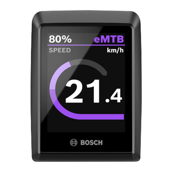
Figure 38: BOSCH Kiox300 display Figure 37: BOSCH LED Remote control panel The display shows the main drive system functions and the ride data. The eBike Flow app can be accessed via Bluetooth®. -
Page 46: Description Of Controls And Screens
Description Description of controls and screens 3.4.1 Handlebars Figure 39: Detailed view of handlebars with BOSCH Kiox300, example 1, 6 Handle LED Remote control panel Rear wheel hand brake (behind handlebars) Air valve cap Bell Sag setting wheel Kiox300 display... -
Page 47: Control Panel
3.4.2 Control panel The control panel on the handlebars is the on-board computer. It controls the system and all indicators on the display screen using six buttons. Figure 40: Overview of BOSCH LED Remote control panel Symbol Designation Symbol Designation >... -
Page 48: System Message
Description 1. Selected level of assistance indicator 3. Battery level indicator (control panel) The higher the selected level of assistance, the The battery level indicator (control panel) shows more the drive system assists with pedalling. the battery charge level. You can also see the battery charge level on the LEDs on the battery eMTB mode is available for Performance Line CX itself. -
Page 49: Creating A User Account
The lock function does not consist of theft Bosch eBike Flow smartphone app as soon as the detection; it is more a supplement to a mechanical app is connected to the on-board computer. -
Page 50: Display
In eMTB mode, the assistance factor and the torque are dynamically adjusted depending on the pedalling force applied to the pedals. Figure 41: BOSCH Kiox300 display Level of assistance The following pages are on the display screen: O FF When the drive system is switched on, the motor assistance is switched off. -
Page 51: Status Screen
Description 5. Title screen 3 . 4 . 3 . 3 S e t t i n g s The title screen indicates the page name and the All system and service-relevant values can be displayed function. read and changed in the settings. The settings menu structure is customised and may change 6. -
Page 52: Battery Level Indicator (Battery)
Description 3.4.4 Battery level indicator (battery) Each battery has its own level indicator: Figure 43: Position of battery level indicator (1) The five green LEDs on the battery level indicator battery show the charge level when the battery is switched on. Each LED represents about 20% battery capacity. -
Page 53: Gear Shift
Description 3.4.5 Gear shift 3.4.5.1 SHIMANO SW-E7000 derailleur gears Only applies to vehicles with this equipment The gear shift unit is on the left of the handlebars. The gear shift unit features 2 buttons. Figure 44: SHIMANO SW-E7000 gear shift Up button (gear shift) Down button (gear shift) MY22B0a - 62_1.0_15.09.2021... -
Page 54: Hand Brake
Description 3.4.6 Hand brake There is a hand brake on the left and right of the handlebars. Figure 45: Front wheel (2) and rear (1) brake levers – Shimano brake used as an example • The left-hand brake controls the front wheel brake. -
Page 55: Technical Data
Transmitting capacity 1 mW Highest effective value of < 0.5 m/s² Table 21: Technical data for BOSCH LED Remote on- weighted acceleration for the board computer, BRC3600 entire body *Not included in the standard scope of delivery Table 18: Emissions from the pedelec* 3.5.6... -
Page 56: Bosch Powertube 750 Battery
750 Wh Weight 4.4 kg Protection class IP54 Operating temperature -5… +40 °C Storage temperature +10… +40 °C Permitted charging temperature 0… 40 °C range Table 24: Technical data for BOSCH PowerTube 750, BBP3770 horizontal, BBP3771 vertical MY22B0a - 62_1.0_15.09.2021... -
Page 57: Tightening Torques
Description 3.5.9 Tightening torques Model Tightening torque Screw On-board computer SC-E5003 Attachment screw 0.8 Nm 3 mm hex bit Shifter SHIMANO DEORE SL-M4100 Attachment screw 3 Nm 4 mm hex bit SHIMANO DEORE SL-M5100 Attachment screw 3 Nm 4 mm hex bit SHIMANO DEORE SL-M6100 Attachment screw 3 Nm... - Page 58 Description eightpins H01 Seat post axle 8 Nm 6 mm hex bit Slipper clutch 18 Nm 3 mm hex bit Valve cap 0.5 Nm 5 mm hex bit Postpin axle 8 Nm 5 mm hex bit Rear clamping screw (saddle) 8 Nm 3 mm hex bit M5 attachment screw for outer sleeve...
-
Page 59: Transporting And Storing
About these operating instructions Transporting and storing Weight and dimensions for transportation Weight and dimensions during transportation. 41 cm # 44 cm # 22-15-1088 48 cm # 54 cm # 44 cm # 48 cm # 22-15-1089 45 cm # 54 cm # 50 cm # 41 cm #... -
Page 60: Transportation
Transportation and storage Transportation 4.3.2 Transporting the pedelec Bicycle rack systems which use the handlebars or frame to hold the pedelec in an upside-down CAUTION position exert inadmissible forces on its components during transportation. This can cause Crash caused by unintentional activation the supporting parts to break. -
Page 61: Storing
Transportation and storage Storing Store the pedelec, on-board computer, battery If the pedelec is removed from service for and charger in a clean, dry place where they longer than four weeks, you need to prepare it are protected from sunlight. for a break in operation. -
Page 62: Assembly 5.1 Unpacking
Assembly Assembly Scope of delivery WARNING 1 pre-assembled pedelec 1 front wheel Risk of eye injury Problems may arise if components are set 2 pedals incorrectly. They may cause serious injuries to 2 quick releases (optional) the face. -
Page 63: Commissioning
Assembly Commissioning Only trained specialist staff may perform initial commissioning since initial commissioning of the pedelec requires special tools and specialist knowledge. Experience has shown that a pedelec which has not yet been sold is automatically handed to customers as soon as it appears ready to ride. ... -
Page 64: Securing The Powertube Bs3 Battery Mount
5.3.1.1 Securing the PowerTube BS3 battery mount Only applies to pedelecs with this equipment The BOSCH PowerTube BS3 battery mount must be secured by clamping a clip on its rear. 1 Use a TORX® T25 wrench to undo the screws in the battery mount. -
Page 65: Preparing The Wheel
Assembly 5.3.2 Preparing the wheel There is an arrow on the sides of the tyres with the inscription ROTATION to show the direction of rotation. The inscription says DRIVE on older tyres. The rotation direction arrow indicates the recommended direction of rotation. On road tyres, the direction of rotation is mainly for optical reasons. -
Page 66: Installing The Wheel In The Suntour Fork
Assembly 5.3.3 Installing the wheel in the SUNTOUR fork Only applies to Suntour forks with this equipment 5.3.3.1 Screw-on axle (12AH2 and 15AH2) Only applies to Suntour forks with this equipment 4 Insert the securing screw on the non-drive side. ... -
Page 67: Mm Cross Axle
Assembly 5.3.3.2 20 mm cross axle Only applies to Suntour forks with this equipment 2 Tighten the cross axle with the red handle. CAUTION Crash caused by loose quick release axle A faulty or incorrectly installed cross axle may become caught in the brake disc and block the wheel. - Page 68 Assembly 5 Check the position and clamping force of the quick release lever. The quick release lever must be flush with the shock absorber. Figure 60: Perfect position for the clamping lever 6 Use 4 mm hexagon socket spanner to adjust the clamping lever clamping force if required.
-
Page 69: Q-Loc Quick Release
Assembly 5.3.3.3 Q-LOC quick release Only applies to Suntour forks with this equipment 1 Push in the quick release until you can hear a click. Make sure that the flange is extended. CAUTION Crash caused by unfastened quick release A faulty or incorrectly installed quick release may become caught in the brake disc and block the wheel. -
Page 70: Fitting The Pedals
Assembly 5.3.4 Fitting the pedals The pedals have two different threads to ensure 3 Turn the pedal marked R anti-clockwise by they don’t come loose while the rider is pedalling. hand into the crank arm on the right as seen when facing the direction of travel. -
Page 71: Preparing The Limotec Seat Post
Assembly 5.3.5 Preparing the LIMOTEC seat post Only applies to pedelecs with this equipment 1 Use the seat height formula to calculate the optimum seat post height for the length of rider's leg: Seat height (SH) = inner leg length (I) × 0.9 2 Lower the seat post further into the seat tube 3 The seat post Bowden cable must be tightened in the frame up to the remote control to the... -
Page 72: Checking The Stem And Handlebars
Assembly 5.3.6 Checking the stem and handlebars 5.3.6.1 Checking the connections 5.3.6.3 Checking the headset backlash 1 Stand in front of the pedelec. Clamp the front 1 Place the fingers of one hand on the upper wheel between your legs. Grasp the handlebar headset cup. -
Page 73: Operation
Operation Operation Risks and hazards WARNING WARNING Injuries and death caused by distraction Injuries and fatalities caused by blind spots A lack of concentration while riding increases the Other road users, trucks, cars and pedestrians risk of an accident. This may cause a crash with often underestimate the speed of pedelecs. - Page 74 Operation CAUTION CAUTION Crash caused by material fatigue Crash caused by soiling Intensive use can cause material fatigue. A Heavy soiling can impair pedelec functions, such component may suddenly fail in case of material as braking. This may cause a crash with injuries. fatigue.
-
Page 75: Tips For A Greater Range
Operation Tips for a greater range The pedelec's range depends on many Gear shift influencing factors. A single battery charge may Use a low gear and a low level of assistance on only last fewer than 20 kilometres but much more hills and when setting off. -
Page 76: Error Message
Operation Error message 6.3.1 On-board computer The control panel indicates whether a critical or 6.3.2 Rechargeable battery less critical error has arisen in the drive system. The battery is protected against deep discharge, The error messages generated by the drive overcharging, overheating and short circuits by system can be read in the eBike Flow app and by Electronic Cell Protection (ECP). -
Page 77: Instruction And Customer Service
Operation Instruction and customer service The supplying specialist dealer will provide 6.5.1 Preparing customer service. Contact details can be found on The following tools are required to adjust the the pedelec pass for these operating instructions. pedelec: The specialist dealer will explain all the pedelec functions to the new owner in person, this being when the specialist dealer hands over the pedelec Tape measure... -
Page 78: Pedelec Adjustment Procedure
Operation 6.5.2 Pedelec adjustment procedure Observe the correct order for adjustment. For pedelecs with components only Sequence Adjustment Section Saddle • Straighten saddle 6.5.4.1 • Adjust saddle height 6.5.4.2 • Adjust saddle position 6.5.4.4 • Adjust saddle tilt 6.5.4.5 Handlebars 6.5.5 Stem... -
Page 79: Determining The Sitting Position
Operation 6.5.3 Determining the sitting position The starting point for a comfortable posture is the correct position of the pelvis. If the pelvis is in the wrong position, it can cause different types of pain, e.g. in the shoulder or back. Figure 69: The pelvis is in the right position (green) or incorrect position (red) The pelvis is in the right position if the spine forms... - Page 80 Operation Position on roadster Position on city bike Position on trekking Position on sports bike bike Upright, almost vertical Slightly inclined upper Considerably inclined Sharply inclined upper posture, body, upper body, body, back at an angle of back at an angle of 60°– back at an angle of 30°–...
-
Page 81: Adjusting The Saddle
Operation 6.5.4 Adjusting the saddle 6.5.4.1 Straightening the saddle 6.5.4.2 Adjusting the saddle height To adjust the saddle height safely, either: Position saddle in direction of travel. In doing • Push the pedelec near to a wall so that the rider so, align the tip of the saddle with the top tube. -
Page 82: Setting The Saddle Height With The Remote Control
Operation 5 Open the quick release on the seat post to 6.5.4.3 Setting the saddle height with the remote control change the seat height (1). To do so, push the clamping lever away from the seat post (3). Use the seat height formula to set the saddle height: Seat height (SH) = inner leg length (I) ×... -
Page 83: Adjusting The Saddle Position
Operation 6.5.4.4 Adjusting the saddle position 3 Unfasten and adjust the designated screw connections, and clamp them with the The saddle can be shifted on the saddle frame. maximum tightening torque for the saddle The right horizontal position ensures an optimal clamping screws. -
Page 84: Handlebars
Operation 6.5.5 Handlebars Check handlebar width and hand position. The narrower the shoulders are, the greater the bend of the handlebars should be (maximum 28°). Choose different handlebars if necessary. Contact specialist dealer. Straight handlebars are advisable for sports bikes (e.g. -
Page 85: Stem
Operation 6.5.6 Stem 6.5.6.1 Adjusting the handlebar height with Adjusting the quick release clamping force quick release Only applies to pedelecs with this equipment CAUTION 1 Open the stem clamping lever. Crash caused by incorrectly set clamping force Applying excessive clamping force damages the quick release. -
Page 86: Setting The Quill Stem
Operation 6.5.6.2 Setting the quill stem 6.5.6.3 Adjusting the Ahead stem Only applies to pedelecs with this equipment Only applies to pedelecs with this equipment In the case of a quill stem, the stem and fork In the case of an Ahead stem, the stem is placed steerer form a permanently interconnected directly on the fork steerer, which protrudes over component, which is clamped in the fork steerer. -
Page 87: Adjusting The Angle-Adjustable Stem
Operation 6.5.6.4 Adjusting the angle-adjustable stem Only applies to pedelecs with this equipment Angle-adjustable stems are available in different lengths for quill and Ahead stems. Figure 84: Different versions of angle-adjustable stems Adjusting the stem angle (c) changes both the distance from the upper body to the handlebars (b) and the handlebar height (a). -
Page 88: Ergonomic Handles
Operation 6.5.7 Ergonomic handles In the case of ergonomically shaped handles, the palm rests on the anatomically shaped handle. A greater contact surface means that the pressure is more evenly distributed. Nerves and vessels are no longer squeezed in the carpal tunnel. Figure 86: Correct (1) and incorrect (2) position of the handle 1 Undo the handle screw. -
Page 89: Tyres
Operation 6.5.8 Tyres It is not possible to offer a general recommended Tyre pressure in bar for body tyre pressure for a particular pedelec or tyre. The weight correct tyre pressure largely depends on the Tyre width about about about weight load on the tyres, mainly determined by 60 kg 80 kg... -
Page 90: Brake
Operation 6.5.9 Brake The brake lever grip distance can be adjusted to 6.5.9.2 Brake handle tilt angle ensure that it can be reached more easily. The The nerves that pass through the carpal tunnel pressure point can also be adjusted to the rider's are connected to the thumb and the index and preferences. -
Page 91: Determining The Grip Distance
Operation 2 Set the brake lever angle as indicated in the table. 20 – 25° > 10 cm 25 – 30° 0 – 10 cm 30 – 35° 0 – 10 cm 35 – 45° > 10 cm Saddle-handlebar height Brake angle difference (mm) >10... -
Page 92: Retracting The Brake Linings
Operation 6.5.9.4 Retracting the brake linings Disc brakes require wearing-in time. The braking force increases over time. The braking force is increased during break-in time. This is also the case when the brake pads or brake discs are replaced. 1 Accelerate pedelec to 25 km/h. 2 Brake pedelec until it comes to a halt. -
Page 93: Tyres
Operation 6.5.10 Tyres It is not possible to offer a general recommended Tyre pressure in bar for body tyre pressure for a particular pedelec or tyre. The weight correct tyre pressure largely depends on the Tyre width about about about weight load on the tyres, mainly determined by 60 kg 80 kg... -
Page 94: Grip Distance On A Shimano St-Ef41 Brake Lever
Operation 6.5.10.1 Grip distance on a SHIMANO ST-EF41 brake lever Only applies to pedelecs with this equipment Turn setting screw anti-clockwise towards The brake lever position can be adjusted to the rider's requirements. Such adjustment does not minus (–). affect the pressure point or the position of the ... -
Page 95: Grip Distance On A Shimano St-Ef41 Brake Lever
Operation 6.5.10.2 Grip distance on a SHIMANO ST-EF41 brake lever Only applies to pedelecs with brakes: BL-M4100 BL-M7100 BL-M8100 BL-MT200 BL-MT201 BL-MT400 BL-MT401 BL-MT402 BL-T6000 GRX ST-RX600 M7100 M8100 RS785 The brake lever position can be adjusted to the rider's requirements. Contact your specialist dealer. -
Page 96: Suspension
Operation 6.5.11 Suspension A pedelec’s fork suspension and rear frame Follow the the correct order for adjustment. damper suspension can be adjusted to the rider's weight in up to six increments, depending on the suspension system. For pedelecs with components only Sequence Adjustment Section... -
Page 97: Adjusting The Suntour Fork Steel Suspension
Operation 6.5.12.1 Adjusting the Suntour fork steel suspension Only applies to pedelecs with this equipment 1 You will find the sag setting wheel (1) beneath the plastic cover on the crown. Remove the plastic cover. Figure 96: Sag setting wheel (1) on the suspension fork crown ... -
Page 98: Adjusting The Suntour Fork Air Suspension
Operation 6.5.12.2 Adjusting the Suntour fork air suspension Only applies to pedelecs with this equipment The air valve is located beneath the air valve 1 Attach a high-pressure damper pump to the air cap on the crown. Twist off the air valve cap. valve. -
Page 99: Adjust The Rear Frame Damper Sag
Operation 6.5.13 Adjust the rear frame damper sag Settings on the chassis change ride performance significantly. The rider needs to get used to the pedelec and break it in to prevent accidents. Greater sag (20%–30%) A greater sag increases sensitivity to bumps, thus producing greater suspension motion. -
Page 100: Adjusting The Suntour Rear Frame Damper
Operation 6.5.13.1 Adjusting the Suntour rear frame damper Only applies to pedelecs with this equipment Every rear frame damper has a specific delivery After setting up the rear wheel damper, check the These levels are starting air pressure ex works. sag to ensure the recommended sag settings are points. -
Page 101: Fork Rebound Damping
Operation 6.5.14 Fork rebound damping Only applies to pedelecs with this equipment Rebound damping in the suspension fork and the Rebound damping needs to be increased to rear frame damper determines the speed at which achieve an optimal setting if the air pressure or the rear frame damper rebounds after being spring stiffness are increased. -
Page 102: Adjusting The Suntour Fork Rebound Damping
Operation 6.5.14.1 Adjusting the Suntour fork rebound damping Only applies to pedelecs with this equipment Figure 99: Example of Suntour rebound screw (1) The fork sag is adjusted. 1 Turn the rebound screw in a clockwise direction to the closed position until it stops. 2 Turn the rebound screw slightly in an anti- clockwise direction. -
Page 103: Adjusting The Rear Frame Damper Rebound Damper
Operation 6.5.15 Adjusting the rear frame damper rebound damper Only applies to pedelecs with this equipment The rear frame damper rebounds at a controlled frame damper rebounds in a controlled way, so speed if it is optimally adjusted. The rear wheel that the rider remains sitting in a horizontal does not bounce off rough surfaces or the ground;... -
Page 104: Adjusting The Suntour Rear Frame Damper
Operation 6.5.15.1 Adjusting the Suntour rear frame damper Only applies to pedelecs with this equipment Figure 101: Suntour rebound adjuster wheel (1) on the rear frame damper The sag in the rear frame damper is adjusted. Turn rebound wheel towards minus. ... -
Page 105: Compression Adjuster On Rear Frame Damper
Operation 6.5.16 Compression adjuster on rear frame damper When optimally adjusted, the rear frame damper deflects quickly and unhindered when the bike hits bumps and absorbs a bump. Traction is retained (blue line). The saddle rises slightly when absorbing a bump (green line). Compression adjuster set to hard Compression adjuster set to soft •... -
Page 106: Adjusting The Suntour Compression Adjuster
Operation 6.5.16.1 Adjusting the Suntour compression adjuster Only applies to pedelecs with this equipment Figure 103: Suntour compression adjuster (1) on the rear frame damper 1 Set the compression adjuster to the middle position. 2 Ride the pedelec over a small obstacle. ... -
Page 107: Lighting
Operation 6.5.17 Lighting Example 1 If the front light is positioned too high, oncoming traffic will be dazzled. This can cause a serious accident with fatalities. Example 2 Positioning the front light correctly can ensure that oncoming traffic is not dazzled and no-one is put at risk. Example 3 If the front light is positioned too low, the space ahead is not illuminated to an optimum extent and the rider's vision is reduced in the dark. - Page 108 Operation 4 Place pedelec 5 m from the wall. 6 Switch on riding light. 5 Stand the pedelec up straight. Hold the handlebars straight with both hands. Do not use the kickstand. Figure 106: Light positioned too high (1), correctly (2) and too low (3) 7 Check the position of the light beam.
-
Page 109: On-Board Computer
The on-board computer is now connected to the smartphone. Registering on a PC The drive system is switched on. 1 Create the user account on the BOSCH The pedelec is stationary. website. A new software update is downloaded 2 Enter all the details required for registration. -
Page 110: Inserting The Display
About these operating instructions Once the lock function is switched on, the pedelec 6.5.18.7 Securing the on-board computer (optional) can only be put into use if: It is possible to secure the on-board computer so • the configured smartphone is switched on, that it cannot be removed. -
Page 111: Adjust On-Board Computer
(such as the S ET TI N G S menu). Open start screen Press On-Off button Figure 110: Overview of BOSCH LED Remote control The S T A R T S C R E E N is displayed. panel... -
Page 112: Adjust On-Board Computer
About these operating instructions 6.5.18.10Adjust on-board computer The pedelec is stationary. You cannot open and 6.5.18.11Selects the language adjust the settings while riding. 1 Open <System> menu item. The display is inserted and shows the start screen. 2 Open < Language> sub-menu item. 1 Open S T A T U S S C R EE N . -
Page 113: Reset Settings
About these operating instructions 6.5.18.16Reset settings 1 Open <System> menu item. 2 Open <Settings reset> sub-menu item. 3 Follow the instructions on the on-board computer. All settings are reset to the factory settings. All user data has been cleared. MY22B0a - 62_1.0_15.09.2021... -
Page 114: Accessories
Operation Accessories We recommend a parking stand into which either the front wheel or rear wheel can be inserted CAUTION securely for pedelecs which do not have a kickstand. The following accessories are Risk of crushing due to exposed springs recommended: The child may crush his/her fingers on exposed Description... -
Page 115: Trailer
Operation 6.6.2 Trailer 6.6.2.1 Approval for trailer with Enviolo hub Only applies to pedelecs with this equipment CAUTION Only compatible bicycle trailers are approved for ENVIOLO hub gears. Crash caused by brake failure KETTLER The braking distance may be longer if the trailer is carrying excessive load. -
Page 116: Approval For Trailer With Rohloff Hub
Operation 6.6.4 Tubeless and airless tyres 6.6.2.2 Approval for trailer with ROHLOFF hub Only applies to pedelecs with this equipment Bicycle riding without tubes reduces the risk of tyre punctures or even avoids them completely. ROHLOFF Speedhub 500/14 The specialist dealer will advise on choosing a As a basic rule, it is permitted to use a trailer suitable tyre system for the pedelec. -
Page 117: Personal Protective Equipment And Accessories For Road Safety
Operation Personal protective equipment and accessories for road safety Seeing and being seen is crucial in road traffic. 7 The two separate brakes on the pedelec must The following requirements must be met for riding work at all times. a road-safe vehicle on public roads. 8 The clear sounding bell must be fitted and must work. -
Page 118: Straightening The Quickly Adjustable Stem
Operation Straightening the quickly 6.10 Using the pannier rack adjustable stem CAUTION Only applies to pedelecs with this equipment 1 Open stem clamping lever. Crash caused by loaded pannier rack The pedelec is handled differently with a loaded pannier rack, in particular when the rider needs to steer and brake. -
Page 119: Raising The Kickstand
Operation 6.13 Using the pedals The ball of the foot is placed on the pedal when riding and pedalling. Figure 116: The maximum load bearing (1) capacity is indicated on the pannier rack. Never exceed the maximum permitted total weight when packing the pannier. -
Page 120: Using The Battery
Operation 6.16 Using the battery Switch off the battery and the drive system before 6.16.1.1 Inserting the battery removing or inserting the battery. The key is inserted in the lock. The lock is unlocked. 6.16.1 Removing the battery Figure 119: Inserting the integrated battery Figure 118: Removing the integrated battery 1 Place the battery into the lower mount with the... -
Page 121: Charging The Battery
Operation 6.16.2 Charging the battery 4 Once charging is complete, disconnect the battery from the charger. The battery can remain on the pedelec or can be 5 Disconnect the charger from the mains. removed for charging. Interrupting the charging process does not damage the battery. The battery is fitted with a temperature monitoring system which only allows charging within a temperature range between 0 °C and 40 °C. -
Page 122: Using Pedelec With The Electric Drive System
Press the On-Off button (battery). The battery level indicator (control panel) and the indicator for the selected level of assistance go out. The pedelec is switched off. Figure 120: Position of the On-Off button on the BOSCH LED remote MY22B0a - 62_1.0_15.09.2021... -
Page 123: Using The On-Board Computer
Keep the diagnosis port flap closed at all times to ensure no dust or moisture can penetrate through the port. Figure 121: Overview of BOSCH LED Remote control panel 6.18.2 Charging the control panel battery Symbol... -
Page 124: Using The Riding Light
About these operating instructions 6.18.3 Using the riding light 6.18.5 Using the push assist system The drive system needs to be already switched on to turn on the riding light. CAUTION Injury from pedals or wheels The pedals and the drive wheel turn when the push assist system is used. -
Page 125: Selecting The Level Of Assistance
About these operating instructions 6.18.6 Selecting the level of assistance 1 Press Push assist button for longer than 1 seconds. Hold down the button. The control panel is used to set how much the The battery level indicator goes out and a white electric drive should assist the rider when running light in the direction of travel indicates pedalling. -
Page 126: Brake
Operation 6.19 Brake 6.19.1 Using the brake lever WARNING Crash caused by brake failure Oil or lubricant on the brake disc in a disc brake or on the rim of a rim brake can cause the brake to fail completely. This may cause a crash with serious injuries. -
Page 127: Gear Shift
Operation 6.20 Gear shift The selection of the appropriate gear is a Lever A switches from a smaller pinion to a larger prerequisite for a physically comfortable ride and one. The number of pinions switched depends on making sure that the electric drive system the selected position of lever A. -
Page 128: Parking
Operation 6.21 Parking Check list after each ride Notice Cleaning Heat or direct sunlight can cause the tyre pressure Lights and reflectors section 7.2.5 to increase above the permitted maximum Brake section 7.2.5 pressure. This can destroy the tyres. ... -
Page 129: Screwing In The Quickly Adjustable Stem
Operation 6.21.1 Screwing in the quickly adjustable stem Only applies to pedelecs with this equipment Screw in the All Up stem to save space when 3 Turn handlebars 90° in a clockwise direction. parking. 1 Open stem clamping lever. Figure 129: Example of All Up with open stem clamping lever Figure 131: Example of All Up screwed in 2 Pull handlebars into highest possible position. -
Page 130: Activating The Lock Function
Operation 6.21.2 Activating the lock function Only applies to pedelecs with this equipment Remove the on-board computer used during set-up. The lock function is activated. The drive system now provides no assistance. However, the rider can continue to use the pedelec without assistance. -
Page 131: Cleaning, Servicing And Maintenance
Cleaning, servicing and maintenance Cleaning, servicing and maintenance Clean, service and maintain pedelec as indicated on check list. Complying with these measures is the only way to reduce wear on components, increase the operating hours and guarantee safety. Check list before each ride Check list for weekly tasks Check everything is sufficiently Clean chain... - Page 132 Cleaning, servicing and maintenance Check list for monthly tasks Check list for monthly tasks Cleaning the battery Section 7.3.2 Clean hub Section 7.3.12 Clean control panel Section 7.3.1 Cleaning the frame Section 7.3.4 Clean on-board computer Section 7.3.1 Clean tyres Section 7.3.10...
- Page 133 Cleaning, servicing and maintenance Check list for tasks to do every six months (or every 1,000 Check list for tasks to do every six months (or every 1,000 Check Bowden cables gear Check steering headset Section 8.5.6 Section 7.5.10.2 shift ...
- Page 134 Cleaning, servicing and maintenance CAUTION WARNING Crash and falling caused by unintentional Crash caused by brake failure activation Oil or lubricant on the brake disc in a disc brake There is a risk of injury if the drive system is or on the rim of a rim brake can cause the brake activated unintentionally.
-
Page 135: Before Each Ride
Cleaning and servicing Before each ride Complying with these cleaning instructions is the 7.1.5 Checking the pannier rack only way to reduce wear on components, increase 1 Hold onto pedelec by its frame. Hold onto the operating hours and guarantee safety. pannier rack with the other hand. -
Page 136: Checking The Bell
Cleaning and servicing 7.1.10 Checking the bell 1 Press the bell button downwards. 2 Let button spring back. If you do not hear a clear, distinct ring of the bell, replace bell. Contact specialist dealer. 7.1.11 Checking the handles ... -
Page 137: After Each Ride
Cleaning and servicing After each ride Complying with these cleaning instructions is the 7.2.5 Cleaning the brake only way to reduce wear on components, increase the operating hours and guarantee safety. The following items should be ready for use to ... -
Page 138: Basic Cleaning
Cleaning and servicing Basic cleaning Complying with these basic cleaning instructions 7.3.2 Rechargeable battery is the only way to reduce wear on components, increase the operating hours and guarantee safety. The following are required for basic cleaning: CAUTION Tool Cleaning agent Risk of fire and explosion due to penetration by water The battery is only protected from simple spray... -
Page 139: Frame, Fork, Pannier Rack, Guards And Kickstand
Cleaning and servicing 7.3.4 Frame, fork, pannier rack, guards 7.3.7.1 Leather handles and kickstand Leather is a natural product and has similar properties to human skin. Regular cleaning and care help to prevent leather dehydrating, fading or becoming brittle or stained. 1 Soak the components with dish-washing detergent if the dirt is thick and ingrained. -
Page 140: Leather Saddle
Cleaning and servicing 7.3.9.1 Leather saddle 7.3.12 Hub Leather is a natural product and has similar 1 Put on protective gloves. properties to human skin. Regular cleaning and 2 Remove dirt from hub with a sponge and soapy care help to prevent leather dehydrating, fading or water. -
Page 141: Brake
Cleaning and servicing 7.3.15 Brake 7.3.18 Chain 7.3.15.1 Brake lever Notice Carefully clean the brake levers with a damp, soft cloth. Never use aggressive (acid-based) cleaners, rust removers or degreasers when cleaning 7.3.16 Brake disc the chain. Never use gun oil or rust remover spray. ... -
Page 142: Servicing
Cleaning and servicing Servicing Complying with these servicing instructions is the only way to reduce wear on components, increase the operating hours and guarantee safety. Battery terminal grease Table 46: Required tools and cleaning agents for servicing 7.4.1 Frame Notice Figure 132: Diagram showing wear, operating hours (x) ... -
Page 143: Pannier Rack
Cleaning and servicing 7.4.3 Pannier rack 4 If you have a Speedlifter Twist, also apply oil to the unlocking bolt groove in the Speedlifter body. 5 Apply a little acid-free lubricant grease between the stem quick release lever and the 1 Dry pannier rack with a cloth. -
Page 144: Seat Post
Cleaning and servicing 7.4.9 Seat post 7.4.11 Leather saddle 1 Carefully preserve screw connections with wax spray. In doing so, ensure that no wax is applied to the metal contact surfaces. Standard leather care products keep leather 2 Replace the assembly paste protective layer smooth and resistant, brighten its appearance and on the metal contact surfaces on the seat post improve or replace stain protection. -
Page 145: Gear Shift
Cleaning and servicing 7.4.14 Gear shift 7.4.16 Caring for the chain 7.4.14.1 Rear derailleur articulated shafts and jockey wheels Place newspaper or paper towels underneath to collect chain oil. 1 Lift rear wheel. Treat front and rear derailleur articulated 2 Turn the crank briskly in an anti-clockwise shafts and jockey wheels with Teflon spray. -
Page 146: Caring For The Chain And All-Round Chain Guard
Cleaning and servicing 7.4.18 Caring for the brake 7.4.16.1 Caring for the chain and all-round chain guard 7.4.18.1 Caring for the brake Place newspaper or paper towels underneath to collect chain oil. Notice 1 Lift rear wheel. 2 Turn the crank briskly in an anti-clockwise ... -
Page 147: Maintenance
Cleaning and servicing Maintenance The following tools are required for maintenance: 7.5.1.1 Checking the tyre pressure Notice Gloves If the tyre pressure is too low in the tyre, the tyre does not achieve its load bearing capacity. The Ring spanners 8 mm, 9 mm, 10 mm, 13 mm, 14 mm and 15 mm tyre is not stable and may come off the rim. - Page 148 Cleaning and servicing Dunlop valve 6 Screw the rim nut gently against the rim with the tips of your fingers. Only applies to pedelecs with this equipment Correct tyre pressure if necessary (see The tyre pressure cannot be measured on the Section 6.5.10).
-
Page 149: Checking The Tyres
Cleaning and servicing 7.5.1.2 Checking the tyres The tread is far less important for bicycle tyres 2 Check the side walls for wear. If there are any than it is for car tyres, for example. Consequently, cracks or tears, the tyre must be replaced. tyres can still be used with a worn tread with the exception of tyres on mountain bikes. -
Page 150: Checking The Rims
Cleaning and servicing 7.5.1.3 Checking the rims 7.5.1.5 Checking the nipple well The nipple holes can weaken the tyre bed. WARNING Check to see if cracks are emerging from the nipple holes. Crash caused by a worn rim If there are cracks radiating from the nipple A worn rim can break and block the wheel. -
Page 151: Checking The Brake System
Cleaning and servicing 7.5.2 Checking the brake system 7.5.2.2 Checking the hydraulic system CAUTION 1 Push the brake lever and check whether any brake fluid leaks out of the lines, connections or on the brake linings. Crash caused by brake failure Worn brake discs and brake linings and a lack of ... -
Page 152: Checking The Disc Brake
Cleaning and servicing 7.5.2.4 Checking the disc brake Only applies to pedelecs with this equipment Checking the brake linings Checking the brake discs Check that the brake linings are no less than Put on gloves as the brake disc is very sharp. 1.8 mm wide at any point and there are no less 1 Take hold of brake disc and joggle it gently to than 2.5 mm between the brake lining and... -
Page 153: Checking The Back-Pedal Brake
Cleaning and servicing 7.5.2.5 Checking the back-pedal brake Only applies to pedelecs with this equipment There are sharp corners and edges on the back- pedal brake. Wear gloves. 1 Hold and check counter support to ensure it is firmly attached to rear frame down tube. ... -
Page 154: Checking The Rim Brake
Cleaning and servicing 7.5.2.6 Checking the rim brake Only applies to pedelecs with this equipment Checking the brake linings Checking the rim braking surface for wear We recommend that you also replace the rims The side wall is more prone to wear in rim brakes. at the same time as every second brake lining The wear depends on the stress loads during replacement. -
Page 155: Checking The Lighting
Cleaning and servicing 7.5.3 Checking the lighting 1 Check the cable connections on the front and If the front or rear lights do not come on, take pedelec out of service. Contact specialist rear lights for damage and corrosion and dealer. -
Page 156: Checking The Stem
Cleaning and servicing 7.5.4 Checking the stem 7.5.7 Checking the seat post The stem and quick release system must be 1 Take seat post out of the frame. inspected at regular intervals. The specialist 2 Check seat post for cracks and corrosion. dealer should adjust them if they require 3 Reinsert seat post. -
Page 157: Checking The Derailleur Gears
Cleaning and servicing 7.5.10 Checking the gear shift 7.5.9.1 Checking the derailleur gears The chain is tensioned by the rear derailleur in 1 Check whether all gear shift components are pedelecs with derailleur gears. free of damage. 1 Place the pedelec on stand. 2 Contact your specialist dealer if components are damaged. -
Page 158: Adjusting Gear Shift
Cleaning and servicing 7.5.11 Adjusting gear shift 7.5.12 Bowden-cable-operated gear shift, single-cable 7.5.11.1 ROHLOFF hub Only applies to pedelecs with this equipment Only applies to pedelecs with this equipment Adjust the play on the adjusting sleeves on the 1 Check whether the shift cable tension is set in shifter housing to ensure a smooth gear shift. -
Page 159: Bowden-Cable-Operated Twist Grip, Dual-Cable
Cleaning and servicing 7.5.14 Bowden-cable-operated twist grip, 7.5.15 Checking kickstand stability dual-cable 1 Place the pedelec on a slight elevation of 5 cm. Only applies to pedelecs with this equipment 2 Extend kickstand. For a smooth gear shift, set the adjusting 3 Jolt pedelec to check stability. -
Page 160: Maintenance
Maintenance Maintenance Initial inspection Component-specific maintenance tasks After 200 km or 4 weeks after purchase High-quality components require extra maintenance. Maintenance tasks require Vibrations produced while riding can cause technical expertise, special tools and special screws and springs that were tightened during lubricants. - Page 161 Maintenance Suspension fork maintenance intervals Maintenance intervals for suspension seat post Suntour suspension fork by.schulz suspension seat post Maintenance 1 Every 50 hours Maintenance After the first 250 km; every 1,500 km after Maintenance 2 Every 100 hours that FOX suspension fork Suntour suspension seat post...
- Page 162 Maintenance Maintenance intervals for rear frame damper Maintenance intervals for hub RockShox rear frame damper SHIMANO 11-speed hub Service air chamber assembly Every 50 hours Internal oil change and maintenance 1,000 km after start of use,then every 2 years or ...
-
Page 163: Carry Out Initial Inspection
Maintenance CAUTION WARNING Hazard for the environment due to toxic Injury due to damaged brakes substances Special tools and specialist knowledge are The brake system contains toxic and required to repair the brakes. Incorrect or environmentally harmful oils and lubricants. Such unauthorised assembly can damage the brakes. -
Page 164: Maintenance Instructions
Maintenance Maintenance instructions Complying with these maintenance instructions is the only way to reduce wear on components, increase the operating hours and guarantee safety. Diagnosis and documentation of current status Fre- Components Description Criteria Measures if rejected quency Accept- Inspection Tests Maintenance Rejection... - Page 165 Maintenance Fre- Components Description Criteria Measures if rejected quency Accept- Inspection Tests Maintenance Rejection ance Once a Cleaning … Section 7.3.7 O.K. Dirt Cleaning month Once a Care for Section 7.4.8 … O.K. Untreated Talcum powder month Handles before Wear; check if Section 7.1.11 …...
- Page 166 Maintenance Fre- Components Description Criteria Measures if rejected quency Accept- Inspection Tests Maintenance Rejection ance 6 months … Section 7.4.10 O.K. Untreated 6 months Wear Section 7.5.1.3 … O.K. Defective rim New rim as specified Rims in the parts list once a Wear on brake Section 7.5.2.6...
- Page 167 Maintenance Fre- Components Description Criteria Measures if rejected quency Accept- Inspection Tests Maintenance Rejection ance Once a Cleaning … Section 7.3.8 O.K. Dirt Cleaning month 6 months Care for … O.K. Untreated Leather wax Seat post 6 months Complete clean, …...
- Page 168 Maintenance Fre- Components Description Criteria Measures if rejected quency Accept- Inspection Tests Maintenance Rejection ance Venting … See manufac- O.K. hours turer Cleaning … See manufac- O.K. hours turer Venting … See manufac- O.K. RockShox hours turer suspension seat post Complete mainte- …...
- Page 169 Maintenance Fre- Components Description Criteria Measures if rejected quency Accept- Inspection Tests Maintenance Rejection ance Drive/gear shift Chain/ 6 months Check for damage Check for … O.K. Damage Refasten if necessary cassette/ damage or replace as speci- pinion/chain- fied in parts list ring Chain guard/ 6 months...
- Page 170 Maintenance Fre- Components Description Criteria Measures if rejected quency Accept- Inspection Tests Maintenance Rejection ance Miscellaneous before Stability Section 7.1.5 … O.K. Loose Firm each ride Once a Dirt … Section 7.3.4 O.K. Dirt Cleaning month Pannier rack 6 months Servicing …...
-
Page 171: Servicing The Frame
Maintenance 8.5.1 Servicing the frame 8.5.3 Servicing axle with quick release 1 Check frame for cracks, warping and damage to the paintwork. CAUTION If there are any cracks, warping or damage to the paintwork, remove the pedelec from Crash caused by unfastened quick service. -
Page 172: Maintaining The Stem
Maintenance The quick release lever is flush with the lower 8.5.4 Maintaining the stem housing. Incorrectly fastened screws may come loose due You should be able to see slight impression on to impact. The stem may no longer be firmly fixed the palm of your hand when you close the quick in its position as a result. -
Page 173: Servicing The Steering Headset
Maintenance 8.5.6 Servicing the steering headset 8.5.7 Servicing the fork 1 Remove fork. Only applies to pedelecs with this equipment 2 Clean steering headset. If it is very dirty, flush WARNING the bearing with cleaning agents such as WD- 40 or Karamba. Injury due to explosion 3 Check steering headset for damage. -
Page 174: Servicing The Carbon Suspension Fork
Maintenance 8.5.7.1 Servicing the carbon suspension fork 8.5.7.2 Servicing the suspension fork 1 Remove fork. 1 Remove fork. 2 Check fork for cracks, warping and damage to 2 Check fork for cracks, warping and damage to the paintwork. the paintwork. ... -
Page 175: Servicing Seat Post
Maintenance 8.5.8 Servicing seat post 8.5.8.1 Servicing the carbon seat post Only applies to pedelecs with this equipment WARNING You need to distinguish between scratches on the paintwork and impacts if the carbon seat post Intoxication from lubrication oil paintwork is damaged. The lubrication oil for eightpins seat posts is toxic ... -
Page 176: By.schulz Suspension Seat Post
Maintenance 8.5.8.2 by.schulz suspension seat post 8.5.8.3 Suntour suspension seat post Only applies to pedelecs with this equipment Only applies to pedelecs with this equipment 1 Remove seat post from the frame. 1 Remove seat post from the frame. 2 Remove safety and protective cover. 2 Remove safety and protective cover. -
Page 177: Eightpins Ngs2 Seat Post
Maintenance 8.5.8.4 eightpins NGS2 seat post Only applies to pedelecs with this equipment Removing the seat post 5 Pull cartridge from the piston rod while pushing the outer sleeve into the frame at the same 1 Use a 2.5 mm hex key to turn the height time to help. - Page 178 Maintenance 9 Pull out the outer sleeve end cap from the Caring for the outer sleeve counter support on the Postpin interface on the 1 Detach spring washer or outer sealing ring. seat post. Figure 158: Removed spring washer Figure 156: Pulling the end cap out 2 Carefully remove the wiper from the groove.
- Page 179 Maintenance 8 Carefully re-insert dry felt ring with one end in Increasing the air pressure the designated groove. 1 Use 3 mm hex spanner to unscrew valve cap. 9 Unfurl felt ring within the outer sleeve, so that it lies on the groove. 10 Carefully press felt ring into the groove by hand.
- Page 180 Maintenance 5 Use a 3 mm hex spanner to screw the valve lid 3 Set the torque to 18 Nm with a torque wrench back on and tighten with a maximum of 0.5 Nm. and a 6 mm hex bit with a shaft length of at least 25 mm.
- Page 181 Maintenance installing the outer sleeve and slide bushing Notice 1 Carefully push slide bushing tube into the seat tube. Never pull Bowden cable forwards at an angle. 2 Press outer sleeve downwards with your hand. 4 Carefully push cartridge into the seat tube. Pull 3 Use a 3 mm hex spanner to fasten the the Bowden cable out of the frame to help.
- Page 182 Maintenance 9 Carefully insert slide bushing tube into the seat tube. Figure 183: Feeding the height adjustment clamp in 15 Push the seat post carefully downwards and feed into the wiper. Figure 180: Inserting the slide bushing tube into the seat tube 10 Place outer sleeve on the seat tube and push downwards firmly.
-
Page 183: Eightpins H01 Seat Post
Maintenance 8.5.8.5 eightpins H01 seat post Only applies to pedelecs with this equipment Removing the seat post Removing the outer sleeve and slide bushing 1 Use a 5 mm hex spanner to unscrew the 1 Use a 3 mm hex spanner to remove Postpin axle. - Page 184 Maintenance 4 Carefully remove the wiper from the groove. 13 Insert cleaned or new wiper in the upper groove. 14 Stretch spring washer over the wiper. Figure 194: Removing the wiper Figure 198: inserting and fastening the wiper 5 Use a small, sharp object to look for and remove the end of the felt ring.
- Page 185 Maintenance Clean slide bushing 3 Clean the seat post longitudinal grooves with a damp cloth. 1 Clean the slide bushing tube with a damp cloth. Figure 199: Cleaning the slide bushing tube Figure 202: Cleaning the longitudinal groove Notice 4 Apply grease into the longitudinal groove and on both cross-pieces.
- Page 186 Maintenance installing the outer sleeve and slide bushing 5 Look at the frame interface through the hole in the Postpin. Push the seat post down until the 1 Carefully push slide bushing tube into the seat Postpin mounting interface on the seat post tube.
-
Page 187: Rear Frame Damper
Maintenance 8.5.9 Rear frame damper Only applies to pedelecs with this equipment CAUTION WARNING Hazard for the environment due to toxic Injury due to explosion substances The air chamber is pressurised. If the air system The rear frame damper contains toxic and is serviced in a rear frame damper, it can explode environmentally harmful oils and lubricants. -
Page 188: Fox Component-Specific Maintenance
Maintenance 8.5.9.1 FOX component-specific maintenance FOX Service must perform maintenance on suspension forks, rear frame dampers and suspension seat posts. Maintenance includes a complete inspection of interiors/exteriors. All dampers are reconditioned. The airtight seals are replaced in air suspension forks. -
Page 189: Troubleshooting, Fault Clearance And Repair
About these operating instructions Troubleshooting, fault clearance and repair Troubleshooting and fault 15 Contact your specialist dealer if the drive system won’t start. clearance The control panel indicates whether a critical or less critical error has arisen in the drive system. The error messages generated by the drive system can be read in the eBike Flow app and by the specialist dealer. -
Page 190: Errors In Assistance Function
About these operating instructions 9.1.2 Errors in assistance function Symptom Cause Remedy Assistance is not Is the battery charged sufficiently? Check battery is charged. available. Recharge the battery if it is almost flat. Is the system switched on? Press On-Off button (battery). ... -
Page 191: Battery Errors
About these operating instructions 9.1.3 Battery errors Symptom Cause Remedy The battery discharges The battery may be at the end of its Replace old battery with new one. very quickly. useful life. The battery cannot be Is the charger mains plug firmly Disconnect the charger mains plug and plug it in again. -
Page 192: Display Screen Errors
About these operating instructions Symptom Cause Remedy There is an unusual Remove from the battery immediately. smell. Contact the fire service immediately. Observe all the warnings in Section 2 Safety. Fumes are emitted from Remove from the battery immediately. the battery. Contact the fire service immediately. -
Page 193: Other Errors
Troubleshooting, fault clearance and repair 9.1.6 Other errors Symptom Cause Remedy Two beeps will sound if a Pressed switch mode has been This is not a malfunction. switch is pressed but the deactivated. switch cannot be operated. This occurs when a warning or an error is shown on the on- Three beeps are A fault or warning has sounded. -
Page 194: Suntour Suspension Fork
Troubleshooting, fault clearance and repair 9.1.7 Suntour suspension fork 9.1.7.1 Rebound too fast The suspension fork rebounds too quickly, Fork head and handlebars are deflected upwards producing a "pogo stick" effect, where the wheel if the wheel bounces back from the ground. Body lifts from the ground in an uncontrolled way. -
Page 195: Rebounding Too Slowly
Troubleshooting, fault clearance and repair 9.1.7.2 Rebounding too slowly The fork does not rebound quickly enough after The fork remains in a deflected state, causing the absorbing a bump. The fork also remains headset and handlebars to move to a lower deflected over subsequent bumps, which reduces position. -
Page 196: Suspension Too Soft On Inclines
Troubleshooting, fault clearance and repair 9.1.7.3 Suspension too soft on inclines The fork deflects at a low point in the terrain. The deflection is quickly used up, body weight shifts forward and the pedelec loses some momentum. Figure 215: Excessively soft suspension in the suspension fork on hilly terrain Solution Figure 216: Changing compression adjuster to a harder setting... -
Page 197: Excessively Hard Damping On Bumps
Troubleshooting, fault clearance and repair 9.1.7.4 Excessively hard damping on bumps When the bike hits a bump, the fork deflects too The headset and handlebars are deflected slowly and the wheel lifts up from the bump. upwards significantly, which can impair control. Traction decreases when the wheel no longer touches the ground. -
Page 198: Rear Frame Damper
Troubleshooting, fault clearance and repair 9.1.8 Rear frame damper 9.1.8.1 Rebound too fast The rear frame damper rebounds too quickly, Saddle and handlebars are deflected upwards producing a “pogo stick” effect or causing the bike when the wheel bounces back from the ground. to bounce after the wheel hits a bump and lands The rider's body weight may be shifted upwards on the ground again. -
Page 199: Rebounding Too Slowly
Troubleshooting, fault clearance and repair 9.1.8.2 Rebounding too slowly The rear frame damper does not rebound quickly The rear frame damper remains in a deflected enough after a bump has been compensated and state after contact with the first bump. When the is not in the required initial position when the rear wheel hits the second bump, the saddle wheel hits the next bump. -
Page 200: Suspension Too Soft On Inclines
Troubleshooting, fault clearance and repair 9.1.8.3 Suspension too soft on inclines The rear frame damper deflects deeply through the rider's weight shifts forward and the bicycle the deflection range Deflection is quickly used up, loses some momentum. Figure 223: Excessively soft suspension in the rear frame damper on hilly terrain Solution Figure 224: Suntour compression adjuster (1) on the rear frame damper... -
Page 201: Excessively Hard Damping On Bumps
Troubleshooting, fault clearance and repair 9.1.8.4 Excessively hard damping on bumps When the bike hits a bump, the damper deflects Saddle and rider are deflected upwards and too slowly and the rear wheel lifts up from the forwards, the rear wheel loses contact with the bump. -
Page 202: Repair
Troubleshooting, fault clearance and repair Repair Special expertise and tools are required for many 9.2.4 Checking tyre clearance repairs. For this reason, repairs may only be The tyre needs to be checked each time a carried out at a specialist dealer. These include: suspension fork tyre is changed to another size. -
Page 203: Replacing Pedelec Components If Lock Function Is Installed
9.2.5 Replacing pedelec components if lock function is installed 9.2.5.1 Replacing a smartphone 1 Install Bosch eBike connect app on the new smartphone. 2 Log on using the same account which was used to activate the lock function. 3 Connect on-board computer with the smartphone while the on-board computer is in use. -
Page 204: Recycling And Disposal
Recycling and disposal Recycling and disposal This device is marked according to the recycling saves reserves of raw materials and European Directive 2012/19/EU on ensures that all the regulations for protection of waste electrical and electronic health and the environment are adhered to when equipment –... - Page 205 Recycling and disposal Waste type Disposal Dispose of Residual waste Residual waste bin (grey bin) Biodegradable lubricants Residual waste bin (grey bin) Biodegradable oils Biodegradable cleaning cloths daubed in oil Filament lamps, halogen lamps Residual waste bin (grey bin) Hazardous waste Recycling Batteries, rechargeable batteries Return to the battery manufacturer...
-
Page 206: Documents
Documents 11.1 Assembly report Frame number: Date: Components Description Criteria Measures if rejected Assembly/ Accept- Tests Rejection inspection ance Front wheel Assembly O.K. Loose Adjust quick release Kickstand Check mount fastening Functional check O.K. Loose Retighten screws Tyre pressure too low/ Tyres Tyre pressure check O.K. - Page 207 Drive/gear shift Chain/cassette/ Refasten if necessary or replace Check for damage O.K. Damage pinion/chainring as specified in parts list Chain guard/spoke Check for damage O.K. Damage Replace as specified in parts list guard Bottom bracket axle/ Check mount fastening O.K. Loose Retighten screws crank...
-
Page 208: Maintenance Log
11.2 Maintenance log Diagnosis and documentation of current status Date: Frame number: Components Frequency Description Criteria Measures if rejected Inspection Tests Maintenance Accept- Rejection ance Front wheel 6 months Assembly O.K. Loose Adjust quick release Check mount Kickstand 6 months Functional check O.K. - Page 209 Components Frequency Description Criteria Measures if rejected Inspection Tests Maintenance Accept- Rejection ance Brake system Check mount Brake lever 6 months O.K. Loose Retighten screws fastening Top up brake fluid; Depending on time of take Pedelec out of Brake fluid 6 months Check fluid level O.K.
- Page 210 Components Frequency Description Criteria Measures if rejected Inspection Tests Maintenance Accept- Rejection ance Electric drive Check for damage Functional check O.K. No screen, Restart, test battery, On-board defective new software or new 6 months computer screen display on-board computer; take out of service Drive Check for Functional check O.K.
- Page 211 Notes MY22B0a - 62_1.0_15.09.2021...
-
Page 212: Parts List
MONKEYLOAD, MonkeyLoad system carrier MonkeyLoad system Guard SKS, PET A65 … Chain guard HORN, Catena 17 … Lock ABUS … Stand/stand mount PLETSCHER , Comp Flex 40 … Motor BOSCH, Performance Line CX, BDU3740 250 Watt, 85 Nm MY22B0a - 62_1.0_15.09.2021... - Page 213 About these operating instructions Rechargeable battery BOSCH, PowerTube 750, BBP3770 Horizontal, 750 Wh On-board computer BOSCH, LED remote With KIOX300 display Charger BOSCH, charger, BPC3400 ...not available # Information not available when document was produced MY22B0a - 62_1.0_15.09.2021...
- Page 214 MONKEYLOAD, MonkeyLoad system carrier MonkeyLoad system Guard SKS, PET A605 … Chain guard HORN, Catena 17 … Lock ABUS … Stand/stand mount PLETSCHER , Comp Flex 40 … Motor BOSCH, Performance Line CX, BDU3740 250 Watt, 85 Nm MY22B0a - 62_1.0_15.09.2021...
- Page 215 About these operating instructions Rechargeable battery BOSCH, PowerTube 750, BBP3770 Horizontal, 750 Wh On-board computer BOSCH, LED remote With KIOX300 display Charger BOSCH, charger, BPC3400 ...not available # Information not available when document was produced MY22B0a - 62_1.0_15.09.2021...
-
Page 216: Cross Mover Evo
SKS, PET A65 … Chain guard HORN, Catena … Lock Stand/stand mount PLETSCHER , Comp Flex 40 … Motor BOSCH, Performance Line CX, BDU3740 250 Watt, 85 Nm Rechargeable battery BOSCH, PowerTube 750, BBP3770 Horizontal, 750 Wh MY22B0a - 62_1.0_15.09.2021... - Page 217 About these operating instructions On-board computer BOSCH, LED remote With KIOX300 display Charger BOSCH, charger, BPC3400 ...not available # Information not available when document was produced MY22B0a - 62_1.0_15.09.2021...
-
Page 218: Cross Rider Evo
SKS, Urban Velo … Chain guard … … Lock ABUS … Stand/stand mount PLETSCHER , Comp Flex 40 … BOSCH, Performance Line CX, 250 Watt, 85 Nm Motor BDU3740 Rechargeable battery BOSCH, PowerTube 750, BBP3770 Horizontal, 750 Wh MY22B0a - 62_1.0_15.09.2021... - Page 219 About these operating instructions On-board computer BOSCH, LED remote With KIOX300 display Charger BOSCH, charger, BPC3400 ...not available # Information not available when document was produced MY22B0a - 62_1.0_15.09.2021...
-
Page 220: Iconic Evo Tr1 27.5
About these operating instructions 11.3.5 Iconic EVO TR1 27.5" 22-15-1087, 22-15-1088 Frame Iconic EVO TR1 750 27.5" Fork … Aluminium Damper Bulls, Lytro 34 Air Boost LOR DS CTS Deflection: 120 mm Steering headset SR SUNTOUR, Unair TR LO-R8 Deflection: 44 mm Handlebars FSA, no. - Page 221 About these operating instructions Motor BOSCH, Performance Line CX, BDU3740 250 Watt, 85 Nm Rechargeable battery BOSCH, PowerTube 750, BBP3770 Horizontal, 750 Wh On-board computer BOSCH, LED remote With KIOX300 display Charger BOSCH, charger, BPC3400 ...not available # Information not available when document was produced...
-
Page 222: Iconic Evo Tr2 27.5
About these operating instructions 11.3.6 Iconic EVO TR2 27.5" 22-15-1089 Frame … Aluminium Fork Bulls, Lytro 34 Air Boost LOR DS CTS Deflection: 120 mm Damper SR SUNTOUR, Unair TR LO-R8 Deflection: 44 mm Steering headset FSA, no. 55 R …... - Page 223 About these operating instructions BOSCH, Performance Line CX, 250 Watt, 85 Nm Motor BDU3740 Rechargeable battery BOSCH, PowerTube 750, BBP3770 Horizontal, 750 Wh On-board computer BOSCH, LED remote With KIOX300 display Charger BOSCH, charger, BPC3400 ...not available # Information not available when document was produced...
-
Page 224: Charger Operating Instructions
Documents 11.4 Charger operating instructions MY22B0a - 62_1.0_15.09.2021... - Page 225 Documents 4A Charger MY22B0a - 62_1.0_15.09.2021...
- Page 226 Documents MY22B0a - 62_1.0_15.09.2021...
- Page 227 Documents MY22B0a - 62_1.0_15.09.2021...
- Page 228 Documents MY22B0a - 62_1.0_15.09.2021...
- Page 229 Documents MY22B0a - 62_1.0_15.09.2021...
- Page 230 Documents MY22B0a - 62_1.0_15.09.2021...
-
Page 231: Glossary
Glossary Glossary Bicycle for young adults Disc brake Source: ISO 4210-2: pedelec designed for use on Source: EN 15194:2017: brake in which brake public roads by a young adult whose weight is less pads are used to grip the lateral faces of a thin than 40 kg, with maximum saddle height of disc attached to or incorporated into the wheel 635 mm or more and less than 750 mm (see... - Page 232 Glossary Fork steerer Maximum tyre pressure Source: EN 15194:2017: part of a fork that rotates Source: EN 15194:2017: maximum tyre pressure around the steering axis of a pedelec frame head recommended by the tyre or rim manufacturer for tube. It is normally connected to the fork crown or a safe and efficient performance.
- Page 233 Glossary Placing on the market Shut-off speed Source: Directive 2006/42/EC on Machinery, Source: EN 15194:2017: speed reached, by the 17.05.2006, Making available for the first time in pedelec, at the moment the current has dropped the Community machinery or partly completed to zero or to the no load current value.
-
Page 234: Abbreviations
Glossary Wheel Source: ISO 4210 - 2: unit or combination of hub, rim and spokes or disc, but excluding tyre assem- bly. Work environment Source: ISO 9000:2015: set of conditions under which work is performed. Year of manufacture Source: ZEG: the year of manufacture is the year in which the pedelec was manufactured. -
Page 235: Appendix
Appendix Appendix Translation of the original EC/EU Declaration of Conformity Manufacturer Authorised representative for documentation* Janine Otto ZEG Zweirad-Einkaufs-Genossenschaft eG c/o ZEG Zweirad-Einkaufs-Genossenschaft eG Longericher Str. 2 Longericher Strasse 2 50739 Köln, Germany 50739 Köln, Germany The machine, pedelec types: 22-15-1069 Cross Lite Evo 2, Gent City and trekking bicycle... -
Page 236: Declaration Of Conformity With Red Directive
About these operating instructions Declaration of conformity with RED Directive Robert Bosch GmbH, Bosch eBike Systems, hereby declares that the LED Remote radio system type complies with Directive 2014/53/EU. The complete EU declaration of conformity is available online at: https://www.ebike-connect.com/conformity. -
Page 237: Keyword Index
Keyword index Keyword index mechanical 38 Dust seal, 31 Union nut 38 Air valve, 31 Break in operation, 60 Articulated shaft, eBike Flow, - carrying out, 60 - caring for 144 - registering, 48 - preparing, 60 Axle, 31 Electrical cable, Button, - checking 154 Minus, 46... - Page 238 Keyword index - caring for 144 - cleaning, 136 Start screen, 110 – servicing, 144 Steering headset 26 Pedelec, Steering system, 26 Kickstand, - shipping 59 Stem, 26 - cleaning, 138 - transporting, 59 - checking 155 – servicing, 142 Plus button, 46 - cleaning, 138 Push assist button, 46...