Table of Contents
Advertisement
Advertisement
Chapters
Table of Contents

Related Manuals for Fujitsu ETERNUS JX40 S2


Summary of Contents for Fujitsu ETERNUS JX40 S2
- Page 1 ETERNUS JX40 S2 Storage Subsystem Operating Manual Edition August 2015...
- Page 2 All hardware and software names used are trademarks of their respective manufacturers. – The contents of this manual may be revised without prior notice. – Fujitsu assumes no liability for damages to third party copyrights or other rights arising from the use of any information in this manual.
- Page 3 It has not been designed or manufactured for uses which demand an extremely high level of safety and carry a direct and serious risk to life or body if such safety cannot be ensured. Operating Manual ETERNUS JX40 S2...
- Page 4 (hereafter, “high safety use”). Customers should not use this product for high safety use unless measures are in place for ensuring the level of safety demanded of such use. Please consult the sales staff of Fujitsu if intending to use this product for high safety use.
-
Page 5: Table Of Contents
Installation Steps ......23 Unpacking the Storage Subsystem ....24 Installing the ETERNUS JX40 S2 in the Rack ..25 3.3.1 Requirements of the Rack . - Page 6 Identification LED (Front) ..... 58 8.1.1.1 Identification status LED is on ....58 Operating Manual ETERNUS JX40 S2...
- Page 7 8.1.7 The ETERNUS JX40 S2 does not Power on with the Attached Server ......60 Replacing Components .
- Page 8 Contents Operating Manual ETERNUS JX40 S2...
-
Page 9: Introduction
Up to 24 drives including up to 4 SSDs 3.5" Up to 12 drives A maximum of four ETERNUS JX40 S2 storage subsystems can be daisy- chained in a connection to one RAID controller/HBA port. Server Management/ServerView (Only for connection to PRIMERGY servers and ServerView Suite package) ServerView and the related agents are set up within the group of servers and storage subsystems being monitored. -
Page 10: Target Group
The operating instructions contain all the descriptions which are of importance for commissioning your ETERNUS JX40 S2 storage subsystem in so far as they do not form part of the publication of your server system. -
Page 11: Documentation Overview
Documentation Overview More information on the subsystem can be found in the following documents: ● “SETUP ETERNUS JX40 S2 SAS 2.5" / 3.5" HDD” leaflet は じ めにお読み く だ さ い ” “ for the Japanese market (only included as a printed copy) ●... -
Page 12: Notation Conventions
50 / 60 Hz Maximum power consumption 2.5": 430 W (440 VA) 3.5": 340 W (350 VA) Power supply efficiency 92 % No. of PSUs / power phase 2 PSUs, full redundant / phase redundancy possible Operating Manual ETERNUS JX40 S2... - Page 13 CNS 13438, FCC Part-15 Class A, ICES 003 Class A, EN compatibility 55022 Class A, VCCI Class A, AS/NZS CISPR 22 Class CE certification 2004/108/EC, 2006/95/EC, 2011/65/EC Approvals CB, CE, C-Tick, EAC, FCC, VCCI Environmental RoHS compliant, WEEE compliant compliance Operating Manual ETERNUS JX40 S2...
- Page 14 Comliance link http://globalsp.ts.fujitsu.com/sites/certificates/default.aspx For more details and possibly updated information refer to the “ETERNUS JX40 S2 Data Sheet” available at www.Fujitsu.com/eternus. Operating Manual ETERNUS JX40 S2...
-
Page 15: Important Notes
Material damage may be caused to the device if this requirement is not observed. Check that the rated voltage specified on the type label is the same ● as the local line voltage. Operating Manual ETERNUS JX40 S2... - Page 16 Note that proper operation of the system (in accordance with IEC 60950-1/DIN EN 60950-1) is guaranteed only if slot covers are installed on all vacant slots and/or dummies on all vacant bays and the housing cover is fitted (cooling, fire protection, RFI suppression). Operating Manual ETERNUS JX40 S2...
-
Page 17: Electrostatic-Sensitive Component Label
Ê Place all components on a static-safe base. An exhaustive description of the handling of modules containing electrostatic-sensitive components can be found in the relevant European and international standards (DIN EN 61340-5-1, ANSI/ESD S20.20). Operating Manual ETERNUS JX40 S2... -
Page 18: Ce Certificate
● Consult the dealer or an experienced radio/TV technician for help. Fujitsu is not responsible for any radio or television interference caused by unauthorized modifications of this equipment or the substitution or attachment of connecting cables and equipment other than those specified by Fujitsu. -
Page 19: Notes On Mounting The Rack
Do not unpack it until all transport maneuvers are completed. If you need to lift or transport the storage subsystem, ask someone to help you. Operating Manual ETERNUS JX40 S2... -
Page 20: Environmental Protection
Important Notes Environmental protection Environmentally-friendly product design and development This product has been designed in accordance with the Fujitsu standard for “environmentally friendly product design and development”. This means that key factors such as durability, selection and labeling of materials, emissions, packaging, ease of dismantling and recycling have been taken into account. - Page 21 Details regarding the return and recycling of devices and consumables within Europe can also be found in the “Returning used devices” manual, via your local Fujitsu branch or from our recycling center in Paderborn: Fujitsu Technology Solutions GmbH Remarketing and Recycling D-33106 Paderborn Tel.
- Page 22 Environmental protection Important Notes This page is intentionally left blank for printing reasons. Operating Manual ETERNUS JX40 S2...
-
Page 23: Installation
Ê Setting the desired system parameters. Ê Connecting the storage subsystem to the mains voltage (see section "Power Supply Connection" on page 49). Ê Switching ON the storage subsystem (see section "Switching the Storage Subsystem ON/OFF" on page 31). Operating Manual ETERNUS JX40 S2... -
Page 24: Unpacking The Storage Subsystem
Ê Check whether the first page of the guarantee booklet has been completed in full. If you find transport damage or inconsistencies between the contents of the package and the delivery note, inform your supplier immediately! Operating Manual ETERNUS JX40 S2... -
Page 25: Installing The Eternus Jx40 S2 In The Rack
3.3.1 Requirements of the Rack The PRIMECENTER (M1) Rack systems from Fujitsu with a depth of 1050 mm support the installation of the subsystem. For the installation in 3rd-Party racks, please ask your customer service. To accommodate the ventilation concept and ensure proper ventilation of the components in the rack, any unused areas must be closed using dummy covers. -
Page 26: Rack Mounting
For installation in the PRIMECENTER Rack, the rack mounting kit delivered with the subsystem is used. Figure 2: Rack mounting kit Left sliding rail (rear end) Screws, cage nuts and mounting instruction Right sliding rail (front end) Operating Manual ETERNUS JX40 S2... -
Page 27: Figure 3: Mounting Positions
"front left" and "front right": seen from the front side of the rack : M5 cage nut : M5 screw with centering washer (“mounting spring”) : Tapered mounting bolts at the rear rail ends Figure 3: Mounting positions Operating Manual ETERNUS JX40 S2... -
Page 28: Figure 4: Installing The Support Bracket
For better orientation the height units are marked on the support uprights. Ê Mount the support bracket at the appropriate height on the left rear support upright as described in the Technical Manual of the PRIMECENTER rack. Operating Manual ETERNUS JX40 S2... -
Page 29: Figure 5: Right Side Sliding Rail (Rear Side Of The Rack, Tapered Mounting Bolts At Height Unit 13)
Figure 5: Right side sliding rail (rear side of the rack, tapered mounting bolts at height unit 13) Figure 6: Left side sliding rail (rear side of the rack, tapered mounting bolts at height unit 13) Operating Manual ETERNUS JX40 S2... -
Page 30: Figure 7: Position Of The Cage Nuts (Front Side Of The Rack, Left Support Upright As Example)
The following steps can be performed by a single person: Figure 8: Fastening the 2.5" subsystem Figure 9: Fastening the 3.5" subsystem Ê Secure the subsystem within the rack using the two screws on each side. Operating Manual ETERNUS JX40 S2... -
Page 31: Switching The Storage Subsystem On/Off
Ê Route the cables as described in the Technical Manual of the PRIMECENTER Rack. Switching the Storage Subsystem ON/OFF The ETERNUS JX40 S2 PSUs have power switches. Automatic power on via SAS Link can only be used if the PSU power switches are set to ON. Operating Manual... - Page 32 Switching the Subsystem ON/OFF Installation This page intentionally is left blank for printing reasons. Operating Manual ETERNUS JX40 S2...
-
Page 33: Operating And Indicator Elements
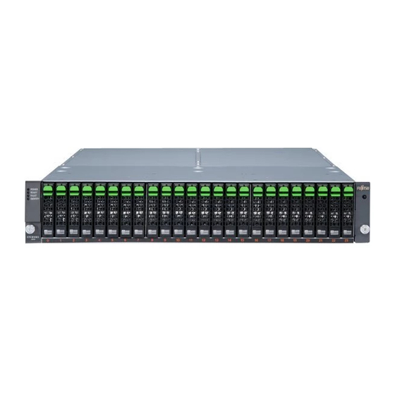
This section describes the position and meaning of the operating and indicator elements on the ETERNUS JX40 S2 storage subsystem. Front Side An operation panel is installed in the front of the ETERNUS JX40 S2 storage subsystem. Figure 10: Front of the ETERNUS JX40 S2 2.5" (disk slot numbering below) Figure 11: Front of the ETERNUS JX40 S2 3.5"... -
Page 34: Operation Panel
4. Power LED LED Status Meaning Identify (blinks blue) Specifies the installation location of the storage subsystem. Fault (amber) The drive enclosure is in error status. Power (green) DC power is supplied to the drive enclosure. Operating Manual ETERNUS JX40 S2... -
Page 35: Disk Leds
Figure 13: Disk LEDs LED Status Meaning Ready (green) The disk drive is in normal status. (blinks green) Fault (amber) The disk drive is in error status. (blinks amber) Identifies the location of the drive. Operating Manual ETERNUS JX40 S2... -
Page 36: Rear Side
Rear Side Operating and Indicator Elements Rear Side Figure 14: Rear side of the ETERNUS JX40 S2 1. I/O module (IOM#0) 2. Cover 3. Mini SAS HD IN Port 4. Mini SAS HD OUT Port 5. Power supply unit (PSU#0) 6. -
Page 37: I/O Module
I/O Module The I/O module is a component that controls how the controller and the drives interact. Figure 15: I/O module of the ETERNUS JX40 S2 1. SAS IN port 2. SAS IN fault LED 3. SAS IN link LED 4. - Page 38 Operating and Indicator Elements LED Status Meaning Ready (green) The I/O module is in normal status. Identify (blinks blue) Identifies the installation location of the I/O module. Fault (amber) The I/O module is in error status. Operating Manual ETERNUS JX40 S2...
-
Page 39: Power Supply Unit (Psu)
The power supply unit transforms input AC power from a power socket to DC power and supplies power to each component. Each power supply unit contains fans. Figure 16: Power supply unit (PSU) of the ETERNUS JX40 S2 1. Power LED 2. Fault LED 3. - Page 40 Rear Side Operating and Indicator Elements This page intentionally is left blank for printing reasons. Operating Manual ETERNUS JX40 S2...
-
Page 41: Hard Disk Drives
Hard Disk Drives The ETERNUS JX40 S2 storage subsystem can accommodate up to 24 2.5" and up to 12 3.5" hard disk drives. Handling Hard Disk Drives Hard disk drives are highly sensitive electromagnetic devices and must be handled with great care. It is extremely likely that an incorrect handling will lead to a partially and/or total failure of the hard disk drives. -
Page 42: Removing/Installing Hard Disk Drive/Drive Dummy
Removing/Installing Hard Disk Drive/Drive Dummy The hard disk drives which can be ordered for the ETERNUS JX40 S2 storage subsystem are delivered pre-installed in frames. Removing a hard disk drive from the frame may only be done in authorized repair centers. -
Page 43: Figure 19: 3.5" Hard Disk Drive In Frame
Keep a drive dummy for future use. If you remove the hard disk drive again and do not fit a replacement, you must put back the dummy drive because of cooling. Operating Manual ETERNUS JX40 S2... -
Page 44: Figure 21: Removing/Installing A 2.5" Hard Disk Drive
Ê Press the green push button of the disk drive and open the lock lever. Ê Hold the lock lever and pull the disk drive. Installing a hard disk drive CAUTION! The hard disk drive must be acclimatized in its operating environment for an acclimatization time. Operating Manual ETERNUS JX40 S2... - Page 45 Ê Push the disk drive with the lever opened into the empty bay until it stops. Ê Return the lock lever. A clicking sound from it indicates that it is locked. Operating Manual ETERNUS JX40 S2...
- Page 46 Removing/Installing Hard Disk Drive/Drive Dummy Hard Disk Drives This page intentionally is left blank for printing reasons. Operating Manual ETERNUS JX40 S2...
-
Page 47: Connections
Connections If you would like to put the ETERNUS JX40 S2 storage subsystem into operation, the SAS and the power supply connections must be inserted. SAS Connection The required connections are on the rear panel of the storage subsystem. Use the approved SAS cables for the host connection of the ETERNUS JX40 S2. - Page 48 SAS Connection Connections Figure 23: SAS connections of an ETERNUS JX40 S2 I/O module (Mini SAS HD ports) 1. SAS IN port 2. SAS OUT port Ê Set up the data connection between the server and the storage subsystem by inserting the Mini SAS HD plug of the SAS cable coming from the server into the SAS IN port connector of the ETERNUS JX40 S2 storage subsystem.
-
Page 49: Power Supply Connection
Ê Plug the other end of the power cables into a safety socket on the rack power supply socket strip. Ensure that at least one power supply unit of the ETERNUS JX40 S2 storage subsystem and one power supply unit of the server attached to the subsystem are connected with the same phase. - Page 50 This page intentionally is left blank for printing reasons.
-
Page 51: Configurations
Configurations Basic RAID controller / HBA configuration Configurations Guideline The ETERNUS JX40 S2 2.5" or 3.5" are mixable up to 4 shelves per chain. The following configuration drawings are valid for both or mixed subsystems. Supported SAS controllers: – Fujitsu PSAS CP400e or LSI SAS9200-8e 6Gb/s 8ext PCIe FH/LP SAS –... -
Page 52: Raid Controller / Hba Configuration And Maximal Storage Configuration
Figure 27: RAID controller / HBA configuration and up to 8 / 4 enclosures ● PRIMERGY server with RAID controller or host bus adapter. ● ETERNUS JX40 S2 storage subsystem(s) with one I/O module. Operating Manual ETERNUS JX40 S2... -
Page 53: Raid Controller / Hba Configuration With Two Way Storage
Figure 28: Redundant host bus adapter and redundant I/O module with two way storage configuration PRIMERGY server with two host bus adaptors ● ETERNUS JX40 S2 storage subsystem(s) with two I/O modules. ● Operating Manual ETERNUS JX40 S2... -
Page 54: Redundant Controller And Storage Two Way Configuration
2nd ... 4th shelf(s) optional shelf(s) optional Figure 29: Redundant HBA and redundant storage two way configuration ● PRIMERGY server with two dual host bus adapters. ETERNUS JX40 S2 storage subsystem(s) with two I/O modules. ● Operating Manual ETERNUS JX40 S2... -
Page 55: Redundant Controller And Storage With File Sharing
2nd ... 4th shelf(s) optional shelf(s) optional Figure 30: Redundant HBA and redundant storage file sharing configuration ● PRIMERGY servers with two host bus adapters. ETERNUS JX40 S2 storage subsystems with two I/O modules. ● Operating Manual ETERNUS JX40 S2... - Page 56 Redundant controller and storage with file sharing Configurations This page intentionally is left blank for printing reasons. Operating Manual ETERNUS JX40 S2...
-
Page 57: Fault Clearing
If you cannot rectify the fault, proceed as follows: Ê Note the steps that you have performed and the state which was active when the error occurred. Note also any error message which may have been displayed. Ê Contact our service organization. Operating Manual ETERNUS JX40 S2... -
Page 58: Problem Solutions And Tips
Their possible causes are named and there are instructions for fault clearing. Please contact the Fujitsu Service Desk first. Our service engineers will help you to diagnose defects and malfunctions and they are often capable of eliminating the malfunction by advice via phone. -
Page 59: I/O Module (Iom)
SAS connection problems indicated by them. If the fault LED (amber LED) on a IOM is on, the IOM is defective. Ê Before you replace the defective IOM, please contact the Fujitsu Service Desk first. -
Page 60: The Eternus Jx40 S2 Does Not Power On With The Attached Server
Ê The PSU power switches must be set to ON. Incorrect cabling Ê Ensure that the SAS cabling is correct (SAS IN port); the ETERNUS JX40 S2 is powered on by SAS link from the Server. Operating Manual ETERNUS JX40 S2... -
Page 61: Replacing Components
(see section "Power Supply Connection" on page 49). The ETERNUS JX40 S2 has two power supply units, which makes it possible for a failed unit to be replaced while the system is running. Each power supply unit contains fans. CAUTION! When replacing a power supply unit, do not leave it removed for longer than 5 minutes to prevent temperature rise. - Page 62 Ê Connect the lead to the power supply unit and set the AC cord clamp. Ê Connect the power cable to the mains. Ê Verify that the Power LED of the unit shows green light. Operating Manual ETERNUS JX40 S2...
-
Page 63: I/O Module
SAS cable comes and disconnect and connect the cable plug at this OUT port. Ê Verify that the status LED of the I/O module shows a normal status after not exceeding 10 minutes. Operating Manual ETERNUS JX40 S2... -
Page 64: Operation Panel
Ê Remove some disks nearest to the operation panel in order to have free mounting place for unscrewing the operation panel. Operation panel Figure 33: Screw to be loosened for removing the 2.5" operation panel Operating Manual ETERNUS JX40 S2... - Page 65 Figure 34: Screw to be loosened for removing the 3.5" operation panel Ê Loosen the screw holding the operation panel. Ê Carefully take off the operation panel for some millimeters. Figure 35: Ribbon cable connecting the operation panel Operating Manual ETERNUS JX40 S2...
- Page 66 Operation Panel Replacing Components Ê Remove the ribbon cable connecting the operation panel. Ê Mont the new operation panel in reverse order. Install the disks as recorded when you removed them. Operating Manual ETERNUS JX40 S2...
-
Page 67: Abbreviations
Advanced Configuration and Power management Interface ANSI American National Standard Institute ASR&R Automatic Server Reconfiguration and Restart Advanced Technology Attachment Battery Backup Unit BIOS Basic Input-Output System Baseboard Management Controller Cache Coherency Cylinder Head Sector CMOS Complementary Metal Oxide Semiconductor Operating Manual ETERNUS JX40 S2... - Page 68 Dual Inline Memory Module Dual Inline Package Direct Memory Access Desktop Management Interface DRAM Dynamic Random Access Memory Error Checking and Correcting Extensible Firmware Interface Electromagnetic Compatibility Electromagnetic interference Emergency Management Port EMRL Embedded RAID Logic Operating Manual ETERNUS JX40 S2...
- Page 69 Electrostatic Sensitive Devices, ElectroStatic Discharge EVRD Enterprise VRD Front Panel Controller Field Replaceable Unit Front Side Bus Graphical User Interface Host Bus Adapter Hard Disk Drive Hot-plug Controller Hot-swap Controller I²C Inter-Integrated Circuit Input/Output Intelligent Chassis Management Identification Operating Manual ETERNUS JX40 S2...
- Page 70 Intelligent Platform Management Bus IPMI Intelligent Platform Management Interface iRMC integrated Remote Management Controller Interrupt Request Line Local Area Network Logical Block Address Liquid Crystal Display Logical Unit Number Low-Voltage Differential SAS Multi-Mode Fiber Manual-Retention Latch Operating Manual ETERNUS JX40 S2...
- Page 71 Programmed Input Output Programmable Logic Device POST Power-On Self Test PS(U) Power Supply (Unit) RAID Redundant Arrays of Independent Disks RoHS Restriction of the Use of Certain Hazardous Substances (Waste from Electric and Electronic Equipment, EU guideline) Operating Manual ETERNUS JX40 S2...
- Page 72 Remote Test and Diagnostics System SAF-TE SCSI-Accessed Fault-Tolerance Enclosures Serial Attached SCSI SATA Serial ATA Single-Bit Error Single Connector Attachment SCSI Small Computer System Interface Sensor Data Record SDRAM Synchronous Dynamic Random Access Memory System Event Log Operating Manual ETERNUS JX40 S2...
- Page 73 Solid State Disk System Setup Utility SVGA Super Video Graphics Adapter UHCI Unified Host Controller Interface Universal Serial Bus WEEE Waste from Electric and Electronic Equipment (EU directive) Wired for Management Wake up On LAN Operating Manual ETERNUS JX40 S2...
- Page 74 Abbreviations This page intentionally is left blank for printing reasons. Operating Manual ETERNUS JX40 S2...
-
Page 75: Figures
Disk LEDs ......Figure 14: Rear side of the ETERNUS JX40 S2 ... Figure 15: I/O module of the ETERNUS JX40 S2 . - Page 76 Removing/installing a 3.5" hard disk drive ..Figure 23: SAS connections of an ETERNUS JX40 S2 I/O module (Mini SAS HD ports) ....
-
Page 77: Tables
Table 1: Notation conventions ..... Table 2: Acclimatization time for the hard disk drives ..Operating Manual ETERNUS JX40 S2... - Page 78 Tables Operating Manual ETERNUS JX40 S2...
-
Page 79: Related Publications
PDF files from the Internet. The overview page showing the online documentation available on the Internet can be found via the URL: http://manuals.ts.fujitsu.com/. For the documentation of the PRIMERGY servers and of the PRIMERGY ServerView Suite choose the navigation point X86 Servers. - Page 80 Related publications Operating Manual ETERNUS JX40 S2...
-
Page 81: Index
SAS connection SAS controllers saving energy I/O module ServerView spring nut replace structure of the manual support bracket labels low voltage directive unpacking upgrade I/O module manufacturer’s notes power supply unit MatrixEP Operating Manual ETERNUS JX40 S2... - Page 82 Index Operating Manual ETERNUS JX40 S2...