Table of Contents
Advertisement
Quick Links
Form No. 3364-529 Rev A
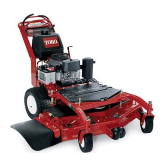
Commercial Walk-Behind Mower
Floating Deck, Split Lever, Hydro Drive with
36in or 48in TURBO FORCE
®
Cutting Unit
Model No. 39484—Serial No. 311000001 and Up
Model No. 39488—Serial No. 311000001 and Up
g014653
To register your product or download an Operator's Manual or Parts Catalog at no charge, go to www.Toro.com.
Original Instructions (EN)
Advertisement
Table of Contents

Related Manuals for Toro 39488

Summary of Contents for Toro 39488
- Page 1 36in or 48in TURBO FORCE ® Cutting Unit Model No. 39484—Serial No. 311000001 and Up Model No. 39488—Serial No. 311000001 and Up g014653 To register your product or download an Operator's Manual or Parts Catalog at no charge, go to www.Toro.com. Original Instructions (EN)
-
Page 2: Introduction
Whenever you need service, genuine Toro parts, or additional information, contact an Authorized Service Dealer or Toro Customer Service and have the model and serial numbers of your product ready. Figure 1 identifies the location of the model and serial numbers on the product. -
Page 3: Table Of Contents
Safety ................4 Servicing the Brake..........36 Safe Operating Practices ........4 Belt Maintenance............ 37 Toro Mower Safety ..........5 Replacing the Mower Belt ........37 Slope Indicator............. 7 Replacing the PTO Drive Belt......37 Safety and Instructional Decals ......8 Adjusting the PTO Drive Belt Idler Spring Product Overview ............ -
Page 4: Safety
Safety – Never remove gas cap or add fuel with engine running. Allow engine to cool before refueling. Do not smoke. Note: The addition of attachments made by other manufacturers that do not meet American – Never refuel or drain the machine indoors. National Standards Institute certification will cause •... -
Page 5: Toro Mower Safety
Toro Mower Safety attachment bolts. Keep equipment in good condition. The following list contains safety information specific to Toro products and other safety information you must • Never tamper with safety devices. Check safety know. systems for proper operation before each use. - Page 6 • Use only genuine replacement parts to ensure that original standards are maintained. • Check brake operation frequently. Adjust and service as required.
-
Page 7: Slope Indicator
Slope Indicator G011841 Figure 3 This page may be copied for personal use. 1. The maximum slope you can safely operate the machine on is 20 degrees. Use the slope chart to determine the degree of slope of hills before operating. Do not operate this machine on a slope greater than 20 degrees. Fold along the appropriate line to match the recommended slope. -
Page 8: Safety And Instructional Decals
Safety and Instructional Decals Safety decals and instructions are easily visible to the operator and are located near any area of potential danger. Replace any decal that is damaged or lost. 98-5954 43-8480 Battery Symbols Some or all of these symbols are on your battery 1. - Page 9 Manufacturer’s Mark 1. Indicates the blade is identified as a part from the original machine manufacturer. 104-8186 48in mower decks 110-2067 104-8569 110-2068 105-7798 1. Read the Operator’s Manual. 106-0635 112-8720 106-0699...
- Page 10 115-4212 115-4186 1. Hydraulic oil level 3. Warning—do not touch 1. Interval the hot surface. 2. Power Take-off (PTO) 2. Read the Operator’s 3. Parking brake Manual. 4. Neutral 5. Operator presence switch 6. Battery 117–2718 115–4179 1. Move the motion control lever to the neutral position, then pull 6.
-
Page 11: Product Overview
114-3424 1. Traction control 5. Reverse 3. Slow 2. Fast 4. Neutral 6. Disengage the PTO (Power Take Off) Product Overview Figure 5 1. Ignition switch 6. Choke 2. Left motion control lever 7. Neutral lock position for right motion control lever g014654 3. -
Page 12: Specifications
Contact your Authorized Service Dealer or Distributor or go to www.Toro.com for a list of all approved attachments and accessories. Specifications Note: Specifications and design are subject to change without notice. Figure 6 36 inch mowers: 1. -
Page 13: Operation
Operation DANGER In certain conditions during fueling, static Adding Fuel electricity can be released causing a spark which can ignite the gasoline vapors. A fire or explosion Use Unleaded Regular Gasoline suitable for from gasoline can burn you and others and can automotive use (85 pump octane minimum). -
Page 14: Checking The Engine Oil Level
Note: A fuel stabilizer/conditioner is most CAUTION effective when mixed with fresh gasoline. To Children or bystanders may be injured if they minimize the chance of varnish deposits in the fuel move or attempt to operate the machine while it system, use fuel stabilizer at all times. -
Page 15: Operating The Mower Blade Control (Pto)
Operating the Mower Blade Control (PTO) The blade control switch (PTO) is used in conjunction with the right side motion control lever to engage and disengage the mower blades. Engaging the Mower Blades (PTO) 1. To engage the mower blades, move the right side motion control lever to the center, un-locked position (Figure 9). -
Page 16: The Safety Interlock System
The Safety Interlock System 2. Set the parking brake. 3. Move the right side motion control lever to the CAUTION center, un-locked position. The blades should not rotate. If safety interlock switches are disconnected or damaged the machine could operate unexpectedly 4. -
Page 17: Stopping The Machine
2. Move the right side motion control lever to the the neutral lock position, disengage the power take off center, un-locked position. (PTO), and turn the ignition key to off. 3. To go forward, slowly push the motion control Set the parking brake when you leave the machine; refer levers forward (Figure 11). -
Page 18: Transporting Machines
Figure 13 1. Traction unit tie down loop Figure 12 1. Pump by-pass valve Side Discharging or Mulching the Grass 3. Release the parking brake. This mower has a hinged grass deflector that disperses 4. Push the machine to the desired location. clippings to the side and down toward the turf. -
Page 19: Adjusting The Anti-Scalp Rollers
1. Select hole in height-of-cut post and number of (10 mm) clearance above the ground (Figure 15, spacers corresponding to the height-of-cut desired Figure 16, Figure 17). (Figure 14). 2. If adjustment is needed, remove the bolt, washers 2. Using the lift handle, raise side of deck and remove and nut (Figure 15, Figure 16, Figure 17). -
Page 20: Adjusting The Flow Baffle
1. Disengage the PTO, move the motion control levers to the neutral locked position and set the parking brake. 2. Stop the engine, remove the key, and wait for all moving parts to stop before leaving the operating position. 3. To adjust the cam lock, swing the lever up to loosen the cam lock (Figure 18). - Page 21 • Use in tall, dense grass mowing conditions. • Use in wet conditions. • Lowers the engine power consumption. • Allows increased ground speed in heavy conditions. • This position is similar to the benefits of the Toro SFS mower.
-
Page 22: Using The Mid-Size Weight
Using the Mid-Size Weight Weights are installed on certain mowers to improve balance and improve performance. The weights can be moved or removed to create optimized performance under different mowing conditions and for operator preference (Figure 22 or Figure 23). The following table indicates the position of the weight as installed at the factory. -
Page 23: Maintenance
Every 250 hours • Grease the front wheel bearings (more often in dirty or dusty conditions). Every 400 hours • Change the hydraulic filter and hydraulic oil when using Toro® HYPR-OIL™ 500 Every 500 hours hydraulic oil. • Paint chipped surfaces. -
Page 24: Lubrication
Lubrication Greasing the PTO Drive Belt Idler and Mower Deck Belt Grease with No. 2 general purpose lithium base or Idler molybdenum base grease. Service Interval: Every 50 hours How to Grease Every 50 hours 1. Disengage the PTO and set the parking brake. Grease the idler pulley pivots (Figure 25 or Figure 26). -
Page 25: Engine Maintenance
Engine Maintenance Servicing the Air Cleaner Service Interval/Specification Service Interval: Every 25 hours—Clean foam air cleaner element. Every 50 hours—Check the paper air cleaner element. Every 200 hours—Replace the paper air cleaner element. Note: Service the air cleaner more frequently (every Figure 27 few operating hours) if the operating conditions are 1. -
Page 26: Servicing The Engine Oil
Servicing the Engine Oil Service Interval/Specification Service Interval: Before each use or daily—Check the engine oil level. After the first 8 hours—Change the engine oil. Every 100 hours—Change the engine Figure 29 oil. 1. Oil dipstick 2. Filler tube Every 200 hours—Change the oil filter. -
Page 27: Servicing The Spark Plugs
4. Install the replacement oil filter to the filter adapter, turn the oil filter clockwise until the rubber gasket contacts the filter adapter, then tighten the filter an additional 3/4 turn (Figure 31). 5. Fill the crankcase with the proper type of new oil; refer to Servicing the Engine Oil. -
Page 28: Fuel System Maintenance
Checking the Spark Plugs Fuel System 1. Look at the center of the spark plugs (Figure 33). Maintenance If you see light brown or gray on the insulator, the engine is operating properly. A black coating on the insulator usually means that the air cleaner is dirty. Draining the Fuel Tank 2. -
Page 29: Servicing The Fuel Filter
Figure 34 1. Fuel filter 3. Fuel shut-off valve Figure 35 2. Clamp 1. Hose clamp 3. Filter 2. Fuel line Servicing the Fuel Filter 5. Remove the filter from the fuel lines. Service Interval: Every 200 hours/Yearly (whichever 6. Install a new filter and move the hose clamps close comes first) to the filter. -
Page 30: Electrical System Maintenance
Electrical System WARNING Maintenance Incorrect battery cable routing could damage the machine and cables causing sparks. Sparks can cause the battery gasses to explode, resulting in Servicing the Battery personal injury. • Always Disconnect the negative (black) battery Always keep the battery clean and fully charged. Use cable before disconnecting the positive (red) a paper towel to clean the battery case. - Page 31 Figure 37 1. Vent caps 3. Lower line 2. Upper line 2. If the electrolyte is low, add the required amount of distilled water; refer to Adding Water to the Battery in Electrical System Maintenance (page 30). Adding Water to the Battery The best time to add distilled water to the battery is just before you operate the machine.
-
Page 32: Servicing The Fuses
Important: Always keep the battery fully charged (1.265 specific gravity). This is especially important to prevent battery damage when the temperature is below 32°F (0°C). 1. Remove the battery from the chassis; refer to Removing the Battery. 2. Check the electrolyte level; refer to Checking the Electrolyte Level. -
Page 33: Drive System Maintenance
Drive System Maintenance Adjusting the Tracking 1. If the machine does not track straight, adjustment is required. 2. Check the rear tire pressure. Refer to Checking the Tire Pressure. Figure 41 3. Loosen the wing nuts on the right control rod and rotate the turnbuckle in or out to ensure the right side control lever is centered in the neutral lock position. -
Page 34: Servicing The Caster Wheel And Bearings
Remember the location of the spacers on each fork 1. Remove the locknut and wheel bolt holding the to ensure correct installation, and to maintain a level caster wheel to the caster fork (Figure 44). deck. 4. Insert a pin punch into the mounting tube and carefully drive out the bushings (Figure 43). -
Page 35: Cooling System Maintenance
Cooling System assembly. Make sure it is between the armature and the rotor friction surfaces. Maintenance 2. Tighten the lock nuts until there is slight binding on the feeler gauge but it can be moved easily within the air gap (Figure 45). Cleaning the Air Intake Screen 3. -
Page 36: Brake Maintenance
Brake Maintenance 9. Tighten the top and bottom jam nuts (Figure 46). 10. Check the brake operation again; refer to Checking the Brake. Servicing the Brake Before each use, check brakes on both a level surface and slope. Always set the parking brake when you stop the machine or leave it unattended. -
Page 37: Belt Maintenance
Belt Maintenance Replacing the Mower Belt Service Interval: Every 50 hours Squealing when the belt is rotating, blades slipping when cutting grass, frayed belt edges, burn marks and cracks are signs of a worn deck belt. Replace the deck belt if any of these conditions are evident. -
Page 38: Adjusting The Pto Drive Belt Idler Spring Anchor
are signs of a worn drive belt. Replace the drive belt if any of these conditions are evident. 1. Disengage the PTO and set the parking brake. 2. Stop the engine, remove the key, and wait for all moving parts to stop before leaving the operating position. -
Page 39: Replacing The Pump Drive Belt
Use Figure 51 for the idler position options. Figure 52 1. Hydraulic pumps 5. Clutch wire connector Figure 51 2. Idler pulley 6. Pivot bolt 3. Clutch retainer 7. Drive pulley 1. PTO drive belt idler pulley 4. Most tension for worn belts 4. -
Page 40: Controls System Maintenance
Controls System Maintenance Adjusting the Motion Control Handle Positions Adjusting the Right Side Motion Control Lever If the motion control levers do not align horizontally, adjust the right side motion control lever. Note: Adjust the horizontal alignment before the front to back alignment. - Page 41 Figure 55 1. Right side motion control 3. 1/16 inch to 3/32 inch Figure 56 lever pivot shown under (1.6 mm to 2.4 mm) gap controls needed between switch 1. Left motion control lever 3. Neutral locked position and control lever 2.
-
Page 42: Hydraulic System Maintenance
Every 250 hours—Change the hydraulic filter and hydraulic oil when using Mobil ® 1 oil. Every 500 hours—Change the hydraulic filter and hydraulic oil when using Toro ® HYPR-OIL ™ hydraulic oil. Figure 58 1. Cap 3. Cold fluid level-full WARNING 2. - Page 43 check for leaks. If one or both wheels will not drive, refer to Bleeding Hydraulic System. 11. Recheck level and add fluid, if required. Do not overfill. Bleeding the Hydraulic System The traction system is self bleeding, however, it may be necessary to bleed the system if fluid is changed or after work is performed on the system.
-
Page 44: Mower Deck Maintenance
Mower Deck WARNING Hydraulic fluid escaping under pressure can Maintenance penetrate skin and cause injury. • If hydraulic fluid is injected into the skin it Servicing the Cutting Blades must be surgically removed within a few hours by a doctor familiar with this type of injury. To ensure a superior quality of cut, keep the blades Gangrene may result if this is not done. - Page 45 Figure 62 48 inch Mower Deck shown 2. Position A 1. Measure here from blade to hard surface Figure 61 1. Cutting Edge 3. Wear/slot forming in curved area 2. Sail 4. Crack in the curved area 2. Inspect the blades, especially the curved area (Figure 61).
- Page 46 Blades must be replaced if a solid object is hit, if the blade is out of balance or is bent. To ensure optimum performance and continued safety conformance of the machine, use genuine Toro replacement blades. Replacement blades made by other manufacturers may result in non-conformance with safety standards.
-
Page 47: Correcting The Mower Quality Of Cut
Frame Set Up Checking the Carrier Frame and Engine Deck Alignment Figure 67 Note: Misalignment can cause excess wear on the PTO 1. Blade 2. Balancer drive belt. 1. Disengage the PTO and set the parking brake. Installing the Blades 2. - Page 48 Checking the Engine Deck Height 1. Disengage the PTO and set the parking brake. 2. Stop the engine, remove the key, and wait for all moving parts to stop before leaving the operating position. 3. Adjust the tire pressure in the rear tires to specifications;...
-
Page 49: Checking The Mower Deck Front-To-Rear Pitch
Figure 73 Figure 71 36 inch Mower Deck shown 1. Caster Wheel 4. Same height at locations A and B 2. Carrier Frame 5. Caster spacers 3. Front height-of-cut pins Changing the Mower Deck Front-to-Rear Pitch Checking the Mower Deck Changing the front-to-rear pitch is done by adjusting the front height-of-cut posts. -
Page 50: Checking The Mower Deck Side-To-Side Height
Checking the Mower Deck 2. Adjust the caster spacer. Side-to-Side Height 3. Recheck the front-to-rear pitch and side to side leveling of the cutting unit. 1. Adjust the rear tire pressure to specifications; refer to Drive System Maintenance (page 33) . Matching Height of Cut 2. -
Page 51: Replacing The Grass Deflector
Important: The grass deflector must be able B. Adjust the caster fork spacers. to rotate. Lift the deflector up to the full open C. Adjust the front mower deck support pins. position and ensure that it rotates into the full 6. -
Page 52: Cleaning
Cleaning Storage Cleaning and Storage Cleaning Under the Mower 1. Disengage the power take off (PTO), set the parking Service Interval: Before each use or daily brake, and turn the ignition key to off. Remove the key. Remove the grass buildup under the mower daily. 2. - Page 53 distribute the oil inside the cylinder. Install the spark plug(s). Do not install the wire on the spark plug(s). 10. Check and tighten all bolts, nuts, and screws. Repair or replace any part that is damaged or defective. 11. Paint all scratched or bare metal surfaces. Paint is available from your Authorized Service Dealer.
-
Page 54: Troubleshooting
Troubleshooting Problem Possible Cause Corrective Action Engine will not start, starts hard, or fails 1. Fuel tank is empty. 1. Fill fuel tank with gasoline. to keep running. 2. Choke is not on. 2. Move the choke lever to choke position. 3. - Page 55 Problem Possible Cause Corrective Action Blades do not rotate. 1. Drive belt is worn, loose or broken. 1. Check the belt tension. 2. Drive belt is off pulley. 2. Install drive belt and check adjusting shafts and belt guides for correct position.
-
Page 56: Schematics
Schematics Hydraulic Schematic (Rev. A) - Page 57 Electrical Schematic (Rev. A)
- Page 58 Notes:...
- Page 59 Notes:...
- Page 60 Countries Other than the United States or Canada Customers who have purchased Toro products outside the United States or Canada should contact their Toro Distributor (Dealer) to obtain guarantee policies for your country, province, or state. If for any reason you are dissatisfied with your Distributor’s service or have difficulty obtaining guarantee information, contact the Toro importer.