Table of Contents
Advertisement
Quick Links
General Installation Manual
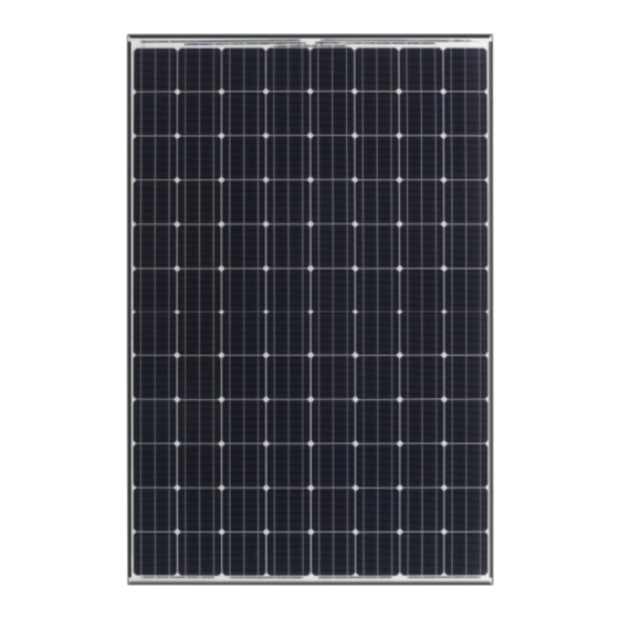
Photovoltaic Module HIT
VBHNxxxSA series
VBHNxxxKA series
Model No.
・VBHNxxxSA17
xxx=340, 335, 330, 325
・VBHNxxxKA03
xxx=325, 320
VBHNxxxSA17 series
Thank you for choosing Panasonic photovoltaic module HIT
Please read this manual completely before you install or use of
®
HIT
. With proper operation and maintenance, HIT
vide you with clean, renewable solar electricity for many years.
This manual contains important installation, maintenance and
safety information. The word "module" as used in this manual
refers to one or more PV modules. Retain this manual for
future reference.
®
VBHNxxxKA03 series
®
.
®
will pro-
CONTENTS
"HIT" is a trademark of the Panasonic Group.
Other product and service names listed in this
manual are trademarks or registered trademarks
of respective companies.
2
3
6
8
13
13
13
Advertisement
Table of Contents

Summary of Contents for Panasonic VBHNxSA series
-
Page 1: Table Of Contents
DISCLAIMER OF LIABILITY VBHNxxxKA03 series VBHNxxxSA17 series CONTACT INFORMATION ® Thank you for choosing Panasonic photovoltaic module HIT Please read this manual completely before you install or use of ® ® . With proper operation and maintenance, HIT will pro- vide you with clean, renewable solar electricity for many years. -
Page 2: Safety Precautions
PV module and make a replace- For a non-integral module or panel, installed by Panasonic. There are no ment, when scratch exposing con- the assembly is to be mounted over user serviceable parts within the... -
Page 3: Module Specifications
MECHANICAL LOADING ・ 61 psf(230-380mm range from edge) 60904-3. Note: At the time of ship- ment, Panasonic guarantees the The modules should be mounted at ・ 75 psf (230-345mm range from edge) output level of its modules to be -0/... - Page 4 Table 1. Model Specifications Electrical Specifications Model VBHN340SA17 VBHN335SA17 VBHN330SA17 VBHN325SA17 VBHN325KA03 VBHN320KA03 Cell Number in Series Rated Power, Watts (Pmax) Maximum Power Voltage (Vpm) 59.7 59.4 58.0 57.6 59.2 58.7 Maximum Power Current (Ipm) 5.70 5.65 5.70 5.65 5.50 5.46 Open Circuit Voltage (Voc) 71.3...
-
Page 5: Standards
ing connector for series and string ules and must be purchased sepa- STANDARDS connections. Always use these con- rately. VBHNxxxSA and VBHNxxxKA series com- nectors and do not detach them BYPASS DIODE ply with the requirements of UL1703. from cables. ... -
Page 6: Installation
Conditions. An installation location with conditions beyond the Operating Condi- tions or with other Special Conditions (see below) should be avoided. Operat- ing Conditions of Panasonic modules are as follows: Figure 4. Fixing of cables and connectors 1) The modules should be operated only in terrestrial applications. -
Page 7: Module Installation
Sleeves; 6000 Aluminum alloys will reasonably protect against a risk of electrolytic corrosion. Panasonic does not provide a war- Note: Please refer to IronRidge ranty for clamps. The module war- manual, for installation method. -
Page 8: Wiring
(Maximum Power Point Tracking) confirming the polarity of it is cor- aged. charge controller is required. Note: rect. Panasonic HIT 96-cell modules have Do not insert PV cable between a higher Voc than conventional 60- Connectors between modules must... -
Page 9: Earth Ground Wiring
(nuts, bolts, star washers, spilt- EARTH GROUND WIRING Lay-in lugs or grounding clips can be ring lock washers, flat washers and used to ground Panasonic PV mod- A module with exposed conductive the like) is used to attach a listed ules. - Page 10 and the cup washer) so that the cup Using bolt and nut Using cup washers washer doesn’t contact the module (see Figures 6.2) (see Figures 6.2) frame and is fixed stably to the module frame. • The use of cup washers is to prevent If using this method, use one of the wire from slipping out from under the larger holes with diameter of...
- Page 11 10-14AWG-Solid -> 20 in-lbs, Using a lay-in lug with bolt and 4-6AWG-Strand -> 35 in-lbs, (see Figure 6.3) 8AWG-Strand -> 25 in-lbs, 10- 14AWG-Strand -> 20 in-lbs If using this method, please follow instructions in previous section re- Burndy L L C CL501TN 14AWG- garding using bolts and nuts with Solid ->...
- Page 12 For more information, please refer to Using a Grounding Clip with bolt Instruction sheet issued by Tyco Electron- and nut (see Figure 6.4) ics. Use Tyco Electronics 1954381-2 as grounding clip. Place the grounding clip onto the module frame. ...
-
Page 13: Maintenance
© SANYO Electric Co., Ltd. 2019 aid treatment. SANYO is part of the Panasonic Group. To remove persistent dirt, the mod- IMA001-1219-2.4 ule can be washed with a micro- fiber cloth and ethanol. - Page 14 ・Add models of VBHN340SA17 and VBHN335SA17 Ver.2.1 2018.12.5 Addition of models ・Add electrical specifications of VBHN340SA17 and VBHN335SA17 Panasonic Eco Solutions of North Ameri- Ver.2.2 2019.4.1 The company name change ca →Panasonic Life Solutions Company of America Ver.2.3 2019.9.30...


