
Related Manuals for Siemens RUGGEDCOM WIN5151 Series


Summary of Contents for Siemens RUGGEDCOM WIN5151 Series
- Page 1 Preface Introduction Installing the Subscriber Unit RUGGEDCOM WIN5151 Device Management Technical Specifications Certification Installation Guide 10/2018 RC1189-EN-05...
- Page 2 Warranty Siemens warrants this product for a period of five (5) years from the date of purchase, conditional upon the return to factory for maintenance during the warranty term. This product contains no user-serviceable parts. Attempted service by unauthorized personnel shall render all warranties null and void.
-
Page 3: Table Of Contents
RUGGEDCOM WIN5151 Installation Guide Table of Contents Table of Contents Preface ......................Alerts ..............................v Related Documents ..........................vi Training .............................. vi Customer Support ..........................vi Chapter 1 Introduction ..................... 1.1 Feature Highlights ........................2 1.2 Description ........................... 2 1.3 Required Tools and Materials ...................... - Page 4 RUGGEDCOM WIN5151 Table of Contents Installation Guide Chapter 3 Device Management ..................3.1 Configuring the Subscriber Unit ....................27 Chapter 4 Technical Specifications .................. 4.1 Power Supply Requirements ......................29 4.2 Power Consumption ........................30 4.3 Radio and Modem Specifications ....................30 4.4 Operating Environment ....................... 30 4.5 Mechanical Specifications ......................
-
Page 5: Preface
RUGGEDCOM WIN5151 Installation Guide Preface Preface This guide describes the RUGGEDCOM WIN5151. It describes the major features of the subscriber unit, installation, commissioning and important technical specifications. It is intended for use by subscriber unit installers and operators, and assumes readers have a working knowledge of WiMAX technologies and procedures. -
Page 6: Related Documents
Siemens Sales representative. Customer Support Customer support is available 24 hours, 7 days a week for all Siemens customers. For technical support or general information, contact Siemens Customer Support through any of the following methods: Online Visit http://www.siemens.com/automation/support-request... -
Page 7: Introduction
RUGGEDCOM WIN5151 Chapter 1 Installation Guide Introduction Introduction The RUGGEDCOM WIN5151 subscriber unit is part of the RUGGEDCOM WIN family, a line of mobile WiMAX broadband wireless access systems based on the IEEE 802.16e mobile WiMAX standard. The RUGGEDCOM WIN5151 is a high-performance, self-learning subscriber. It automatically detects the base station on the best signal available, allowing for plug-and-play installation and maintenance free operation. -
Page 8: Feature Highlights
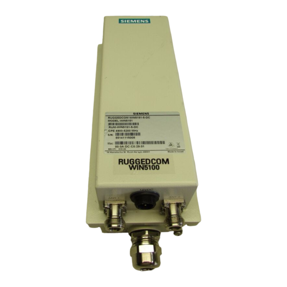
Description The RUGGEDCOM WIN5151 is available in one of two models: • AC Model The AC model receives power from a Siemens-approved PoE injector. • DC Model The DC model receives power directly from a Class 2 power supply. Both variants feature various ports, controls and indicator LEDs for connecting, configuring and troubleshooting the subscriber unit. - Page 9 RUGGEDCOM WIN5151 Chapter 1 Installation Guide Introduction ANT 1 ANT 2 ETH/PWR RSSI RSSI W.LINK W.LINK Figure 1: RUGGEDCOM WIN5151 (AC Model) 1. ANT 1 Port 2. ETH/PWR Port 3. RSSI LEDs 4. W.LINK LED 5. PWR LED 6. ANT 2 Port 7. Chassis Ground 12VDC ANT 1 ANT 2 RSSI ETH/PWR RSSI...
-
Page 10: Required Tools And Materials
Chapter 1 RUGGEDCOM WIN5151 Introduction Installation Guide State Description Green (Solid) Subscriber unit is connected to the base station and receiving services. Green (Blinking) Link between the subscriber unit and the base station is down. PWR LED Indicates when power is supplied to the subscriber unit. State Description Green... - Page 11 RUGGEDCOM WIN5151 Chapter 1 Installation Guide Introduction Decommissioning This device may include sensitive, proprietary data. Before taking the device out of service, either permanently or for maintenance by a third-party, make sure it has been fully decommissioned. For more information, refer to the associated User Guide. Recycling and Disposal For environmentally friendly recycling and disposal of this device and related accessories, contact a facility certified to dispose of waste electrical and electronic equipment.
- Page 12 Chapter 1 RUGGEDCOM WIN5151 Introduction Installation Guide Decommissioning and Disposal...
-
Page 13: Installing The Subscriber Unit
This product contains no user-serviceable parts. Attempted service by unauthorized personnel shall render all warranties null and void. Changes or modifications not expressly approved by Siemens Canada Ltd could invalidate specifications, test results, and agency approvals, and void the user's authority to operate the... -
Page 14: General Procedure
Chapter 2 RUGGEDCOM WIN5151 Installing the Subscriber Unit Installation Guide IMPORTANT! This product should be installed in a restricted access location where access can only be gained by authorized personnel who have been informed of the restrictions and any precautions that must be taken. -
Page 15: Unpacking The Subscriber Unit
Inspect the package for damage before opening it. Visually inspect each item in the package for any physical damage. Verify all items are included. If any item is missing or damaged, contact Siemens for assistance. Section 2.3 Site Preparation and Precautions Before installing the subscriber unit and or antenna(s), it is important to plan the the complete installation and make sure the appropriate safe guards are in place. - Page 16 • Always use the most appropriate mounting method for the site and the equipment being installed. For assistance, contact a Siemens representative. • Always assume an overhead line can cause serious injury or death. Note that electric power lines and phone lines look alike.
-
Page 17: Installing The Subscriber Unit In Hazardous Locations
RUGGEDCOM WIN5151 Chapter 2 Installation Guide Installing the Subscriber Unit Section 2.4 Installing the Subscriber Unit in Hazardous Locations The RUGGEDCOM WIN5151 is designed to comply with the safety standards for Class I, Division 2, Zone 2 hazardous locations where concentrations of flammable gases, vapors or liquids may be present, as opposed to normal operating environments. -
Page 18: Mounting The Subscriber Unit To A Wall Or Tower
Chapter 2 RUGGEDCOM WIN5151 Installing the Subscriber Unit Installation Guide When choosing the mounting location for the unit, consider the available mounting structures and antenna clearance. Site Survey Most wireless networks include many subscriber/base stations installed in various locations in an overlapping radio-cell pattern. -
Page 19: Mounting The Subscriber Unit To A Pole
RUGGEDCOM WIN5151 Chapter 2 Installation Guide Installing the Subscriber Unit Figure 4: Mounting the Subscriber Unit to a Wall or Tower 1. Subscriber Unit 2. Mounting Kit 3. Wall Holder/Pole Mount 4. M8 × 25 mm Hex Screw 5. M8 Spring Washer 6. M8 Flat Washer 7. M8 Nut 8. M5 Flat Washer 9. NS 1/4" × 1/2" HEX Chipboard Screw 10. Wall Anchor Liberally apply an anti-corrosion spray to all galvanized steel components, including mounting brackets, washers and screws. - Page 20 Chapter 2 RUGGEDCOM WIN5151 Installing the Subscriber Unit Installation Guide To mount the subscriber unit to a pole, do the following: Attach the subscriber unit to the mounting bracket. Figure 5: Mounting the Subscriber Unit to a Large Pole 1. Subscriber Unit 2. Pole 3. Clamping Bracket 4. Mounting Bracket 5. M8-25 Hex Screw 6. M8 Spring Washer 7. M8 Flat Washer ...
-
Page 21: Installing The Antennas
RUGGEDCOM WIN5151 Chapter 2 Installation Guide Installing the Subscriber Unit Liberally apply an anti-corrosion spray to all galvanized steel components, including mounting brackets, nuts, washers and screws. Select a mounting location on the pole. Position the mounting bracket against the pole. NOTE When mounting the subscriber unit, note the orientation of the clamping bracket in Figure 5... - Page 22 Chapter 2 RUGGEDCOM WIN5151 Installing the Subscriber Unit Installation Guide • In some cases, the antenna may need to be tilted to make sure the level at which the subscriber unit receives transmissions from the base station (and vice versa) is not too high. When only the last RSSI LED is on, this indicates saturation and the received signal level is too high.
-
Page 23: Grounding The Subscriber Unit
RUGGEDCOM WIN5151 Chapter 2 Installation Guide Installing the Subscriber Unit Section 2.7 Grounding the Subscriber Unit When connecting the ground cable to the subscriber unit, make sure to use a 10 AWG grounding cable and torque the screw to 15 N·m (11 ft. lb.). DANGER! Electrocution hazard –... -
Page 24: Connecting Power Directly (Dc Only)
Electrical hazard – risk of damage to equipment. The power cord provided with the data adapter is safety certified according to national rules. Do not use a power cord that has not been approved by Siemens for use with the data adapter. To connect power and data to the subscriber unit, do the following: CAUTION! Crushing hazard –... -
Page 25: Connecting To A Ruggedcom Rp100 Or Rp110
The lightning protector must meet the necessary requirements of IEC/UL/CSA 60950-1. The clamping voltage must also be less than 60 V and the protector must not activate when the voltage is less than 56 V. For more information about these requirements, contact Siemens Customer Support. IMPORTANT! Install the lightning protector and the RUGGEDCOM RP100/RP110 as close as possible. -
Page 26: Assembling The Poe Connector
Chapter 2 RUGGEDCOM WIN5151 Installing the Subscriber Unit Installation Guide Figure 10: Typical Outdoor Installation 1. RUGGEDCOM WIN5151 2. Shielded Cable 3. Ground Connection 4. Lightning Protector 5. RUGGEDCOM RP100/RP110 6. Drain Wire (Shielded) For more information about the RUGGEDCOM RP100 or RP110, refer to the RUGGEDCOM RP100 Installation Guide or the RUGGEDCOM RP110 Installation Guide. - Page 27 RUGGEDCOM WIN5151 Chapter 2 Installation Guide Installing the Subscriber Unit 38 mm (1.5 in) Figure 12: Cutting the Jacket 1. Wire Jacket 2. Foil Fold the foil back over the wire jacket. Figure 13: Folding Back the Foil 1. Foil 2. Twisted-Pair Wires 3. Drain Wire Bend the drain wire back over the jacket. Figure 14: Bending the Drain Wire 1. Foil ...
- Page 28 Chapter 2 RUGGEDCOM WIN5151 Installing the Subscriber Unit Installation Guide Figure 15: Untwisting the Wire Pairs Arrange the wires according to the following pin-out description: Color Description Number White/Orange ETH Data TP0+ Orange ETH Data TP0- White/Green ETH Data TP1+ Figure 16: CAT-5e PoE Cable Pin-Out Blue 48 V TP2+...
-
Page 29: Installing The Hazardous Location Kit
RUGGEDCOM WIN5151 Chapter 2 Installation Guide Installing the Subscriber Unit 12. Trim away any excess foil or drain wire extruding from the strain relief. 13. Slide the connector components up to the plug body. 14. Insert the modular plug into the plug housing. Figure 18: Assembling the Connector Components 1. PoE Plug ... -
Page 30: Weatherproofing The Subscriber Unit
Most outdoor subscriber unit, antenna and cable problems are caused by coaxial cable connections loosened by vibration, allowing moisture to penetrate the connector interface. Siemens strongly recommends weatherproofing all outdoor cable connections to prevent the ingress of water and help secure connections. -
Page 31: Weatherproofing A Cable
RUGGEDCOM WIN5151 Chapter 2 Installation Guide Installing the Subscriber Unit IMPORTANT! The method of weatherproofing described in this section must be completed on all external connections. If surge arrestors are used, all associated connections and arrestors must be completely wrapped with splicing tape or self-amalgamating tape. CONTENTS •... -
Page 32: Applying Self-Amalgamating Tape
Chapter 2 RUGGEDCOM WIN5151 Installing the Subscriber Unit Installation Guide Hold the tube against the subscriber unit chassis and start rotating it clockwise while gently pulling out the core. Stop rotating once the front end of the cold shrink has begun to form around the cable end. Continue to remove the core in a counter-clockwise direction until it is completely removed. -
Page 33: Device Management
RUGGEDCOM WIN5151 Chapter 3 Installation Guide Device Management Device Management This section describes how to connect to and manage the subscriber unit. CONTENTS • Section 3.1, “Configuring the Subscriber Unit” Section 3.1 Configuring the Subscriber Unit Once the subscriber unit is installed and connected to the network, it must be configured. The RUGGEDCOM WIN5151 features a Web-based User Interface (UI) for all configuration management. - Page 34 Chapter 3 RUGGEDCOM WIN5151 Device Management Installation Guide Configuring the Subscriber Unit...
-
Page 35: Technical Specifications
RUGGEDCOM WIN5151 Chapter 4 Installation Guide Technical Specifications Technical Specifications This section provides important technical specifications related to the subscriber unit. CONTENTS • Section 4.1, “Power Supply Requirements” • Section 4.2, “Power Consumption” • Section 4.3, “Radio and Modem Specifications” • Section 4.4, “Operating Environment” •... -
Page 36: Power Consumption
Chapter 4 RUGGEDCOM WIN5151 Technical Specifications Installation Guide Section 4.2 Power Consumption Typical Power Consumption 12 W Section 4.3 Radio and Modem Specifications Operating Frequency 4900 to 5200 MHz Wireless Communication IEEE 802.16e-2009 Standard Operating Mode Time-Division Duplexing (TDD) Channel Bandwidths 3.5 MHz 5 MHz 7 MHz 10 MHz... -
Page 37: Mechanical Specifications
RUGGEDCOM WIN5151 Chapter 4 Installation Guide Technical Specifications Non-condensing Section 4.5 Mechanical Specifications Weight 1.5 kg (3.3 lb) Ingress Protection IP67 Enclosure Aluminum Section 4.6 IDU to ODU Cable Specifications IDU to ODU Cable Applications Outdoor installations, fixed or portable installations, digital distribution frames in transmission stations, outdoor installations in harsh environments. -
Page 38: Dimension Drawings
Chapter 4 RUGGEDCOM WIN5151 Technical Specifications Installation Guide Overall Drain-wire Stranded Construction Inner Jacket Material UV resistant FR-PVC Inner Jacket Diameter 6.1 mm (0.24 in) Total Number of Wires IDU to ODU Cable Standards Flammability Rating IEC 60332, UL1581 VW-1 Standards IEC 61156, TIA/EIA-568 IDU to ODU Cable Performance... - Page 39 RUGGEDCOM WIN5151 Chapter 4 Installation Guide Technical Specifications 71.2 80.1 92.2 Figure 20: Overall Dimensions (AC Model) Dimension Drawings...
- Page 40 Chapter 4 RUGGEDCOM WIN5151 Technical Specifications Installation Guide 71.2 44.2 92.2 Figure 21: Overall Dimensions (DC Model) Dimension Drawings...
-
Page 41: Certification
RUGGEDCOM WIN5151 Chapter 5 Installation Guide Certification Certification The RUGGEDCOM WIN5151 ODU SU has been thoroughly tested to guarantee its conformance with recognized standards and has received approval from recognized regulatory agencies. CONTENTS • Section 5.1, “Approvals” • Section 5.2, “Environmental Type Tests” Section 5.1 Approvals This section details the standards to which the RUGGEDCOM WIN5151 complies. -
Page 42: Csa
Chapter 5 RUGGEDCOM WIN5151 Certification Installation Guide • UL 1604 Electrical Equipment for Use in Class I and II, Division 2, and Class III Hazardous (Classified) Locations • CAN/CSA-C22.2 No. 213-M1987 Non-Incendive Electrical Equipment for Use in Class I, Division 2 Hazardous Locations The subscriber unit is marked with an MET classified mark that indicates compliance with both Canadian and U.S. -
Page 43: European Union (Eu)
“Contacting Siemens”. Section 5.1.5 ISED This subscriber unit is declared by Siemens Canada Ltd to meet the requirements of the following ISED (Innovation Science and Economic Development Canada) standard: • RSS-111 Broadband Public Safety Equipment Operating in the Band 4940-4990 MHz Section 5.1.6... -
Page 44: Rohs
Installation Guide Section 5.1.7 RoHS This device is declared by Siemens Canada Ltd to meet the requirements of the following RoHS (Restriction of Hazardous Substances) directives for the restricted use of certain hazardous substances in electrical and electronic equipment: • China RoHS 2... - Page 45 RUGGEDCOM WIN5151 Chapter 5 Installation Guide Certification Test Description Test Levels IEC 60068-2-29 Shock (Class 4M5) Spectrum: Half sine Duration: 11 ms Accelerator: 50 m/s² 100 shocks in each direction Shock Spectrum: Half sine Duration: 6 ms Accelerator: 180 m/s² 100 shocks in each direction IEC 60068-2-32 Free Fall...
- Page 46 Chapter 5 RUGGEDCOM WIN5151 Certification Installation Guide Environmental Type Tests...