Table of Contents
Advertisement
Quick Links
Robot controller TSL3100
Robot controller TSL3100E
Robot controller TS3100
INSTRUCTION MANUAL
TRANSPORTATION AND INSTALLATION MANUAL
1.
Make sure that this instruction manual is delivered to the final
user of Toshiba Machine's industrial robot.
2.
Before operating the industrial robot, read through and
completely understand this manual.
3.
After reading through this manual, keep it nearby for future
reference.
TVL Series
Notice
April 2014
TOSHIBA MACHINE CO., LTD.
STE85441-4
Advertisement
Table of Contents

Related Manuals for Toshiba TVL Series


Summary of Contents for Toshiba TVL Series
- Page 1 TRANSPORTATION AND INSTALLATION MANUAL Notice Make sure that this instruction manual is delivered to the final user of Toshiba Machine's industrial robot. Before operating the industrial robot, read through and completely understand this manual. After reading through this manual, keep it nearby for future reference.
- Page 2 TRANSPORTATION AND INSTALLATION MANUAL This manual is applicable to the following robots. TVL Series : TVL500,TVL700 Copyright 2014 by Toshiba Machine Co., Ltd. All rights reserved. No part of this document may be reproduced in any form without obtaining prior written permission from Toshiba Machine Co., Ltd.
- Page 3 TRANSPORTATION AND INSTALLATION MANUAL Preface This manual describes the basic specifications of the industrial robot and controller, and how to unpack and install them. Specifically, it describes how to unpack the shipment containing the equipment, how to install the equipment, how to connect wiring and air piping, and how to attach tools.
- Page 4 TRANSPORTATION AND INSTALLATION MANUAL Precautions on Safety Important information on the robot and controller is noted in the instruction manual to prevent injury to the user and persons nearby, prevent damage to assets and to ensure correct use. Make sure that the following details (indications and symbols) are well understood before reading this manual.
- Page 5 Wiring the robot before installation could lead to electric shocks or injuries. • Always use the power voltage and power capacity designated by Toshiba Machine. Failure to do so could lead to device faults or fires. • Always use the designated power cable. Using a cable other than that designated could lead to fires or faults.
- Page 6 TRANSPORTATION AND INSTALLATION MANUAL CAUTION • NEVER lift the robot by the cable duct or arm 2. Doing so will apply an excessive force on the robot's mechanism section and could lead to faults. • For the controller, secure the ample space for air vent. Prohibited Heating of controller could lead to malfunction.
-
Page 7: Table Of Contents
TRANSPORTATION AND INSTALLATION MANUAL Table of Contents Page 1. Specifications ....................11 1.1. Equipment Configuration Diagrams ..............11 1.1.1. Equipment Configuration Drawing (For the TSL3100) ......11 1.1.2. Equipment Configuration Drawing (For the TSL3100E) ......12 1.1.3. Equipment Configuration Drawing (For the TS3100) ........ 13 1.2. - Page 8 TRANSPORTATION AND INSTALLATION MANUAL 4.3. Installation surface dimensions ................57 4.4. Cautions for assembling the control panel ............58 5. Installing the Controller (In case of TSL3100E) ..........61 5.1. External Dimensions ................... 61 5.2. Precautions for Direct Installation ............... 62 5.3.
- Page 9 TRANSPORTATION AND INSTALLATION MANUAL 8.2.1. Connector Signal Connection Diagrams ........... 95 8.2.2. Jumpers for Safety Related Signals ............95 9. System Connections(In case of TS3100) ............97 9.1. Cable Wiring ....................... 97 9.1.1. Connector Arrangement on the Controller ..........97 Connecting the Power Cable “ACIN”...
- Page 10 TRANSPORTATION AND INSTALLATION MANUAL 13.1. Tool wiring ......................143 13.1.1. Tool Signals (Controller Side) ..............143 13.1.2. Tool Wiring (Robot Arm Side) ..............147...
-
Page 11: Specifications
TRANSPORTATION AND INSTALLATION MANUAL 1. Specifications 1.1. Equipment Configuration Diagrams The TVL series robots are compatible with the TSL3100 and TS3100 robot controllers. The equipment configuration drawings of these robot controllers are shown in Fig. 1.1 and Fig. 1.2, respectively. -
Page 12: Equipment Configuration Drawing (For The Tsl3100E)
TRANSPORTATION AND INSTALLATION MANUAL 1.1.2. Equipment Configuration Drawing (For the TSL3100E) For TSPC6ax communication cable (provided PC (provided by the by the customer) customer) Program support software TSPC6ax (option) TCPRGOS (option) TVL500 Cable between the robot and the controller RS-232C (cross cable ) LAN cable (cross cable) 200V power supply... -
Page 13: Equipment Configuration Drawing (For The Ts3100)
TRANSPORTATION AND INSTALLATION MANUAL 1.1.3. Equipment Configuration Drawing (For the TS3100) For TSPC6ax communication cable (provided PC (provided by the by the customer) customer) Program support software TSPC6ax (option) TCPRGOS (option) TVL500 Cable between the robot and the controller RS-232C (cross cable ) Robot controller TS3100 LAN cable (cross cable) -
Page 14: Name Of Each Part
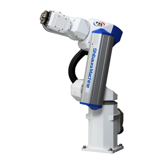
TRANSPORTATION AND INSTALLATION MANUAL 1.2. Name of Each Part Fig. 1.4 shows the name of each part of the robot of the TVL series. Axis 3 (rotation) Arm 2 (1) Axis 4 (rotation) Cable duct Axis 2 (rotation) Arm 2 (2) -
Page 15: External Dimensions
TRANSPORTATION AND INSTALLATION MANUAL 1.3. External Dimensions Fig. 1.5 to 1.6 refers to the external dimensions of the TVL500/TVL700. Dimensions used for cable (60) Fig. 1.5 External dimensions of the TVL500... - Page 16 TRANSPORTATION AND INSTALLATION MANUAL Dimensions used for cable (60) Fig. 1.6 External dimensions of the TVL700...
-
Page 17: Specifications Table
TRANSPORTATION AND INSTALLATION MANUAL 1.4. Specifications Table Item Specifications Remarks Structure Vertical multi-joint Model TVL500 TVL700 No. of controlled axes Total length 500(mm) 700(mm) Arm length Arm 1 260(mm) 400(mm) Arm 2 240(mm) 300(mm) Reach 602(mm) 801(mm) Axis 1 400(W) / 18.1(A Axis 2 400(W) / 18.1(A Axis 3... - Page 18 TRANSPORTATION AND INSTALLATION MANUAL Note 3: Repeatability in one direction at a constant ambient temperature of 20C Note 4: The color and surface treatment of the robot body may differ according to each production lot. Please note that there is no problem in the very nature of the product quality.
-
Page 19: Transportation
TRANSPORTATION AND INSTALLATION MANUAL 2. Transportation 2.1. Unpacking (for the TSL3100,TSL3100E) For the TS3100, please see 2.2, "Unpacking (for the TS3100)." The robot and controller are shipped separately in corrugated cardboards. Fig. 2.1 shows each packaging state. Open the packages in a location easily accessible, where the equipment is to be installed. - Page 20 DO NOT install and operate them. Otherwise, the equipment will malfunction. Contact Toshiba Machine immediately. • Dispose of the wooden pallet, corrugated cardboards, polyethylene shipping bags and cushion material according to the customer’s in-house regulations.
-
Page 21: Unpacking (For The Ts3100)
TRANSPORTATION AND INSTALLATION MANUAL 2.2. Unpacking (for the TS3100) For the TSL3100,TSL3100E, please see 2.1, "Unpacking (for the TSL3100,TSL3100E)" The robot and controller are shipped separately in corrugated cardboards. Fig. 2.2 shows each packaging state. Open the packages in a location easily accessible, where the equipment is to be installed. - Page 22 DO NOT install and operate them. Otherwise, the equipment will malfunction. Contact Toshiba Machine immediately. • Dispose of the wooden pallet, corrugated cardboards, polyethylene shipping bags and cushion material according to the customer’s in-house regulations.
-
Page 23: Transportation
TRANSPORTATION AND INSTALLATION MANUAL 2.3. Transportation Move the robot and controller very carefully. Make sure that no excessive impact or vibration is exerted on the equipment. If the equipment is to be subject to vibration over a long period, be sure to tighten all the clamp and base set bolts completely. If the equipment is to be moved to a location some distance from where it was unpacked, reposition the cushions as they were and put the equipment back into the corrugated cardboards. -
Page 24: Transporting The Robot
TRANSPORTATION AND INSTALLATION MANUAL Lifting jig Fixed jig Joint Angle (deg) Mass of robot body (including jigs shipped) 36 kg Fig. 2.4 Outer dimensions at transport 2.3.2. Transporting the Robot In principle, the robot should be transported in the state shown in Fig. 2.5 and 2.6 above. Fold back and secure the arm with the attached clamp. - Page 25 TRANSPORTATION AND INSTALLATION MANUAL Wire Fig. 2.5 Lifting up the robot (TVL500) CAUTION • The wire to be used should be such that can well withstand the mass of the robot. • When lifting up the robot, it may tilt a little. Lift it up slowly. •...
- Page 26 TRANSPORTATION AND INSTALLATION MANUAL DO NOT hold the arms 2 and 3. Handling areas Handling areas Fig. 2.6 Robot handling areas After the installation, remove the clamp and lifting jig used for transport. CAUTION • When lifting up the robot by workers, hold the locations (arrowed parts) by hands as shown in Fig.
-
Page 27: Transporting The Controller
TRANSPORTATION AND INSTALLATION MANUAL 2.3.3. Transporting the Controller Disconnect all cables and teach pendant before transporting the controller. DANGER • When placing the controller on the floor, etc., make sure not to have your hands or feet caught. 2.4. Storage Avoid storing the robot and controller for long periods of time after unpacking them. -
Page 28: Installation Of The Robot Body
0.98m/s or less Dust No inductive dust should exist. Consult with Toshiba Machine first if you wish to use the robot and controller in a dusty environment. No corrosive or combustible gas should exist. IP (Ingress IEC60529 IP40 (for the robot), and IP20 (for the controller) -
Page 29: Robot Installation
TRANSPORTATION AND INSTALLATION MANUAL DANGER • Do not place the robot or controller near combustible. Doing so could lead to fires if it ignites due to a fault, etc. CAUTION • If the robot is operated at high speed when started in a low-temperature environment, the torque increases, and an error can occur. - Page 30 TRANSPORTATION AND INSTALLATION MANUAL Fig. 3.1 External view TVL500...
- Page 31 TRANSPORTATION AND INSTALLATION MANUAL Fig. 3.2 External view TVL700...
-
Page 32: Working Envelope
TRANSPORTATION AND INSTALLATION MANUAL 3.2.2. Working Envelope Fig. 3.3 and 3.4 shows the working envelope of the robot. Each axis can operate within the working envelope. To prevent the robot from moving out of the working envelope by mis-operation, the robot is equipped with mechanical stoppers outside the working envelope. - Page 33 TRANSPORTATION AND INSTALLATION MANUAL Fig. 3.3 Working envelope TVL500...
- Page 34 TRANSPORTATION AND INSTALLATION MANUAL Fig. 3.4 Working envelope TVL700...
-
Page 35: Coordinate System
TRANSPORTATION AND INSTALLATION MANUAL 3.2.3. Coordinate System The robot's joint angle origin (0 position) is factory-calibrated according to the base reference planes. Fig. 3.5 shows the base coordinate system and origin of each axis joint angle. Axis 6 Axis 4 Axis 1 Axis 5 TVL500/TVL700... -
Page 36: Installing The Robot
TRANSPORTATION AND INSTALLATION MANUAL 3.2.4. Installing the Robot The robot is secured, using the set holes on the base (four (4) places). Use M10 hexagon socket head cap screws. The installation can be made in the following two steps. Select one of them according to your frame installation procedure. - Page 37 TRANSPORTATION AND INSTALLATION MANUAL [2] Step using the dowel pin Fig. 3.7 shows a robot installation step using the dowel pin. The bottom surface of the base is provided with a positioning dowel pin (6 mm). When you want to adjust the position of the base coordinate system of the base or to replace the robot, prepare a dowel pin hole on the frame on which to mount the robot.
-
Page 38: Working Envelope Change
TRANSPORTATION AND INSTALLATION MANUAL 3.3. Working Envelope Change This section explains the change of working envelope for the axes 1 to 3 of the TVL500/TVL700. CAUTION • If a working envelope is to be changed, design and manufacture mechanical stoppers in accordance with your operating conditions, referring to this manual. •... -
Page 39: Change Of Axis-1 Working Envelope
TRANSPORTATION AND INSTALLATION MANUAL 3.3.1. Change of Axis-1 Working Envelope <1> Change of axis-1 working envelope The TVL500/TVL700 is shipped while the soft limits and mechanical stoppers are factory-set for axis 1 to travel between 171. The first axis mechanical stopper is common to both the TVL500 and the TVL700 robots. - Page 40 TRANSPORTATION AND INSTALLATION MANUAL 2 x 6.8 drilling, Example of material: S45C Fig. 3.9 Factory-set mechanical stopper (TVL500/TVL700) 2 x M6 drilling, Fig. 3.10 Mechanical stopper location (at the base) (TVL500/TVL700)
- Page 41 TRANSPORTATION AND INSTALLATION MANUAL <2> Example of changing axis-1 working envelope and the change method Desired operating ranges of the machine can be set up by changing the shapes of the mechanical stoppers for the TVL500/TVL700 robot. To change the operating range of the first axis, the customer needs to design and produce a mechanical stopper by referring to Fig.
- Page 42 TRANSPORTATION AND INSTALLATION MANUAL Example of changing TVL500 axis-1 mechanical stopper Setting range: +90 to -120 2 x 6.8 drilling, Example of material: S45C Fig. 3.12 Example of changing axis-1 mechanical stoppers (reference)
-
Page 43: Change Of Axis-2 Working Envelope
TRANSPORTATION AND INSTALLATION MANUAL 3.3.2. Change of Axis-2 Working Envelope <1> Change of axis-2 working envelope W hen the TVL500/TVL700 robot is shipped from the factory, software limits and mechanical stoppers are preset so that the stroke of the second axis can satisfy the angles shown in Table 3.2. Table 3.2 Strokes of the second axis at factory shipment Operating direction TVL500... - Page 44 TRANSPORTATION AND INSTALLATION MANUAL Arm 1 center axis (axis 2 = 0) Working envelope (soft limit) Machine working envelope Mechanical stopper position on (mechanical stopper) the arm 1 side (for negative side soft limit) Factory-set soft limit -65 Machine working envelope Preset angle -65...
- Page 45 TRANSPORTATION AND INSTALLATION MANUAL Arm 1 center axis (axis 2 = 0) Working envelope (soft limit) Mechanical stopper position on Machine working envelope the arm 1 side (for negative side (mechanical stopper) soft limit) Factory-set soft limit -91 Machine working envelope Base swivel Preset angle -91...
- Page 46 TRANSPORTATION AND INSTALLATION MANUAL Example of changing movable range (TVL500) Setting range: +90, -30 Working envelope (soft limit) Arm 1 center axis (axis 2 = 0) Machine working envelope (mechanical stopper) Mechanical stopper position on the arm 1 side (for negative side soft limit) Soft limit setting -30...
- Page 47 TRANSPORTATION AND INSTALLATION MANUAL Arm 1 center position 4 x 4.3 drilling, from rear side * This cannot be changed by the customer. Example of material: S45C Fig. 3.16 Arm 1 side mechanical stopper (TVL500) 4 x 4.3 drilling, 4.3 from rear side Arm 1 center position * This cannot be changed by the customer.
- Page 48 TRANSPORTATION AND INSTALLATION MANUAL Example of changing movable range Setting range: -30, -90 4 x 5.5 drilling * This cannot be changed by the customer. Example of material: S45C Fig. 3.18 Design example of mechanical stopper on base swivel side (For reference, e.g.: TVL 500)
-
Page 49: Change Of Axis-3 Working Envelope
TRANSPORTATION AND INSTALLATION MANUAL 3.3.3. Change of Axis-3 Working Envelope <1> Before shipment of the TVL 500/TVL700, the soft limit and mechanical stopper are set in such a way that the stroke of the axis 3 is kept within the range of Table 3.3. - Page 50 TRANSPORTATION AND INSTALLATION MANUAL Working envelope (soft limit) Arm 2 (2) center axis (axis 3 = 0) Factory-set soft limit -0.5 Machine working envelope (mechanical stopper) Machine working envelope Preset angle -0.5 + Mechanical stopper position on the arm 1 side (for negative side soft limit) Mechanical stopper position on the arm 1 side (for positive side...
- Page 51 TRANSPORTATION AND INSTALLATION MANUAL Working envelope (soft limit) Arm 2 center axis (axis 3 = 0) Factory-set soft limit -0.5 Machine working envelope (mechanical stopper) Machine working envelope (Mechanical stopper preset angle) -0.5 + Mechanical stopper position on the arm 1 side (for negative side soft limit) Mechanical stopper position on the arm 1 side...
- Page 52 TRANSPORTATION AND INSTALLATION MANUAL Arm 2 center axis (axis 3 = 0) Example of changing movable range Setting range: +90º, -30º Working envelope (soft Factory-set soft limit -0.5 limit) Machine working envelope (Mechanical stopper preset angle) -0.5 + Machine working envelope (mechanical stopper) Mechanical stopper position on the arm 1 side (for positive side...
- Page 53 TRANSPORTATION AND INSTALLATION MANUAL 3x3.3 drilling, from rear side * This cannot be changed by the customer. Example of material: S45C Fig. 3.22 Arm 1 side mechanical stopper (TVL500) 3x3.3 drilling, from rear side * This cannot be changed by the customer.
-
Page 54: Precautions For Handling The Teach Pendant
TRANSPORTATION AND INSTALLATION MANUAL Example of changing movable range Setting range: -0, -90 * This cannot be changed by the customer. Example of material: S45C Fig. 3.24 Design example of mechanical stopper on the arm 2 (1) side (For reference, e.x. TVL500) 3.4. -
Page 55: Installing The Controller(In Case Of Tsl3100)
TRANSPORTATION AND INSTALLATION MANUAL 4. Installing the Controller(In case of TSL3100) 4.1. External Dimensions For the TSL3100E, please see "5. Installation of the Controller (In case of TSL3100E)". For the TS3100, please see "6. Installation of the Controller (In case of TS3100)". External view of the controller is shown in Fig. -
Page 56: Precautions For Direct Installation
TRANSPORTATION AND INSTALLATION MANUAL 4.2. Precautions for Direct Installation It is necessary to provide a clearance of 50 mm or more in the horizontal direction and a clearance of 100 mm or more in the upward direction near the controller. CAUTION •... -
Page 57: Installation Surface Dimensions
TRANSPORTATION AND INSTALLATION MANUAL 4.3. Installation surface dimensions To install the robot controller TSL3100 on the control panel or others, mount the fixture using the rubber leg screw hole on the bottom surface, and fix the controller on the control panel. Note) The fixture (two-piece set) is optional. -
Page 58: Cautions For Assembling The Control Panel
TRANSPORTATION AND INSTALLATION MANUAL 4.4. Cautions for assembling the control panel To install the robot controller TSL3100 on the control panel or others, take care of the following: a) To install the robot controller TSL3100 on the control panel or others, remove the rubber leg from on the bottom surface. - Page 59 TRANSPORTATION AND INSTALLATION MANUAL Fig. 4.4 Removing upper cover (TSL3100)
- Page 60 TRANSPORTATION AND INSTALLATION MANUAL e) For connection with the robot cable connector, a clearance of 122 mm must be provided on the front portion of the controller, and a clearance of 110 mm on the rear of the controller. * Compatibility with Ethernet or distributed I/O provided Fig.
-
Page 61: Installing The Controller (In Case Of Tsl3100E)
TRANSPORTATION AND INSTALLATION MANUAL 5. Installing the Controller (In case of TSL3100E) 5.1. External Dimensions For the TSL3100, please see "4. Installation of the Controller (In case of TSL3100)." For the TS3100, please see "6. Installation of the Controller (In case of TS3100)." External view of the controller is shown in Fig. -
Page 62: Precautions For Direct Installation
TRANSPORTATION AND INSTALLATION MANUAL 5.2. Precautions for Direct Installation It is necessary to provide a clearance of 50 mm or more in the horizontal direction and a clearance of 100 mm or more in the upward direction near the controller. CAUTION •... -
Page 63: Installation Surface Dimensions
TRANSPORTATION AND INSTALLATION MANUAL 5.3. Installation surface dimensions To install the robot controller TSL3100E on the control panel or others, mount the fixture using the rubber leg screw hole on the bottom surface, and fix the controller on the control panel. The rubber leg located in the middle of controller should not be removed Note) The fixture (two-piece set) is optional. -
Page 64: Cautions For Assembling The Control Panel
TRANSPORTATION AND INSTALLATION MANUAL 5.4. Cautions for assembling the control panel To install the robot controller TSL3100E on the control panel or others, take care of the following: a) To install the robot controller TSL3100E on the control panel or others, remove the rubber leg from on the bottom surface. - Page 65 TRANSPORTATION AND INSTALLATION MANUAL d) For connection with the robot cable connector, a clearance of 122 mm must be provided on the front portion of the controller, and a clearance of 110 mm on the rear of the controller. Fig. 5.5 Clearance of controller front side (TSL3100E) CAUTION •...
-
Page 66: Installing The Controller (In Case Of Ts3100)
TRANSPORTATION AND INSTALLATION MANUAL 6. Installing the Controller (In case of TS3100) 6.1. External Dimensions For the TSL3100, please see "4. Installation of the Controller (In case of TSL3100)." For the TSL3100E, please see "5. Installation of the Controller (In case of TSL3100E)." External view of the controller is shown in Fig. -
Page 67: Precautions For Direct Installation
TRANSPORTATION AND INSTALLATION MANUAL 6.2. Precautions for Direct Installation It is necessary to provide a clearance of 50 mm or more in the horizontal direction and a clearance of 100 mm or more in the upward direction near the controller. CAUTION •... -
Page 68: Installation Surface Dimensions
TRANSPORTATION AND INSTALLATION MANUAL 6.3. Installation surface dimensions When installing the robot controller by mounting in a rack, use the holes located at both ends of the front panel to fix the robot controller to the rack. The side bracket [1] in Fig. 6.3 is an option. - Page 69 TRANSPORTATION AND INSTALLATION MANUAL b) Because a cable connector will be connected to the rear of the robot controller, a space of at least 110 mm is necessary in the rear direction. To perform maintenance of the robot controller, remove the upper cover. (See Fig. 6.4.) When installing the robot controller, make sure that the maintenance of the robot controller can be done without any problem.
- Page 70 TRANSPORTATION AND INSTALLATION MANUAL c) When mounting the robot controller in a rack, be sure to construct so that the weight of the robot controller can be supported by the legs of the robot controller themselves. The robot controller's rack mount screw holes are provided to fasten the robot controller panel and thus the weight of the robot controller cannot be supported solely with these.
-
Page 71: System Connections(In Case Of Tsl3100)
TRANSPORTATION AND INSTALLATION MANUAL 7. System Connections(In case of TSL3100) 7.1. Cable Wiring This section describes the various types of cables and connectors and explains how these are to be connected. 7.1.1. Connector Arrangement on the Controller The cables connected to the robot controller are shown in Fig. 6.1. Fig. -
Page 72: Connecting The Power Cable "Acin
TRANSPORTATION AND INSTALLATION MANUAL [4] Brake signal cable (BRK) [5] External operation input signal cables (INPUT, OUTPUT) [6] Power supply cable for external input/output (GND, P24V) In the subsequent paragraphs, we explain how to connect cables [1] to [4] inclusive. For information on how to connect cables [5] and [6] refer to the Interface Manual. - Page 73 TRANSPORTATION AND INSTALLATION MANUAL DANGER • Be sure to use the designated wire. Failure to do so could lead to fires or faults. • When connecting the connector and wires, make sure not to mistake the terminal arrangement. • After making the connection, use a tester, etc., to confirm the connection. CAUTION •...
-
Page 74: Connecting The Motor Cable/Encoder Cable
TRANSPORTATION AND INSTALLATION MANUAL 7.1.3. Connecting the Motor Cable/Encoder Cable The motor cable connects the controller and robot, and supplies the power required to rotate the motor from the controller servo driver to each axis feed motor of the robot. The encoder cable is a signal line used to transmit a signal from the rotation angle detecting encoder of each robot axis to the controller. -
Page 75: Connecting The Brake Cable/Robot Control Signal Cable
TRANSPORTATION AND INSTALLATION MANUAL 7.1.4. Connecting the Brake Cable/Robot Control Signal Cable The brake cable is used to input and output an ON/OFF signal for the brake to lock the motor shaft. The brake signal cable used to lock the motor shaft is connected to the connector BRK ([4] in Fig. -
Page 76: Connecting And Disconnecting Cables
TRANSPORTATION AND INSTALLATION MANUAL CAUTION Be sure to supply external power (24 DVC). Otherwise, the safety signal will not be enabled and the controller servo power cannot be turned on. 7.1.6. Connecting and Disconnecting Cables CAUTION • Before connecting or disconnecting any controller cable, be sure to turn off the main power. - Page 77 TRANSPORTATION AND INSTALLATION MANUAL Connector lever Fig. 7.3 Connecting and disconnecting a ROBOT connector(TSL3100) b) Square connectors: INPUT, OUTPUT, TP, HOST/TCPRG, COM1, BRK, HAND Firstly, completely insert the cable side connector into the controller connector. Then tighten the lock screws on both ends of the cable side connector with a screwdriver.
-
Page 78: Examples Of Connector Terminal Arrangement (For The Tsl3100)
TRANSPORTATION AND INSTALLATION MANUAL Controller side connector Cable side connector Connector Tighten. Loosen. Fig. 7.4 Connecting and disconnecting a square connector (TSL3100) 7.1.7. Examples of Connector Terminal Arrangement (for the TSL3100) a) Power cable connector ACIN Connects to controller. Type: 03JFAT-SAYGF-I Manufacturer: J.S.T. - Page 79 TRANSPORTATION AND INSTALLATION MANUAL b) Motor/Encoder cable connector ROBOT Connects to controller. Manufacturer: Harting Co., Ltd. For encoder For motor power c) General purpose input signal cable connector INPUT Connects to controller. Type: XM3B-3722-112 Manufacturer: Omron The counterpart is attached to the controller. For details, see Part ST85364 TSL3000 Interface.
- Page 80 TRANSPORTATION AND INSTALLATION MANUAL e) Input/output signal power supply connector Connects to controller. Type: ML-4000-CWJH 02PGY Manufacturer: Sato Parts Co., Ltd. The counterpart is attached to the controller. For details, see Part ST85364 TSL3000 Interface. Communication connector HOST/TCPRG,COM1 Connects to controller. Type: XM2C-0942-132L Manufacturer:...
- Page 81 TRANSPORTATION AND INSTALLATION MANUAL k) Brake signal cable connector BRK Connects to controller. Type: J21DPM-12V-KX Manufacturer: J.S.T. Mfg. Robot control signal cable connector HAND Connects to controller. Type: J21DPM-20V-KX Manufacturer: J.S.T. Mfg.
-
Page 82: Controller Connector Signals
TRANSPORTATION AND INSTALLATION MANUAL 7.2. Controller Connector Signals 7.2.1. Connector Signal Connection Diagrams Diagrams showing which signals correspond to which terminals are shown in Section 2 of the Interface Manual. 7.2.2. Jumpers for Safety Related Signals The following system input signals are provided to serve for the safety purpose. System input signals... - Page 83 TRANSPORTATION AND INSTALLATION MANUAL CAUTION • Unless the signals of SVOFF and emergency stop contacts 1, 2 are jumpered, the controller servo power cannot be turned on. • Unless the CYCLE signal is jumpered, the controller enters the cycle operation mode.
-
Page 84: System Connections (In Case Of Tsl3100E)
TRANSPORTATION AND INSTALLATION MANUAL 8. System Connections (In case of TSL3100E) 8.1. Cable Wiring This section describes the various types of cables and connectors and explains how these are to be connected. 8.1.1. Connector Arrangement on the Controller The cables connected to the robot controller are shown in Fig. 8.1. Fig. -
Page 85: Connecting The Power Cable "Acin
TRANSPORTATION AND INSTALLATION MANUAL [4] Brake signal cable (BRK) [5] External operation input signal cables (INPUT, OUTPUT) [6] Power supply cable for external input/output (GND, P24V) In the subsequent paragraphs, we explain how to connect cables [1] to [4] inclusive. For information on how to connect cables [5] and [6] refer to the Interface Manual. - Page 86 TRANSPORTATION AND INSTALLATION MANUAL DANGER • Be sure to use the designated wire. Failure to do so could lead to fires or faults. • When connecting the connector and wires, make sure not to mistake the terminal arrangement. • After making the connection, use a tester, etc., to confirm the connection. CAUTION •...
-
Page 87: Connecting The Motor Cable/Encoder Cable
TRANSPORTATION AND INSTALLATION MANUAL 8.1.3. Connecting the Motor Cable/Encoder Cable The motor cable connects the controller and robot, and supplies the power required to rotate the motor from the controller servo driver to each axis feed motor of the robot. The encoder cable is a signal line used to transmit a signal from the rotation angle detecting encoder of each robot axis to the controller. -
Page 88: Connecting The Brake Cable/Robot Control Signal Cable
TRANSPORTATION AND INSTALLATION MANUAL 8.1.4. Connecting the Brake Cable/Robot Control Signal Cable The brake cable is used to input and output an ON/OFF signal for the brake to lock the motor shaft. The brake signal cable used to lock the motor shaft is connected to the connector BRK ([4] in Fig. -
Page 89: Connecting And Disconnecting Cables
TRANSPORTATION AND INSTALLATION MANUAL See the "Instruction Manual: Interface" for how to connect/disconnect the power supply cable for external input/output. CAUTION Be sure to supply external power (24 DVC). Otherwise, the safety signal will not be enabled and the controller servo power cannot be turned on. 8.1.6. - Page 90 TRANSPORTATION AND INSTALLATION MANUAL Connector lever Fig. 8.3 Connecting and disconnecting a ROBOT connector(TSL3100E) b) Square connectors: INPUT, OUTPUT, TP, HOST/TCPRG, COM1, BRK, HAND Firstly, completely insert the cable side connector into the controller connector. Then tighten the lock screws on both ends of the cable side connector with a screwdriver.
- Page 91 TRANSPORTATION AND INSTALLATION MANUAL Controller side connector Cable side connector Connector Tighten. Loosen. Fig. 8.4 Connecting and disconnecting a square connector (TSL3100E) c) Circular connector: ACIN To connect the connector, align the key position, securely insert the connector on the cable side into the connector on the robot controller body side, and then tighten by rotating the lock screw on the cable side clockwise.
-
Page 92: Examples Of Connector Terminal Arrangement (For The Tsl3100)
TRANSPORTATION AND INSTALLATION MANUAL 8.1.7. Examples of Connector Terminal Arrangement (for the TSL3100) a) Power cable connector ACIN Connects to controller. Type: JL04V-2E18-10PE-B Manufacturer: J.S.T. Msg. Single-phase, 190 to 240 VAC, 50/60 Hz Grounding (Class D or higher level) DANGER •... - Page 93 TRANSPORTATION AND INSTALLATION MANUAL c) General purpose input signal cable connector INPUT Connects to controller. Type: XM3B-3722-112 Manufacturer: Omron The counterpart is attached to the controller. For details, see Part ST85364 TSL3000 Interface or Part ST85457 TSL3000E Interface. d) General purpose output signal cable connector OUTPUT Connects to controller.
- Page 94 TRANSPORTATION AND INSTALLATION MANUAL g) Ethernet connector LAN (Controller rear) Connects to controller. Type: J0026D21BNL Manufacturer: PULSE Electronics Brake signal cable connector BRK Connects to controller. Type: J21DPM-12V-KX Manufacturer: J.S.T. Mfg. Robot control signal cable connector HAND Connects to controller. Type: J21DPM-20V-KX Manufacturer:...
-
Page 95: Controller Connector Signals
TRANSPORTATION AND INSTALLATION MANUAL 8.2. Controller Connector Signals 8.2.1. Connector Signal Connection Diagrams Diagrams showing which signals correspond to which terminals are shown in Section 2 of the Interface Manual. 8.2.2. Jumpers for Safety Related Signals The following system input signals are provided to serve for the safety purpose. System input signals... - Page 96 TRANSPORTATION AND INSTALLATION MANUAL CAUTION • Unless the signals of SVOFF and emergency stop contacts 1, 2 are jumpered, the controller servo power cannot be turned on. • Unless the CYCLE signal is jumpered, the controller enters the cycle operation mode.
-
Page 97: System Connections(In Case Of Ts3100)
TRANSPORTATION AND INSTALLATION MANUAL 9. System Connections(In case of TS3100) 9.1. Cable Wiring This section describes the various types of cables and connectors and explains how these are to be connected. 9.1.1. Connector Arrangement on the Controller The cables connected to the robot controller are shown in Fig. 9.1. Fig. -
Page 98: Connecting The Power Cable "Acin
TRANSPORTATION AND INSTALLATION MANUAL 9.1.2. Connecting the Power Cable The power cable “ACIN” ([1] of Fig. 9.1) is used to supply the main AC power to the controller. Table 9.1 Power supply specifications (TS3100) Power supply Single-phase, 200~240V, 50/60H ±1H Instantaneous Within 40 msec power failure... -
Page 99: Connecting The Motor Cable/Encoder Cable
TRANSPORTATION AND INSTALLATION MANUAL 9.1.3. Connecting the Motor Cable/Encoder Cable The motor cable connects the controller and robot, and supplies the power required to rotate the motor from the controller servo driver to each axis feed motor of the robot. The encoder cable is a signal line used to transmit a signal from the rotation angle detecting encoder of each robot axis to the controller. -
Page 100: Connecting Power Supply Cable For External Input/Output "Gnd, P24V
TRANSPORTATION AND INSTALLATION MANUAL The robot control signal cable is used for input and output of robot control signals such as hand operation signal. The robot control signal cable is connected to the connector "HAND" ([4] of Fig. 9.1). The brake cable/robot control signal cable on the robot side are connected to [2] of Fig. 9.2. - Page 101 TRANSPORTATION AND INSTALLATION MANUAL The wires for the “EMS” connector are AWG24 to AWG16. Choose the most suitable external power supply for your system specification (ampacity) For details about the plugging and unplugging the "EMS" connector, see the "Instruction Manual: Interface." CAUTION Be sure to supply external power (24 DVC).
-
Page 102: Connecting And Disconnecting Cables
TRANSPORTATION AND INSTALLATION MANUAL 9.1.6. Connecting and Disconnecting Cables CAUTION • Before connecting or disconnecting the cables to or from the robot controller, be sure to turn off the main power (POWER switch) in advance. • When disconnecting a cable, be sure to pull the connector and not the cord. Otherwise, you may damage the cable. - Page 103 TRANSPORTATION AND INSTALLATION MANUAL b) Square connectors: ENC, HAND, SYSTEM, INPUT, OUTPUT, TRIG, CONF. Firstly, completely insert the cable side connector into the controller connector. Then tighten the lock screws on both ends of the cable side connector with a screwdriver.
-
Page 104: Examples Of Connector Terminal Arrangement (For The Ts3100)
TRANSPORTATION AND INSTALLATION MANUAL 9.1.7. Examples of Connector Terminal Arrangement (for the TS3100) a) Power cable connector ACIN Connects to controller. Model:JL04HV-2E22-22PE-B Manufacturer: Japan Aviation Electronics Industry, Limited Danger Single-phase, 200 to 240V AC,50/60Hz ● Completely connect the grounding cable. Otherwise, an electric shock or fire may be caused if a fault or electric leak Grounding (Class D or higher level) - Page 105 TRANSPORTATION AND INSTALLATION MANUAL b) Motor cable connector MOTOR Connects to controller. Type: JL04V-2A28-11SE Manufacturer: Japan Aviation Electronics Industry, Ltd c) Encoder cable connector ENC Connects to controller. 17 16 15 14 13 12 11 Type: 52986-3659 28 27 26 25 24 23 22 21 20 19 36 35 34 33 32 31 30 29 Manufacturer: Molex Co., Ltd.
- Page 106 TRANSPORTATION AND INSTALLATION MANUAL h) Trigger input connector TRIG Connects to controller. Type: XM2C-1542-112L 9 10 Manufacturer: Omron Encoder cable connector CONV Connects to controller. Type: 52986-1479 14 13 12 11 10 9 8 Manufacturer: Molex Co., Ltd. Emergency stop, safety input and external P24V supply connector EMS Connects to controller.
-
Page 107: Controller Connector Signals (For The Ts3100)
TRANSPORTATION AND INSTALLATION MANUAL 9.2. Controller Connector Signals (for the TS3100) 9.2.1. Connector Signal Connection Diagrams Diagrams showing which signals correspond to which terminals are shown in Section 2 of the Interface Manual. 9.2.2. Jumpers for Safety Related Signals The following system input signals are provided to serve for the safety purpose. System input signals... - Page 108 TRANSPORTATION AND INSTALLATION MANUAL CAUTION • Unless the signals of SVOFF and emergency stop contacts 1, 2 are jumpered, the controller servo power cannot be turned on. • Unless the CYCLE signal is jumpered, the controller enters the cycle operation mode.
-
Page 109: When Detaching The Control Panel From The Controller (For The Ts3100)
TRANSPORTATION AND INSTALLATION MANUAL 9.3. When Detaching the Control Panel from the Controller (for the TS3100) 9.3.1. Dismounting the Control Panel To dismount the control panel, perform the following procedure. a) Loosen the four corner screws that fix the control panel. b) Remove the four screws and slowly pull out the panel section forward. -
Page 110: Installation Dimensions Of The Control Panel
TRANSPORTATION AND INSTALLATION MANUAL 9.3.3. Installation Dimensions of the Control Panel The installation dimensions of the control panel are as shown in Fig. 9.6. Cross truss screws (φ3×6, ZN3-B) are used. 4-M3 Fig. 9.7 Installation dimensions of the control panel (TS3100) -
Page 111: Mounting The Dummy Panel To The Controller
TRANSPORTATION AND INSTALLATION MANUAL 9.3.4. Mounting the Dummy Panel to the Controller After the control panel is dismounted from the controller, mount the dummy panel to the location where there was the control panel as shown in Fig. 9.8. The dummy panel and mounting parts are provided as options. -
Page 112: Dimensions When The Control Panel Is Detached
TRANSPORTATION AND INSTALLATION MANUAL 9.3.5. Dimensions When the Control Panel Is Detached The connection diagram of the control panel and the dummy panel is shown in Fig. 9.9. Allocate a clearance of 50 mm or more (60 mm or more when the cover is used) in the back of the detached control panel. -
Page 113: Tool Interface (Robot Body Side)
TRANSPORTATION AND INSTALLATION MANUAL 10. Tool Interface (Robot Body Side) 10.1. Mounting Tool The tool is to be mounted on the tool mounting flange at the end of arm 3. Fig. 10.1 shows the dimensions of the tool mounting flange. As shown in Fig. -
Page 114: Tool Air Piping
TRANSPORTATION AND INSTALLATION MANUAL 10.2. Tool Air Piping The robot is provided with four (4) air lines for the tool. The outer diameter of the air pipelines is 4 mm. Fig. 10.2 shows the tool air piping. Enlarged view of hand panel 4 x 4 (dia) air tube (one-touch type) 4 x 4 (dia) air tube... - Page 115 TRANSPORTATION AND INSTALLATION MANUAL Hand IO option HAND IO connector Fig. 10.3 Tool air piping (option)
-
Page 116: Permissible Load Conditions And Program Setting
TRANSPORTATION AND INSTALLATION MANUAL 10.3. Permissible Load Conditions and Program Setting This paragraph describes the permissible load conditions of the robot and how to set up the program according to the load. 10.3.1. Permissible Load Conditions The robot load conditions are defined by the tool mass, moment of inertia and offset value of tool gravity center from the center of the tool shaft, as shown in Fig. - Page 117 TRANSPORTATION AND INSTALLATION MANUAL CAUTION • NEVER operate the robot under the load conditions exceeding the permissible values. Otherwise, the robot life and safety cannot be guaranteed. Inertia moment The following drawing shows an example of a model with simplified robot and load, and a formula for calculating the load inertia moment.
-
Page 118: Load Conditions And Program Setting
TRANSPORTATION AND INSTALLATION MANUAL 10.3.2. Load Conditions and Program Setting This robot can automatically change the maximum speed, acceleration/deceleration and servo gain by using the PAYLOAD command in the program according to the load conditions. Be sure to use the PAYLOAD command. The specific method for using this function is explained below. - Page 119 TRANSPORTATION AND INSTALLATION MANUAL (Program example 2) When the hand mass is 3 kg and the gravity center offset is (0 mm, 0 mm, 20 mm) and the mass is 1 kg and gravity center offset is (30 mm, 0 mm, 50 mm) when the workpiece is grasped.
- Page 120 TRANSPORTATION AND INSTALLATION MANUAL c) Setting of PAYLOAD command In the default state, or when the PAYLOAD command is not used, the maximum speed and acceleration/deceleration are set to 100 % and the servo gain is set to the value under the minimum load. (See Para. 8.3.3.) CAUTION •...
-
Page 121: Tool Interface (For The Tsl 3100)
TRANSPORTATION AND INSTALLATION MANUAL 11. Tool Interface (for the TSL 3100) 11.1. Tool wiring The robot is provided with the tool cable air pipe and arm 1 (1) (arm 2 (2) and arm 3 as options). Connection to external equipment from the robot controller can also be made without using the tool wiring in the robot arm. - Page 122 TRANSPORTATION AND INSTALLATION MANUAL a-2) Input signal connector HAND (TSL3100 Type-P) Signal name Signal No. Input circuit and example of connections D_IN1 Input signal 1 Customer’s side TSL3100 D_IN2 Input signal 2 INPUTCOM D_IN3 Input signal 3 D_IN4 Input signal 4 ●...
- Page 123 TRANSPORTATION AND INSTALLATION MANUAL b-1) Output signal connector HAND (TSL3100 Type-N) Signal name Signal No. Output circuit and example of connections D_OUT1 Output signal 1 Customer’s side D_OUT2 Output signal 2 P24V DC relay ● D_OUT3 Output signal 3 ● D_OUT4 Output signal 4 ●...
- Page 124 TRANSPORTATION AND INSTALLATION MANUAL b-2) Output signal connector HAND (TSL3100 Type-P) Signal name Signal No. Output circuit and example of connections D_OUT1 Output signal 1 Customer’s side D_OUT2 Output signal 2 P24V ● D_OUT3 Output signal 3 DC relay D_OUT4 Output signal 4 ●...
-
Page 125: Tool Wiring (Robot Arm Side)
TRANSPORTATION AND INSTALLATION MANUAL 11.1.2. Tool Wiring (Robot Arm Side) Four input signals are provided for sensors, etc. and four control signals for solenoid valves, etc. A supply power signal of 24 VDC is also provided. They are connected to the controller. - Page 126 TRANSPORTATION AND INSTALLATION MANUAL Type of contact: SHF-001T-0.8BS Adaptive cable: AWG22~AWG28 HOUT Grommet inner dia. 15 mm Cable inlet (1 places) Fig. 11.1. Wiring to PLC, etc. Mechanical side Input/output signal connector HAND (TSL 3100 Type-N) Signal name Signal No. Input/output circuit and example of connections Input signal 1 D_IN1...
- Page 127 TRANSPORTATION AND INSTALLATION MANUAL Input/output signal connector HOUT3, HOUT4 (TSL3100 Type-N) (This connector is located in arm 2 (1), and connected to the solenoid valve when the manifold is optional.) Pin (Connector): HOUT3) Signal name Signal No. D_OUT5 Output signal 5 D_OUT6 Output signal 6 DC 24V (P24V)
- Page 128 TRANSPORTATION AND INSTALLATION MANUAL Input/output signal connector HAND (TSL3100 Type-P) Signal name Signal No. Input/output circuit and example of connections Input signal 1 Customer’s side Arm 2 (1) TS3100 D_IN1 Input Input signal 2 D_IN2 P24V Input signal 3 D_IN3 Input signal 4 D_IN4 ●...
- Page 129 TRANSPORTATION AND INSTALLATION MANUAL As input signals, no-voltage contacts or transistor open collector inputs are used. No-voltage contact specifications: Contact rating: 24 VDC, 10 mA or over (circuit current: approx. 7 mA) Minimum contact current: 24 VDC, 1 mA 100 or less Contact impedance: Transistor specifications: Withhold voltage between collector and emitter: 30 V or over...
- Page 130 TRANSPORTATION AND INSTALLATION MANUAL Table 11.1 HAND cable (option) list Part name Toshiba Dwg. No. Unit code Maker Plug type Length 392N1201 Y610A3VP0 Toshiba Angle plug I/O cable Machine 392N1202 Y610A3VQ0 HAND/IO connector Inside arm 2 (1) (standard) Inside arm 3 (optional)
- Page 131 TRANSPORTATION AND INSTALLATION MANUAL Common to types N and P For solenoid valve (optional) For hand IO installation position change (optional) Fig. 11.3 Internal connection diagram (TSL3100)
-
Page 132: Tool Interface (For The Tsl3100E)
TRANSPORTATION AND INSTALLATION MANUAL 12. Tool Interface (for the TSL3100E) 12.1. Tool wiring The robot is provided with the tool cable air pipe and arm 1 (1) (arm 2 (2) and arm 3 as options). Connection to external equipment from the robot controller can also be made without using the tool wiring in the robot arm. - Page 133 TRANSPORTATION AND INSTALLATION MANUAL a-2) Input signal connector HAND (TSL3100E Type-P) Signal name Signal No. Input circuit and example of connections Customer side TSL3100E お 客様側 D_IN1 Input signal 1 P24V D_IN2 Input signal 2 D_IN3 Input signal 3 ● D_IN4 Input signal 4 Contact or...
- Page 134 TRANSPORTATION AND INSTALLATION MANUAL b-1) Output signal connector HAND (TSL3100E Type-N) Signal name Signal No. Output circuit and example of connections Customer side お 客様側 D_OUT1 Output signal 1 【P24G(-) コモン 接続】 P24V [P24G( - )common connection] ● D_OUT2 Output signal 2 SYSOUTCOM ●...
- Page 135 TRANSPORTATION AND INSTALLATION MANUAL b-2) Output signal connector HAND (TSL3100E Type-P) Signal name Signal No. Output circuit and example of connections D_OUT1 Output signal 1 Customer side お 客様側 【P24V(+)コモン 接続】 [P24G( + )common connection] P24V ● D_OUT2 Output signal 2 SYSOUTCOM ●...
-
Page 136: Tool Wiring (Robot Arm Side)
TRANSPORTATION AND INSTALLATION MANUAL 12.1.2. Tool Wiring (Robot Arm Side) Four input signals are provided for sensors, etc. and four control signals for solenoid valves, etc. A supply power signal of 24 VDC is also provided. They are connected to the controller. - Page 137 TRANSPORTATION AND INSTALLATION MANUAL Type of contact: SHF-001T-0.8BS Adaptive cable: AWG22~AWG28 HOUT Grommet inner dia. 15 mm Cable inlet (1 places) Fig. 12.1. Wiring to PLC, etc. Mechanical side Input/output signal connector HAND (TSL3100E Type-N) Signal name Signal No. Input/output circuit and example of connections Arm 2 (1) TSL3100E お...
- Page 138 TRANSPORTATION AND INSTALLATION MANUAL Input/output signal connector HOUT3, HOUT4 (TSL3100E Type-N) (This connector is located in arm 2 (1), and connected to the solenoid valve when the manifold is optional.) Pin (Connector): HOUT3) Signal name Signal No. D_OUT5 Output signal 5 D_OUT6 Output signal 6 D C 2 4 V ( P 2 4 V )
- Page 139 TRANSPORTATION AND INSTALLATION MANUAL Input/output signal connector HAND (TSL3100E Type-P) Signal name Signal No. Input/output circuit and example of connections Input signal 1 D_IN1 Input Arm 2 (1) Input signal 2 D_IN2 Customer’s side TSL3100E TS3100 Input signal 3 D_IN3 P24V Input signal 4 D_IN4...
- Page 140 TRANSPORTATION AND INSTALLATION MANUAL As input signals, no-voltage contacts or transistor open collector inputs are used. No-voltage contact specifications: Contact rating: 24 VDC, 10 mA or over (circuit current: approx. 7 mA) Minimum contact current: 24 VDC, 1 mA 100 or less Contact impedance: Transistor specifications: Withhold voltage between collector and emitter: 30 V or over...
- Page 141 TRANSPORTATION AND INSTALLATION MANUAL Table 12.1 HAND cable (option) list Part name Toshiba Dwg. No. Unit code Maker Plug type Length 392N1201 Y610A3VP0 Toshiba Angle plug I/O cable Machine 392N1202 Y610A3VQ0 HAND/IO connector Inside arm 2 (1) (standard) Inside arm 3 (optional)
- Page 142 TRANSPORTATION AND INSTALLATION MANUAL Common to types N and P For solenoid valve (optional) For hand IO installation position change (optional) Fig. 12.3 Internal connection diagram (TSL3100)
-
Page 143: Tool Interface (For The Ts3100)
TRANSPORTATION AND INSTALLATION MANUAL 13. Tool Interface (for the TS3100) 13.1. Tool wiring The robot is provided with the tool cable air pipe and arm 1 (1) (arm 2 (2) and arm 3 as options). Connection to external equipment from the robot controller can also be made without using the tool wiring in the robot arm. - Page 144 TRANSPORTATION AND INSTALLATION MANUAL a-2) Input signal connector HAND (TS3100 Type-P) Signal name Signal No. Input circuit and example of connections D_IN1 Input signal 1 Customer’s side TS3100 D_IN2 Input signal 2 P24V D_IN3 Input signal 3 D_IN4 Input signal 4 ●...
- Page 145 TRANSPORTATION AND INSTALLATION MANUAL b-1) Output signal connector HAND (TS3100 Type-N) Signal name Signal No. D_OUT1 Output signal 1 Customer’s side D_OUT2 Output signal 2 P24V DC relay ● D_OUT3 Output signal 3 ● D_OUT4 Output signal 4 ● D_OUT5 Output signal 5 Diode for preventing counter electromotive voltage...
- Page 146 TRANSPORTATION AND INSTALLATION MANUAL b-2) Output signal connector HAND (TS3100 Type-P) Signal name Signal No. Output circuit and example of connections D_OUT1 Output signal 1 Customer’s side D_OUT2 Output signal 2 P24V ● D_OUT3 Output signal 3 DC relay D_OUT4 Output signal 4 ●...
- Page 147 TRANSPORTATION AND INSTALLATION MANUAL 13.1.2. Tool Wiring (Robot Arm Side) Four input signals are provided for sensors, etc. and four control signals for solenoid valves, etc. A supply power signal of 24 VDC is also provided. They are connected to the controller.
- Page 148 TRANSPORTATION AND INSTALLATION MANUAL Type of contact: SHF-001T-0.8BS Adaptive cable: AWG22~AWG28 HOUT Grommet inner dia. 15 mm Cable inlet (1 places) Fig. 13.1. Wiring to PLC, etc.
- Page 149 TRANSPORTATION AND INSTALLATION MANUAL Mechanical side Input/output signal connector HAND (Type-N) Signal name Signal No. Input/output circuit and example of connections Input signal 1 D_IN1 Input Customer’s side TS3100 Arm 2 (1) Input signal 2 D_IN2 P24V ● Input signal 3 D_IN3 ●...
- Page 150 TRANSPORTATION AND INSTALLATION MANUAL Input/output signal connector HOUT3, HOUT4 (Type-N) (This connector is located in arm 2 (1), and connected to the solenoid valve when the manifold is optional.) Pin (Connector): HOUT3) Signal name Signal No. D_OUT5 Output signal 5 D_OUT6 Output signal 6 DC 24V (P24V)
- Page 151 TRANSPORTATION AND INSTALLATION MANUAL Input/output signal connector HAND (Type-P) Signal name Signal No. Input/output circuit and example of connections Input signal 1 Customer’s side TS3100 Arm 2 (1) D_IN1 Input Input signal 2 D_IN2 P24V Input signal 3 D_IN3 Input signal 4 D_IN4 ●...
- Page 152 TRANSPORTATION AND INSTALLATION MANUAL As input signals, no-voltage contacts or transistor open collector inputs are used. No-voltage contact specifications: Contact rating: 24 VDC, 10 mA or over (circuit current: approx. 7 mA) Minimum contact current: 24 VDC, 1 mA 100 or less Contact impedance: Transistor specifications: Withhold voltage between collector and emitter: 30 V or over...
- Page 153 TRANSPORTATION AND INSTALLATION MANUAL Table 13.1 HAND cable (option) list Part name Toshiba Dwg. No. Unit code Maker Plug type Length 392N1201 Y610A3VP0 Toshiba Angle plug I/O cable Machine 392N1202 Y610A3VQ0 HAND/IO connector Inside arm 2 (1) (standard) Inside arm 3 (optional)
- Page 154 TRANSPORTATION AND INSTALLATION MANUAL Common to types N and P For solenoid valve (optional) For hand IO installation position change (optional) Fig. 13.3 Internal connection diagram (TS3100)