Table of Contents
Advertisement
Quick Links
Advertisement
Table of Contents

Related Manuals for Dell EMC XC Core XC750xa


Summary of Contents for Dell EMC XC Core XC750xa
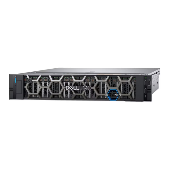
- Page 1 Dell EMC XC Core XC750xa Installation and Service Manual September 2021 Rev. 1.0...
- Page 2 A WARNING indicates a potential for property damage, personal injury, or death. © 2020 Dell Inc. or its subsidiaries. All rights reserved. Dell, EMC, and other trademarks are trademarks of Dell Inc. or its subsidiaries. Other trademarks may be trademarks of their respective owners.
-
Page 3: Table Of Contents
Contents Chapter 1: About this document....................7 Chapter 2: Dell EMC XC Core XC750xa system overview............... 8 Front view of the system..............................8 Left control panel view..............................9 Right control panel view.............................10 Rear view of the system..............................11 Inside the system ................................13 Locating the Express Service Code and Service Tag.................... - Page 4 Removing the air shroud blank..........................35 Installing the air shroud blank........................... 35 Cooling fan module................................36 Removing the cooling fan cage assembly ......................36 Installing the cooling fan cage assembly........................ 37 Removing a cooling fan..............................38 Installing a cooling fan..............................39 Side wall bracket................................40 Removing the side wall bracket..........................
- Page 5 Installing the GPU................................93 Removing the GPU riser module card holders..................... 94 Installing the GPU riser module card holders....................... 95 Optional serial COM port..............................96 Removing the serial COM port..........................96 Installing the serial COM port...........................98 Optional BOSS S2 module.............................. 99 Removing the BOSS S2 module blank........................99 Removing the BOSS S2 module..........................100 Installing the BOSS S2 module..........................
- Page 6 NIC indicator codes................................. 137 Power supply unit indicator codes..........................137 Drive indicator codes..............................139 Using system diagnostics.............................. 140 Dell Embedded System Diagnostics........................140 Chapter 9: Getting help......................141 Recycling or End-of-Life service information......................141 Contacting Dell Technologies............................141 Accessing system information by using QRL......................141 Quick Resource Locator for XC Core XC750xa system...................142...
-
Page 7: Chapter 1: About This Document
About this document This document provides an overview about the system, information about installing and replacing components, technical specifications, diagnostic tools, and guidelines to be followed while installing certain components. About this document... -
Page 8: Chapter 2: Dell Emc Xc Core Xc750Xa System Overview
● Two redundant AC or DC power supply units ● Up to 8 x 2.5-inch SAS/SATA/NVMe drives NOTE: For more information about how to hot swap NVMe PCIe SSD U.2 device, see the Dell Express Flash NVMe PCIe SSD User's Guide at https://www.dell.com/support Browse all Products >... -
Page 9: Left Control Panel View
Drive Enables you to install drives that are supported on your system. NOTE: For more information, see the Dell EMC XC Core XC750xa Technical Specifications on the product documentation page. Right control panel Contains the power button, USB port, iDRAC Direct micro port, and the iDRAC Direct status LED. -
Page 10: Right Control Panel View
You can access system inventory, Dell Lifecycle Controller logs or system logs, system health status, and also configure iDRAC, BIOS, and networking parameters. You can also launch the virtual Keyboard, Video, and Mouse (KVM) viewer and virtual Kernel- based Virtual Machine (KVM), on a supported mobile device. -
Page 11: Rear View Of The System
For more information on the expansion cards supported on your system, see Expansion card installation guidelines section. Power supply unit For more information about the PSU configurations, see the Dell EMC XC (PSU 2) Core XC750xa Technical Specifications on the product documentation page. Dell EMC XC Core XC750xa system overview... - Page 12 Description slots VGA port Enables you to connect a display device to the system. For more information, see the Dell EMC XC Core XC750xa Technical Specifications on the product documentation page. USB 3.0 port (1) This port is USB 3.0-compliant.
-
Page 13: Inside The System
12. Riser 2 cage 13. Power supply unit (PSU 2) 14. Riser 3 cage Locating the Express Service Code and Service Tag The unique Express Service Code and Service Tag are used to identify the system. Dell EMC XC Core XC750xa system overview... -
Page 14: System Information Label
The Mini Enterprise Service Tag (MEST) label is located on the rear of the system that includes Service Tag (ST), Express Service Code (Exp Svc Code), and Manufacture Date (Mfg. Date). The Exp Svc Code is used by Dell EMC to route support calls to the appropriate personnel. - Page 15 Figure 9. Memory information and system board connectors Figure 10. Cabling overview Figure 11. System tasks Figure 12. Heat sink Dell EMC XC Core XC750xa system overview...
- Page 16 Figure 13. BOSS S2 Figure 14. Electrical overview Figure 15. Configuration and layout Dell EMC XC Core XC750xa system overview...
-
Page 17: Rail Sizing And Rack Compatibility Matrix
Figure 17. Icon legend Figure 18. LED behavior Rail sizing and rack compatibility matrix For specific information about the rail solutions compatible with your system, see the Dell EMC Enterprise Systems Rail Sizing and Rack Compatibility Matrix available at https://i.dell.com/sites/csdocuments/Business_solutions_engineering- Docs_Documents/en/rail-rack-matrix.pdf. -
Page 18: Chapter 3: Initial System Setup And Configuration
Initial system setup and configuration This section describes the tasks for initial setup and configuration of the Dell EMC system. The section also provides general steps to set up the system and the reference guides for detailed information. Topics: •... -
Page 19: Options To Log In To Idrac
Table 6. Interfaces to set up iDRAC IP address (continued) Interface Documentation links iDRAC Direct Integrated Dell Remote Access Controller User's Guide at https://www.dell.com/idracmanuals or for system specific Integrated Dell Remote Access Controller User's Guide, go to https://www.dell.com/poweredgemanuals > Product Support page of your system >... -
Page 20: Resources To Install Operating System
Ensure that you change the default username and password after setting up the iDRAC IP address. For more information about logging in to the iDRAC and iDRAC licenses, see the latest Integrated Dell Remote Access Controller User's Guide at www.dell.com/idracmanuals. -
Page 21: Options To Download And Install Os Drivers
Ensure that you clear the web browser cache before downloading the drivers and firmware. Steps 1. Go to www.dell.com/support/drivers. 2. Enter the Service Tag of the system in the Enter a Dell Service Tag, Dell EMC Product ID or Model field, and then press Enter. NOTE: If you do not have the Service Tag, click Browse all products, and navigate to your product. -
Page 22: Chapter 4: Minimum To Post And System Management Configuration Validation
Minimum to POST and system management configuration validation This section describes the minimum to POST system requirement and system management configuration validation of the Dell EMC system. Topics: • Minimum configuration to POST • Configuration validation Minimum configuration to POST The components listed below are the minimum configuration to POST: ●... -
Page 23: Error Messages
Table 10. Configuration validation error (continued) Error Description Possible cause and Example recommendations Comm Error A configuration element is not responding System management sideband Comm Error: Backplane to iDRAC using the management interface communication while running an inventory check. Unplug AC Power, reseat the element and replace the element if the problem persists. -
Page 24: Chapter 5: Installing And Removing System Components
Damage due to servicing that is not authorized by Dell is not covered by your warranty. Read and follow the safety instructions that are shipped with your product. -
Page 25: Before Working Inside Your System
While replacing the hot swappable PSU, after next server boot; the new PSU automatically updates to the same firmware and configuration of the replaced one. For more information about the Part replacement configuration, see the Lifecycle Controller User's Guide at https://www.dell.com/idracmanuals. NOTE: While replacing faulty storage controller, FC, or NIC card with the same type of card, after you power on the system;... -
Page 26: Optional Front Bezel
● 1/4-inch flat blade screwdriver ● Wrist grounding strap connected to the ground ● ESD mat You need the following tools to assemble the cables for a DC power supply unit: ● AMP 90871-1 hand-crimping tool or equivalent ● Tyco Electronics 58433-3 or equivalent ●... -
Page 27: Installing The Front Bezel
Next steps Replace the front bezel. Installing the front bezel The procedure to install the front bezel with and without the LCD panel is the same. Prerequisites 1. Follow the safety guidelines listed in the Safety instructions. 2. Locate and remove the bezel key. NOTE: The bezel key is part of the LCD bezel package. -
Page 28: Installing The System Cover
Steps 1. Using a 1/4-inch flat head or a Phillips #2 screwdriver, rotate the lock counterclockwise to the unlock position. 2. Lift the release latch until the system cover slides back. 3. Lift the cover from the system. Figure 21. Removing the system cover Next steps Replace the system cover. -
Page 29: Drive Backplane Cover
Figure 22. Installing the system cover Next steps 1. Follow the procedure listed in After working inside your system. Drive backplane cover Removing the drive backplane cover Prerequisites 1. Follow the safety guidelines listed in the Safety instructions. 2. Follow the procedure listed in Before working inside your system. -
Page 30: Installing The Drive Backplane Cover
Figure 23. Removing the drive backplane cover Next steps Replace the drive backplane cover. Installing the drive backplane cover Prerequisites 1. Follow the safety guidelines listed in the Safety instructions. 2. Follow the procedure listed in Before working inside your system. - Page 31 Figure 24. Installing the drive backplane cover Next steps 1. Follow the procedure listed in After working inside your system. Installing and removing system components...
-
Page 32: Air Shroud
Air shroud Removing the air shroud Prerequisites CAUTION: Never operate your system with the air shroud removed. The system may get overheated quickly, resulting in shutdown of the system and loss of data. 1. Follow the safety guidelines listed in the Safety instructions. -
Page 33: Installing The Air Shroud
Figure 26. Removing the right air shroud Next steps Replace the air shroud. Installing the air shroud Prerequisites 1. Follow the safety guidelines listed in the Safety instructions. 2. Follow the procedure listed in Before working inside your system. 3. Remove the cables from the air shroud notch, place them on other shroud and opposite way. Steps 1. - Page 34 Figure 27. Installing the left air shroud Figure 28. Installing the right air shroud Next steps 1. Insert the cables into the air shroud notch. Black cable goes to black air shroud notch and gray cables goes to gray air shroud notch.
-
Page 35: Removing The Air Shroud Blank
Removing the air shroud blank Prerequisites CAUTION: Never operate your system with the air shroud removed. The system may get overheated quickly, resulting in shutdown of the system and loss of data. 1. Follow the safety guidelines listed in the Safety instructions. -
Page 36: Cooling Fan Module
Figure 30. Installing the left air shroud Next steps Replace the air shroud. 2. Follow the procedure listed in After working inside your system. Cooling fan module Removing the cooling fan cage assembly Prerequisites 1. Follow the safety guidelines listed in the Safety instructions. -
Page 37: Installing The Cooling Fan Cage Assembly
Figure 31. Removing the cooling fan cage assembly Next steps Install the cooling fan cage assembly. Installing the cooling fan cage assembly Prerequisites 1. Follow the safety guidelines listed in the Safety instructions. CAUTION: Ensure that the cables inside the system are correctly installed and retained by the cable retention bracket before installing the cooling fan cage assembly. -
Page 38: Removing A Cooling Fan
Figure 32. Installing the cooling fan cage assembly Next steps 1. If removed, replace the air shroud. 2. Insert the cables into cables access latch and close cable access latch. 3. Connect the cables to system board that pass through the cooling fan cage assembly cable latch. 4. -
Page 39: Installing A Cooling Fan
Figure 33. Removing a cooling fan Next steps Replace a cooling fan. Installing a cooling fan Prerequisites 1. Follow the safety guidelines listed in the Safety instructions. 2. Follow the procedure listed in Before working inside your system. Steps Align and slide the cooling fan into the cooling fan cage assembly until the fan clicks into place. NOTE: The air flow arrow on the cooling fan must face towards rear side of the system. -
Page 40: Side Wall Bracket
Figure 34. Installing a cooling fan Next steps 1. Follow the procedure listed in After working inside your system. Side wall bracket Removing the side wall bracket There are two side wall brackets on either side of the system. The procedure to remove them is same. Prerequisites 1. -
Page 41: Installing The Side Wall Bracket
Figure 35. Removing the side wall bracket Next steps Replace the side wall bracket. Installing the side wall bracket There are two side wall brackets on either side of the system. The procedure to install them is same. Prerequisites 1. Follow the safety guidelines listed in the Safety instructions. -
Page 42: Drives
Figure 36. Installing the side wall bracket Next steps Install the cooling fan cage assembly. 2. If removed, replace the air shroud. 3. If required, replace the drive backplane cover. 4. Follow the procedure listed in the After working inside your system. -
Page 43: Installing A Drive Blank
Figure 37. Removing a drive blank Next steps Replace the drive blank. Installing a drive blank Prerequisites 1. Follow the safety guidelines listed in the Safety instructions. 2. If installed, remove the front bezel. Steps Slide the drive blank into the drive slot until the release button clicks into place. Figure 38. -
Page 44: Removing The Drive Carrier
Removing the drive carrier Prerequisites 1. Follow the safety guidelines listed in the Safety instructions. 2. If installed, remove the front bezel. 3. Using the management software, prepare the drive for removal. If the drive is online, the green activity or fault indicator blinks while the drive is powering off. -
Page 45: Installing The Drive Into The Drive Carrier
NOTE: If the drive carrier has Torx screw, use Torx 6 (for 2.5-inch drive) or Torx 8 (for 3.5-inch drive) screwdriver to remove the drive. 2. Lift the drive out of the drive carrier. Figure 40. Removing the drive from the drive carrier Next steps Install the drive into the drive carrier. -
Page 46: Installing The Drive Carrier
Figure 41. Installing a drive into the drive carrier Next steps Install the drive carrier. Installing the drive carrier Prerequisites CAUTION: Before removing or installing a drive while the system is running, see the documentation for the storage controller card to ensure that the host adapter is configured correctly to support drive removal and insertion. -
Page 47: Perc Module
Figure 42. Installing a drive carrier Next steps If removed, replace the front bezel. PERC module Removing the rear mounting front PERC module Prerequisites 1. Follow the safety guidelines listed in the Safety instructions. 2. Follow the procedure listed in Before working inside your system. -
Page 48: Installing The Rear Mounting Front Perc Module
Figure 43. Removing the rear mounting front PERC module Next steps Replace the rear mounting front PERC module. Installing the rear mounting front PERC module Prerequisites 1. Follow the safety guidelines listed in the Safety instructions. 2. Follow the procedure listed in Before working inside your system. -
Page 49: Drive Backplane
Figure 44. Installing the rear mounting front PERC module Next steps 1. Connect all the cables to rear mounting front PERC module. NOTE: Route the cable properly to prevent the cable from being pinched or crimped. Replace the drive backplane cover. -
Page 50: Removing The Drive Backplane
3. BP_DST_PA1 (PCIe/NVMe connector) 4. BP_ DST_PB1 (PCIe/NVMe connector) 5. BP_ DST_PA2 (PCIe/NVMe connector) 6. BP_PWR_1 (backplane power and signal cable to system board) 7. BP_ DST_PB2 (PCIe/NVMe connector) Removing the drive backplane Prerequisites CAUTION: To prevent damage to the drives and backplane, remove the drives from the system before removing the backplane. -
Page 51: Installing The Drive Backplane
Installing the drive backplane Prerequisites 1. Follow the safety guidelines listed in the Safety instructions. 2. Follow the procedure listed in Before working inside your system. Remove the drive backplane cover. Remove all drives. 5. If required, remove NVMe connector blank. -
Page 52: Removing A Nvme Connector Blank
Removing a NVMe connector blank Prerequisites 1. Follow the safety guidelines listed in the Safety instructions. 2. If installed, remove the front bezel. Remove all drives. Remove the drive backplane cover. Remove the drive backplane CAUTION: NVMe connector blank is applicable for the system with x6 NVMe drive configuration. NOTE: NVMe connector blank must be removed from the drive backplane in order to change x6 NVMe drive configuration to other storage configuration. -
Page 53: Cable Routing
Figure 49. Installing a NVMe connector blank Next steps 1. If removed, replace the front bezel. Replace the drive backplane. Install all drives. Replace the drive backplane cover. Cable routing Figure 50. Front GPU power cables Table 14. Front GPU power cables From R4_PAD_PWR ( R4 paddle card power connector) J_36 (GPU riser module power connector) - Page 54 Table 14. Front GPU power cables (continued) From SIG_PWR_4 (system board power connector) GPU_32 (GPU card power connector) SIG_PWR_3 (system board power connector) GPU_31 (GPU card power connector) SIG_PWR_0 (system board power connector) GPU_33 (GPU card power connector) SIG_PWR_2 (system board power connector) GPU_34 (GPU card power connector) R1_PAD_PWR ( R1 paddle card power connector) J_35 (GPU riser module power connector)
- Page 55 Figure 52. 6 x 2.5-inch NVMe direct Table 16. 6 x 2.5-inch NVMe direct From Riser 3 paddle (R3 paddle card on Riser 3 slot) BP_DST_PA1 (backplane signal connector) and BP_DST_PB1 (backplane signal connector) SL7_CPU1_PA5 (signal connector on system board) BP_DST_PA2 (backplane signal connector) Figure 53.
-
Page 56: System Memory
Table 17. 8 x 2.5-inch SAS/SATA with 4 universal slots and fPERC From Riser 3 paddle (R3 paddle card on Riser 3 slot) BP_DST_PA2 (backplane signal connector) and BP_DST_PB2 (backplane signal connector) SL7_CPU1_PA5 (signal connector on system board) CTRL_DST_PA1 (fPERC input connector) System memory System memory guidelines The XC Core XC750xa system supports DDR4 registered DIMMs (RDIMMs), Load Reduced DIMM (LRDIMMs), and Intel... -
Page 57: General Memory Module Installation Guidelines
Table 18. Memory channels (continued) Processor Channel Channel Channel C Channel D Channel E Channel F Channel G Channel H Processor Slots B1 Slots B5 Slots B3 Slots B7 Slots B2 and Slots B6 Slots B4 and Slots B8 and and B9 and B13 and B11... -
Page 58: Intel Persistent Memory 200 Series (Bps) Installation Guidelines
● Populate Intel Persistent Memory 200 series (BPS) in DIMM slot 1, unless Intel Persistent Memory 200 series (BPS) is the only DIMM in that channel and then populate in DIMM slot 0. For more information about the supported Intel Persistent Memory 200 series (BPS) configurations, see the Dell EMC Intel Persistent Memory 200 series (BPS) User's Guide at https://www.dell.com/support/home/products/server_int/... - Page 59 Table 21. Supported Intel Persistent Memory 200 series (BPS) for dual processor configurations Configuration Description per Memory population rules processor RDIMMs or LRDIMMs Intel Persistent Memory 200 series (BPS) Configuration 1 4 x RDIMMs, 4 x Intel Processor1 {A1, 2, 3, 4} Processor1 {A5, 6, 7 ,8} Persistent Memory 200 Processor2 {B1, 2, 3, 4}...
- Page 60 Table 22. Intel Persistent Memory 200 series (BPS) Configuration 1 - 4 x RDIMMs/ LRDIMMs, 4 x Intel Persistent Memory 200 series (BPS) per processor (continued) Total No of Total No of 1 R/LRDIMM 1 Intel Total Standard Total PM Supported RDIMMs/ Intel Persistent...
- Page 61 Table 24. Intel Persistent Memory 200 series (BPS) Configuration 3 - 8 x RDIMMs/ LRDIMMs, 1 x Intel Persistent Memory 200 series (BPS) per processor (continued) Total No of Total No of 1 R/LRDIMM 1 Intel Total Standard Total PM Supported Modes RDIMMs / Intel...
-
Page 62: Removing A Memory Module
Table 26. Intel Persistent Memory 200 series (BPS) Configuration 5 - 8 x RDIMMs/ LRDIMMs, 8 x Intel Persistent Memory 200 series (BPS) per processor (continued) Total No of Total No of 1 R/LRDIMM 1 Intel Total Standard Total PM Supported Modes RDIMMs / Intel... -
Page 63: Installing A Memory Module
2. To release the memory module from the socket, simultaneously press the ejectors on both ends of the memory module socket to fully open. CAUTION: Handle each memory module only by the card edges, ensuring not to touch the middle of the memory module or metallic contacts. -
Page 64: Processor And Heat Sink Module
CAUTION: Do not apply pressure at the center of the memory module; apply pressure at both ends of the memory module evenly. 4. Press the memory module with your thumbs until the ejectors firmly click into place. When the memory module is properly seated in the socket, the levers on the memory module socket align with the levers on the other sockets that have memory modules installed. - Page 65 Steps 1. Place the heat sink with the processor side facing up. 2. Using your thumb, lift up the Thermal Interface Material (TIM) break lever to release the processor from the TIM and retaining clip. 3. Holding the processor by the edges, lift the processor away from the retaining clip. NOTE: Ensure to hold the retaining clip to the heat sink as you lift the TIM break lever.
-
Page 66: Installing The Processor
Figure 58. Removing the retaining clip Next steps Replace the processor. Installing the processor Prerequisites 1. Follow the safety guidelines listed in the Safety instructions. 2. Follow the procedure listed in Before working inside your system. Remove the air shroud. 4. - Page 67 Figure 59. Installing the retaining clip 3. Align the processor with retaining clip, by using the fingers press the retaining clip on all the four sides until it clicks into place. NOTE: Ensure the processor is securely latched to the retaining clip. Figure 60.
- Page 68 CAUTION: Applying too much thermal grease can result in excess grease coming in contact with and contaminating the processor socket. NOTE: The thermal grease syringe is intended for single use only. Dispose the syringe after you use it. Figure 61. Applying thermal grease 6.
-
Page 69: Expansion Cards And Expansion Card Risers
A system event entry is logged in the iDRAC Lifecycle Controller if an expansion card riser is not supported or missing. It does not prevent your system from turning on. However, if a F1/F2 pause occurs with an error message, see Troubleshooting expansion cards section in the Dell EMC PowerEdge Servers Troubleshooting Guide at https:// www.dell.com/poweredgemanuals. -
Page 70: Expansion Card Installation Guidelines
Expansion card installation guidelines Figure 64. Expansion card slot connectors 1. GPU riser module left for R4 paddle card (slot 31 and slot 32) 2. Riser 3 (slot 4 and slot 5) 3. Riser 2 (slot 3 and slot 6) 4. - Page 71 Table 28. Riser configurations (continued) Configurations Expansion PCIe Slots Controlling height Length Slot width card risers processor with R1 paddle card GPU riser 31 and 32 Processor 2 Full Height, Full length¹ x16 + x16 module left double width with R4 paddle card Config1-1.
- Page 72 Figure 66. Riser 3B 1. Slot 5 2. Slot 4 Figure 67. GPU riser module right 1. Slot 34 2. Slot 33 Figure 68. GPU riser module left 1. Slot 32 2. Slot 31 NOTE: The expansion-card slots are not hot-swappable. The following table provides guidelines for installing expansion cards to ensure proper cooling and mechanical fit.
-
Page 73: Removing The Expansion Card Risers
Table 29. Config0-1. R2A + R3B + GPU riser module right with R1 paddle card + GPU riser module left with R4 paddle card (without NVbridge) Card type Slot priority Maximum number of cards Inventec (VGA) - FH 4, 5 Inventec (VGA) - LP Inventec (Serial) - FH 4, 5... - Page 74 NOTE: The numbers on the image do not depict the exact steps. The numbers are for representation of sequence. Figure 69. Removing the expansion card riser (Riser 3) NOTE: To remove Riser 2, first Riser 1 blank and if installed, BOSS S2 cable and module must be removed. Figure 70.
- Page 75 Figure 71. Removing the expansion card riser (Riser 2) 3. If the risers are not going to be replaced, install riser blanks and tighten the captive screws. NOTE: You must install a filler bracket over an empty expansion card slot to maintain Federal Communications Commission (FCC) certification of the system.
-
Page 76: Installing The Expansion Card Risers
Install Riser 2 before installing Riser 1 blank and Riser 3. CAUTION: Do not install GPUs, network cards, or other PCIe devices on your system that are not validated and tested by Dell. Damage caused by unauthorized and invalidated hardware installation will null and void the system warranty. Steps 1. - Page 77 Figure 74. Removing the Riser 3 blank Figure 75. Removing the Riser 2 blank 2. Holding the edges or the touch points, align the holes on the expansion card riser with the guides on the system board. 3. Lower the expansion card riser into place and press the touch points until the expansion card riser connector is fully seated on the system board connector.
- Page 78 Figure 76. Installing the expansion card riser (Riser 2) Figure 77. Installing the Riser 1 blank Installing and removing system components...
-
Page 79: Removing Expansion Card From The Expansion Card Riser
Figure 78. Installing the expansion card riser (Riser 3) Next steps 1. If required, re-connect the cables to the expansion card. Replace the air shroud. 3. Follow the procedure listed in After working inside your system. 4. Install any device drivers required for the card as described in the documentation for the card. Removing expansion card from the expansion card riser Prerequisites 1. - Page 80 Figure 79. Removing expansion card from the expansion card riser 4. If the expansion card is not going to be replaced, install a filler bracket and close the card retention latch. Figure 80. Installing the filler bracket Next steps 1. If applicable, install an expansion card into the expansion car riser.
-
Page 81: Installing An Expansion Card Into The Expansion Card Riser
Installing an expansion card into the expansion card riser Prerequisites 1. Follow the safety guidelines listed in the Safety instructions. 2. Follow the procedure listed in Before working inside your system. Remove the air shroud. Remove the expansion card riser. 5. -
Page 82: Removing R1 And R4 Paddle Cards
Figure 82. Installing an expansion card into the expansion card riser Next steps 1. If applicable, connect the cables to the expansion card. Replace the expansion card riser. Replace the air shroud. 4. Follow the procedure listed in After working inside your system. -
Page 83: Installing R1 And R4 Paddle Cards
Figure 83. Removing the R1 paddle card Figure 84. Removing the R4 paddle card Next steps Install the R1 and R4 paddle cards. Installing R1 and R4 paddle cards Prerequisites 1. Follow the safety guidelines listed in the Safety instructions. 2. -
Page 84: Removing The R3 Paddle Card
2. Lower the paddle card into place and press until the paddle card connector is fully seated with audible sound on the system board connector. Figure 85. Installing the R1 paddle card Figure 86. Installing the R4 paddle card Next steps Install the cooling fan cage assembly Replace the air shroud. -
Page 85: Installing The R3 Paddle Cards
5. Remove the paddle card slimline cable from cable access latch on cooling fan cage and also from the air shroud notch. Steps Press the blue release tab on the paddle card and holding the edges lift the paddle card from the riser connector on the system board. -
Page 86: Replacing The Gpu Bracket
Figure 88. Installing the R3 paddle card Next steps 1. Insert the paddle card slimline cable into the cable access latch on cooling fan cage and also through the air shroud notch. 2. If removed, replace the rear mounting front PERC module. - Page 87 Figure 89. Removing the standard bracket with two screws Figure 90. Removing the standard bracket with three screws 2. Align the custom bracket with the screw holes on the GPU card and using Philips #1 screwdriver tighten the screws (4 ± 0.5 in-lbs).
-
Page 88: Removing The Gpu Riser Module
Figure 92. Installing the custom bracket with three screws Next steps Install the GPU card. 2. Follow the procedure listed in After working inside your system. Removing the GPU riser module The procedures to remove left and right GPU riser modules are similar. Prerequisites 1. - Page 89 Figure 93. Removing the right GPU riser module Figure 94. Removing the left GPU riser module Next steps Replace the GPU riser module. Installing and removing system components...
-
Page 90: Installing The Gpu Riser Module
Installing the GPU riser module The procedure to install left and right GPU riser module are similar. Prerequisites 1. Follow the safety guidelines listed in the Safety instructions. 2. Follow the procedure listed in Before working inside your system. Remove the air shroud. -
Page 91: Removing The Gpu
Figure 96. Installing the left GPU riser module Next steps 1. If removed, install the NVLink sponges. Replace the rear mounting front PERC module. 3. Connect the GPU power and signal cables to the system board. 4. Connect the R1 and R4 paddle cards to the system board. - Page 92 Figure 97. Removing the GPU 2. If you are not replacing the GPU card, install a GPU blank if the adjacent card is double-width card. Install filler blank, if the adjacent card in not double-width card. NOTE: You must install a GPU blank over an empty GPU card slot to maintain Federal Communications Commission (FCC) certification of the system.
-
Page 93: Installing The Gpu
For instructions, see the documentation accompanying the card. CAUTION: Do not install GPUs, network cards, or other PCIe devices on your system that are not validated and tested by Dell. Damage caused by unauthorized and invalidated hardware installation will null and void the system warranty. Steps 1. -
Page 94: Removing The Gpu Riser Module Card Holders
Figure 100. Installing GPU on GPU riser module Next steps 1. If removed, install the NVLInk bridges. Install the GPU riser module. 3. If removed, install the NVLink sponges. 4. Follow the procedure listed in After working inside your system. Removing the GPU riser module card holders Prerequisites 1. -
Page 95: Installing The Gpu Riser Module Card Holders
Figure 102. Removing the FH card holder Next steps Replace the GPU riser module holders. Installing the GPU riser module card holders Prerequisites 1. Follow the safety guidelines listed in the Safety instructions. 2. Follow the procedure listed in Before working inside your system. -
Page 96: Optional Serial Com Port
Figure 104. Installing the FH card holder Next steps Install the GPU riser module. 2. Follow the procedure listed in After working inside your system. Optional serial COM port Removing the serial COM port The procedure to remove serial COM port from Riser 2 is same. Prerequisites 1. - Page 97 Figure 105. Disconnecting the serial COM port 4. Open the latch on the expansion card riser and slide the serial COM port out of the expansion card riser. Figure 106. Removing the Serial COM port 5. Install the filler bracket if not replacing the serial COM port. Next steps Replace the serial COM port.
-
Page 98: Installing The Serial Com Port
Installing the serial COM port The procedure to install serial COM port on Riser 2 is same. Prerequisites 1. Follow the safety guidelines listed in the Safety instructions. 2. Follow the procedure listed in Before working inside your system. Remove the air shroud. -
Page 99: Optional Boss S2 Module
Figure 108. Connecting the serial COM port Next steps Replace the air shroud. 2. Follow the procedure listed in After working inside your system. Optional BOSS S2 module Removing the BOSS S2 module blank Prerequisites Follow the safety guidelines listed in the Safety instructions. -
Page 100: Removing The Boss S2 Module
Figure 109. Removing the BOSS S2 module blank Next steps 1. Replace the BOSS S2 module blank or install the BOSS S2 module. Removing the BOSS S2 module Prerequisites 1. Follow the safety guidelines listed in the Safety instructions. 2. Follow the procedure listed in the Before working inside your system. - Page 101 Figure 110. Removing the BOSS S2 card carrier 3. Using the Phillips #1 screwdriver remove the M3 x 0.5 x 4.5 mm screw that secures the M.2 SSD to the BOSS S2 card carrier. 4. Slide the M.2 SSD out from the BOSS S2 card carrier. Figure 111.
-
Page 102: Installing The Boss S2 Module
Figure 112. Removing the BOSS S2 module 8. Remove the BOSS S2 power and signal cable from the BOSS S2 module. Figure 113. Removing the BOSS S2 power and signal cable from the BOSS S2 module Next steps Replace the BOSS S2 module or replace the BOSS S2 module blank. - Page 103 2. Follow the procedure listed in Before working inside your system. Steps 1. Connect the BOSS S2 power and signal cables to the connectors on the BOSS S2 module. Figure 114. Connecting the BOSS S2 power and signal cables to the BOSS S2 module 2.
- Page 104 8. Using the Phillips #1 screwdriver, secure the M.2 SSD on the BOSS S2 card carrier with the M3 x 0.5 x 4.5 mm screw. Figure 116. Installing the M.2 SSD 9. Slide the BOSS S2 card carrier into the BOSS S2 module slot. 10.
-
Page 105: System Battery
System battery Replacing the system battery Prerequisites WARNING: There is a danger of a new battery exploding if it is incorrectly installed. Replace the battery only with the same or equivalent type That is recommended by the manufacturer. Discard used batteries according to the manufacturer's instructions. -
Page 106: Intrusion Switch Module
Figure 119. Installing the system battery Next steps Install the expansion card risers. 2. If applicable, connect the cables to one or more expansion cards. 3. Follow the procedure listed in After working inside your system. 4. Confirm that the battery is operating properly, by performing the following steps: a. -
Page 107: Installing The Intrusion Switch Module
Figure 120. Removing the intrusion switch module Next steps Replace the intrusion switch module. Installing the intrusion switch module Prerequisites 1. Follow the safety guidelines listed in the Safety instructions. 2. Follow the procedure listed in Before working inside your system. -
Page 108: Optional Ocp Card
Figure 121. Installing the intrusion switch module Next steps Install the expansion card riser. 2. Follow the procedure listed in After working inside your system. Optional OCP card Removing the OCP card Prerequisites 1. Follow the safety guidelines listed in the Safety instructions. -
Page 109: Installing The Ocp Card
Figure 122. Removing the OCP card 4. If the OCP card is not going to be replaced, install a filler bracket. Figure 123. Installation of filler bracket Next steps Replace the OCP card. Installing the OCP card Prerequisites 1. Follow the safety guidelines listed in the Safety instructions. -
Page 110: Power Supply Unit
While replacing the hot swappable PSU, after next server boot; the new PSU automatically updates to the same firmware and configuration of the replaced one. For more information about the Part replacement configuration, see the Lifecycle Controller User's Guide at https://www.dell.com/idracmanuals Installing and removing system components... -
Page 111: Hot Spare Feature
● If the load on the active PSU falls below 20 percent of PSU rated power wattage, then the redundant PSU is switched to the sleep state. You can configure the hot spare feature by using the iDRAC settings. For more information, see the iDRAC User’s Guide available at https://www.dell.com/poweredgemanuals. Removing a power supply unit blank Prerequisites... -
Page 112: Installing A Power Supply Unit
NOTE: For information about the cable management when the PSU is removed or installed while the system is in a rack, see the system’s cable management arm documentation at https://www.dell.com/poweredgemanuals. Steps Press the release latch and holding the PSU handle, slide the PSU out of the bay. -
Page 113: Trusted Platform Module
PSU is removed or installed while the system is in the rack, see the system’s cable management accessory documentation at https://www.dell.com/poweredgemanuals. 2. Connect the power cable to the PSU, and plug the cable into a power outlet. -
Page 114: Initializing Tpm For Users
Removing the TPM Steps 1. Locate the TPM connector on the system board. 2. Press to hold the module down and remove the screw using the security Torx 8-bit shipped with the TPM module. 3. Slide the TPM module out from its connector. 4. -
Page 115: System Board
System board Removing the system board Prerequisites CAUTION: If you are using the Trusted Platform Module (TPM) with an encryption key, you may be prompted to create a recovery key during program or System Setup. Be sure to create and safely store this recovery key. If you replace this system board, you must supply the recovery key when you restart your system or program before you can access the encrypted data on your drives. -
Page 116: Installing The System Board
Figure 130. Removing the system board Next steps Install the system board. Installing the system board Prerequisites NOTE: Before replacing the system board, replace the old iDRAC MAC address label in the Information tag with the iDRAC MAC address label of the replacement system board 1. - Page 117 Upgrading the Trusted Platform Module section. 4. If you are not using Easy restore, import your new or existing iDRAC Enterprise license. For more information, see the Integrated Dell Remote Access Controller User's Guide available at https://www.dell.com/idracmanuals 5. Follow the procedure listed in After working inside your system.
-
Page 118: Restoring The System Using Easy Restore
Restoring the system using Easy Restore The easy restore feature enables you to restore your service tag, license, UEFI configuration, and the system configuration data after replacing the system board. All data is backed up in a backup flash device automatically. If BIOS detects a new system board, and the service tag in the backup flash device, BIOS prompts the user to restore the backup information. -
Page 119: Installing The Lom Card And Rear I/O Board
Figure 132. Removing the LOM card and rear I/O board Figure 133. Removing liquid cooling rear I/O board Next steps Replace the LOM card and rear I/O board. Installing the LOM card and rear I/O board Prerequisites 1. Follow the safety guidelines listed in the Safety instructions. - Page 120 NOTE: The procedure to install the liquid cooling rear I/O board and rear I/O board is same. Steps 1. Align the connectors and slots on the LOM card or rear I/O board with the connector and standoffs on the system board. 2.
-
Page 121: Control Panel
Control panel Removing the right control panel Prerequisites 1. Follow the safety guidelines listed in the Safety instructions. 2. Follow the procedure listed in Before working inside your system. Remove the drive backplane cover. 4. If installed, remove the air shroud. -
Page 122: Installing The Right Control Panel
Installing the right control panel Prerequisites 1. Follow the safety guidelines listed in the Safety instructions. 2. Follow the procedure listed in Before working inside your system. Remove the drive backplane cover. 4. If installed, remove the air shroud. Remove the cooling fan cage assembly. -
Page 123: Removing The Left Control Panel
Removing the left control panel Prerequisites 1. Follow the safety guidelines listed in the Safety instructions. 2. Follow the procedure listed in Before working inside your system. remove the drive backplane cover. 4. If installed, remove the air shroud. Remove the cooling fan cage assembly. -
Page 124: Installing The Left Control Panel
Installing the left control panel Prerequisites 1. Follow the safety guidelines listed in the Safety instructions. 2. Follow the procedure listed in Before working inside your system. Remove the drive backplane cover. 4. If installed, remove the air shroud. Remove the cooling fan cage assembly. -
Page 125: Chapter 6: Upgrade Kits
Upgrade Kits The table lists the available After Point Of Sale [APOS] kits. Table 30. Upgrade kits Kits Related links to service instructions Bezel Installing the front bezel GPU kit Accelerator enablement kit GPU kit Hard drives Installing drives Hard drives SSD Installing the drive into the carrier Memory Installing a memory module... -
Page 126: Gpu Kit
CAUTION: Do not install GPUs, network cards, or other PCIe devices on your system that are not validated and tested by Dell. Damage caused by unauthorized and invalidated hardware installation will null and void the system warranty. WARNING: Consumer-Grade GPU should not be installed or used in the Enterprise Server products. - Page 127 3. If installing GPU other than T4 into front GPU riser module then, replace the GPU bracket. 4. If installing T4 GPU into front GPU riser module then, install the GPU riser module card holders. install the GPU into front GPU riser module or install the GPU into expansion card riser.
-
Page 128: Chapter 7: Jumpers And Connectors
Jumpers and connectors This section provides essential and specific information about jumpers and switches. It also describes the connectors on the various boards in the system. Jumpers on the system board help to disable the system and reset the passwords. To install components and cables correctly, you must be able to identify the connectors on the system board. - Page 129 Table 35. System board jumpers and connectors (continued) Item Connector Description PSU 2 Power supply unit 2 IO_RISER4 (CPU2) Riser 4 BAT_PWR_2U NVDIMM battery power IO_RISER3 (CPU2) Riser 3 SIG_PWR_3 Power connector 3 - use for GPU only J_R3_PCIE_PWR PCIe riser 3 power Rear I/O connector Rear I/O connector SL5_PCH_SA3_PA3...
-
Page 130: System Board Jumper Settings
Damage due to servicing that is not authorized by Dell is not covered by your warranty. Read and follow the safety instructions that are shipped with your product. - Page 131 NOTE: If you assign a new system and/or setup password with the jumper on pins 4 and 6, the system disables the new password(s) the next time it boots. 5. Reconnect the system and all the attached peripherals. 6. Power off the system. 7.
-
Page 132: Chapter 8: System Diagnostics And Indicator Codes
System diagnostics and indicator codes This section describes the diagnostic indicators on the system front panel display system status during system startup. Topics: • Status LED indicators • System health and system ID indicator codes • iDRAC Quick Sync 2 indicator codes •... -
Page 133: System Health And System Id Indicator Codes
For information about the event and error messages generated by the system firmware and agents that monitor system components, go qrl.dell.com > Look Up > Error Code, type the error code, and then click Look it... -
Page 134: Idrac Quick Sync 2 Indicator Codes
If the problem persists, see the Getting help section. https://www.dell.com/poweredgemanuals. Solid amber Indicates that the system is in fail-safe Restart the system. If the problem persists, see mode. Getting help section. -
Page 135: Lcd Panel
The LCD panel is used to configure or view the iDRAC IP address of the system. For information about the event and error messages generated by the system firmware and agents that monitor system components, go to qrl.dell.com >... -
Page 136: Setup Menu
For information about the event and error messages generated by the system firmware and agents that monitor system components, go to qrl.dell.com > Look Up > Error Code, type the error code, and then click Look it up.. -
Page 137: Nic Indicator Codes
NIC indicator codes Each NIC on the back of the system has indicators that provide information about the activity and link status. The activity LED indicator indicates if data is flowing through the NIC, and the link LED indicator indicates the speed of the connected network. Figure 144. - Page 138 Table 45. AC PSU status indicator codes Power indicator codes Condition Green Indicates that a valid power source is connected to the PSU and the PSU is operational. Blinking amber Indicates an issue with the PSU. Not powered on Indicates that the power is not connected to the PSU. Blinking green Indicates that the firmware of the PSU is being updated.
-
Page 139: Drive Indicator Codes
Table 46. DC PSU status indicator codes (continued) Power indicator codes Condition Output configuration or conversely, you must power off the system. CAUTION: Combining AC and DC PSUs is not supported. Drive indicator codes The LEDs on the drive carrier indicates the state of each drive. Each drive carrier has two LEDs: an activity LED (green) and a status LED (bicolor, green/amber). -
Page 140: Using System Diagnostics
Using system diagnostics If you experience an issue with the system, run the system diagnostics before contacting Dell for technical assistance. The purpose of running system diagnostics is to test the system hardware without using additional equipment or risking data loss. -
Page 141: Chapter 9: Getting Help
Dell contact information on your purchase invoice, packing slip, bill or Dell product catalog. The availability of services varies depending on the country and product, and some services may not be available in your area. To contact Dell for sales, technical... -
Page 142: Quick Resource Locator For Xc Core Xc750Xa System
Dell EMC. This information is used by Dell EMC Technical Support to troubleshoot the issue. ● Proactive contact — A Dell EMC Technical Support agent contacts you about the support case and helps you resolve the issue. -
Page 143: Chapter 10: Documentation Resources
This section provides information about the documentation resources for your system. To view the document that is listed in the documentation resources table: ● From the Dell EMC support site: 1. Click the documentation link that is provided in the Location column in the table. - Page 144 For information about updating drivers and https://www.dell.com/support/drivers firmware, see the Methods to download firmware and drivers section in this document. Managing your system For information about installing and using Dell https://www.dell.com/serviceabilitytools SupportAssist, see the Dell EMC SupportAssist Enterprise User’s Guide. Working with the Dell For information about understanding the https://www.dell.com/...