Toro GROUNDSMASTER 455-D Operator's Manual
Hide thumbs
Also See for GROUNDSMASTER 455-D:
- Service manual (254 pages) ,
- Operator's manual (37 pages) ,
- Operator's manual (36 pages)

Related Manuals for Toro GROUNDSMASTER 455-D


Summary of Contents for Toro GROUNDSMASTER 455-D
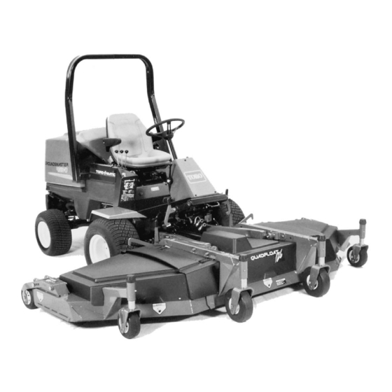
- Page 1 3325-366 Rev A OPERATOR S MODEL NO. 30450 2100 00001 & UP 00001 MODEL NO. 30455TC 2100 & UP MANUAL ¤ ¤ GROUNDSMASTER 455-D © The Toro Company—2000...
-
Page 2: Table Of Contents
Table of Contents Table of Contents Changing Bi-Directional Clutch Lubricant (Model 30455 Only) Safety Rear Wheel Toe In Sound & Vibration Levels Adjusting Service Brakes Adjusting Pro Belt Symbol Glossary Adjusting The Clutch Battery Care Specifications Fuses Before Operating Cutting Unit Maintenance Check The Engine Oil General Maintenance Check The Cooling System... -
Page 3: Safety
E. Wipe up any spilled fuel. A free replacement manual is available by sending the complete model and serial number to: While Operaing The Toro Company Sit on the seat when starting and operating the 8111 Lyndale Avenue South machine. - Page 4 engine is running or soon after it is stopped. These prevent loss of control: areas could be hot enough to cause burns. A. Operate only in daylight or when there is good artificial light. 23. If cutting deck strikes a solid object or vibrates abnormally, stop immediately, turn engine off, set B.
-
Page 5: Sound & Vibration Levels
Toro distributor. Sound Pressure Level 32. To reduce potential fire hazard, keep engine area This unit has an equivalent continuous A-weighted free of excessive grease, grass, leaves and dirt. sound pressure at the operator ear of: 89 dB(A), based... -
Page 6: Symbol Glossary
Symbol Glossary Caustic liquids, Poisonous Electrical shock, High pressure High pressure High pressure Crushing of Crushing of chemical burns to fumes or toxic electrocution fluid, injection spray, erosion of spray, erosion of fingers or hand, toes or foot, force fingers or hand gases, asphyxiation into body flesh... - Page 7 Consult technical Fasten seat Safety alert Outline safety Read operator’s Fire, open light Eye protection manual for proper belts triangle alert symbol manual and smoking must be worn service prohibited procedures Head protection Hearing Caution, toxic First aid Flush with water Engine Transmission Hydraulic system must be worn...
- Page 8 n/min Engine start Engine stop Engine failure/ Engine rotational Choke Primer (start aid) Electrical preheat Transmission malfunction speed/frequency (low temperature start aid) N H L F Transmission Transmission Transmission Clutch Neutral High Forward oil pressure oil temperature failure/malfunction Reverse Hydraulic oil Hydraulic oil Second gear Hydraulic oil...
-
Page 9: Specifications
Specifications Traction Unit Automotive type, full power. Steering System: Totally enclosed, non asbestos, dry multi-disc Brakes: Peugeot, four-cycle, four-cylinder, 1.9 liter Engine: individual wheel and parking brakes on front traction (1,900 cc) displacement, liquid-cooled diesel engine. wheels. Brakes controlled by individual pedals operated 23.5:1 compression ratio. - Page 10 Distributor (Standard on Model 30455) (19 inches) long, 6 mm (1/4”) thick, and 64 mm (2-1/2 in.) wide, heat treated steel blades. 4-Post Canopy Kit, Contact Your Local Toro Distributor Spark Arrestor Muffler, Part No. 94-5637 Self-tensioning permanently lubricated Belt Idlers: idlers.
-
Page 11: Before Operating
If the coolant is low, remove the degasser tank cap area on the dipstick. and add a 50/50 mixture of water and Peugeot recommended anti-freeze (Toro Part No. 93-7213). Do not use water only or alcohol/ methanol- based coolants. IMPORTANT: Do not remove the black plastic cap on the degasser tank. -
Page 12: Check The Hydraulic Circuit Oil
Note: The fluids within this group are interchangeable. ISO VG 46/68 multi-viscosity anti-wear hydraulic fluid Mobil DTE 15M Amoco Rykon Premium ISO 46 Castrol AWH 46 Conoco Hydroclear AW MV46 Gulf Harmony HVI 46 AW Kendall Hyken Golden MV SAE 5W-20 Pennzbell AWX MV46 Phillips... -
Page 13: Check The Front Axle Oil Level
One bottle is sufficient signs of oil loss. for 22 L of hydraulic fluid. Order Part No. 44-2500 from your Authorized Toro Distributor. Park the machine on a level surface. Park the machine on a level surface. Make sure the Remove the access panel (Fig. -
Page 14: Check The Rear Axle Lubricant
Screw the dipstick filler cap finger-tight onto the filler neck. It is not necessary to tighten the cap with a wrench. Figure 9 1. Check/fill plug Check Bi-Directional Clutch Lubricant Figure 7 1. Dipstick cap (Model 30455 Only) (Fig. 10) Check the Rear Axle Lubricant The Bi-directional Clutch is shipped from the factory filled with Mobil DTE 15 M anti-wear hydraulic fluid. -
Page 15: Check Tire Pressure
Check Tire Pressure The tires are over-inflated for shipping. Therefore, release some of the air to reduce the pressure. Correct air pressure in the front and rear tires is 138 kPa (20 psi). IMPORTANT: Maintain even pressure in all tires to assure a good quality-of-cut and proper machine performance. - Page 16 Rear Castor Wheels HEIGHT OF CUT —REAR DECK STRAPS Remove the hairpin cotter and height-of-cut pin securing the rear castor pivot arm to the deck bracket. Start the engine and raise the cutting unit so the height-of-cut can be changed. Stop the engine after the cutting unit is raised.
-
Page 17: Safety Doors
Safety Doors On each side of the center deck is a safety door that opens and closes as the wing decks are lowered and raised (Fig. 13). The doors open to provide overlap of the cutting blades when the wing units are down. The doors close to provide safety and protection when the wing units are raised. -
Page 18: Controls
Controls lever raises and lowers the whole cutting unit. The Cutting Unit Engagement Switch (Fig. 16)—Used to start and stop cutting unit operation. Lift switch and move engine must be running to lower the cutting unit. When forward to actuate the cutting unit. Center deck will engage wing cutting units are raised higher than 15°, their first followed by wing decks engaging approximately one blades automatically disengage. - Page 19 or when going uphill, keep the engine rpm high by having the throttle in FAST and the traction pedal partially engaged. If engine rpm begins to decrease due to load, gradually reduce the traction pedal pressure until engine speed is increased. To stop, reduce foot pressure on the traction pedal and allow it to return to the center position.
-
Page 20: Operating
Operating Starting and Stopping Sit on the seat and keep your foot off the traction pedal. Assure the parking brake is engaged, the traction pedal is in NEUTRAL and the cutting unit engagement switch is in the DISENGAGED position. Turn the ignition switch to ON. When the glow plug indicator light goes off, the engine is ready to START. -
Page 21: Operating Characteristics
CAUTION WARNING The interlock switches are for the operator’s When operating a 4-wheel drive machine, always use protection, so do not disconnect them. Check switch the seat belt and Roll-Over Protection System together operation daily to assure the interlock system is and have the seat pivot retaining pin installed. -
Page 22: Operating Tips
cutting unit and raise it by pulling back on the cutting Operating Tips unit lift control levers. Hold the levers back until the cutting unit is fully raised. Never raise the cutting deck Mow When Grass Is Dry—Mow either in the late when it is engaged. -
Page 23: Maintenance
Maintenance Minimum Recommended Maintenance Intervals Maintenance Procedure Maintenance Interval & Service Every Every Every Every Every Inspect the air filter, dust cup and baffle 800 hours Lubricate all grease fittings hours hours hours hours Check cutting unit gear box oil level ‡... - Page 24 2-Wheel Drive 4-Wheel Drive CHECK/FILL Engine oil level/fill Engine oil level/fill Hydraulic oil level/fill Hydraulic oil level/fill Front axle oil level/fill Front axle oil level/fill Rear axle oil level Rear axle oil level A. Fill A. Fill B. Check (2) B.
-
Page 25: Greasing
Greasing (Fig. 23–35) The traction and cutting units have grease fittings that must be lubricated regularly with No. 2 General Purpose Lithium Base Grease. If the machine is operated under normal conditions, lubricate all grease fittings after every 25 hours of operation. Lubricate all grease fittings immediately after every washing, regardless of interval listed. - Page 26 Figure 26 Figure 29 Figure 30 Figure 27 Figure 31 Figure 28...
- Page 27 Figure 32 Fig. 35 Fig. 36 Fig. 33 Fig. 37 Fig. 34...
-
Page 28: General Air Cleaner Maintenance
General Air Cleaner Maintenance WARNING Before servicing or making adjustments to the machine, stop engine and remove key from the switch. Check air cleaner body for damage that could possibly cause an air leak. Replace a damaged air cleaner body. Figure 39 1. -
Page 29: Engine Oil And Filter
C (160°F) max), or allow the element to air dry. Do not use a light bulb to dry the filter element because damage could result. Compressed Air Method A. Blow compressed air from inside to the outside of dry filter element. Do not exceed 689 kPa (100 psi) to prevent damage to the element. -
Page 30: Engine Cooling System
Drain and clean the fuel tank every 800 hours of filter from the assembly. Note the position of the operation or yearly, whichever comes first. Also, drain gaskets and O-ring when disassembling from them and clean the tank if the fuel system becomes the filter. -
Page 31: Engine Timing Belt
B. After every 2 years or 1500 hours, drain and and filter after every 800 operating hours. If oil flush the cooling system. Add anti-freeze becomes contaminated, contact your local TORO (refer to Check Cooling System). distributor because the system must be flushed. -
Page 32: Replacing The Hydraulic Filter
Oil. whichever comes first. IMPORTANT. Use only hydraulic oils specified. Only the Toro replacement filter (Part No. 86-301 0) can Other fluids could cause system damage. be used in the hydraulic system. IMPORTANT: Use of any other filter may void the warranty on some components. -
Page 33: Checking Hydraulic Lines And Hoses
1. Charge pressure Check all pressures when engine is at full speed and hydraulic oil is at normal operating temperature. Contact your local Toro distributor for assistance. Traction Forward and Reverse have a normal relief setting of approximately 41,000 kPa (6000 psi). -
Page 34: Adjusting The Traction Drive For Neutral
5. Tighten the locknut locking adjustment. 6. Stop the engine and release the right brake. Remove the jack stands and lower the machine to the shop floor. Test drive the machine to make sure it does not creep. WARNING The engine must be running so that final adjustment of the traction adjustment cam can be performed. -
Page 35: Changing Rear Axle Lubricant
Changing Rear Axle Lubricant (Model 30455 only) After every 800 hours of operation the oil in the rear axle must be changed. Position the machine on a level surface. Clean the area around the (3) drain plugs, (1) on each end and (1) in the center (Fig. 56). Figure 57 1. -
Page 36: Adjusting Service Brakes
A. Loosen the clamps at both ends of the tie rods. pedal. B. Rotate the tie rod to move the front of the tire inward or outward. C. Tighten the tie rod clamps when adjustment is correct. To adjust 4-wheel drive models (Fig. 59): A. -
Page 37: Adjusting The Clutch
Check clutch the battery posts and cable connectors with Grafo 11 2X adjustment initially after the first 10 hours of operation, (skin -over) grease (Toro Part No. 505-47) or petroleum thereafter, check every 200 hours. jelly to prevent corrosion. -
Page 38: General Maintenance
Cutting Unit Maintenance WARNING WARNING Do not start the engine and engage the PTO To prevent the engine from starting accidentally while switch when the PTO shaft is not connected to you are performing maintenance, shut the engine of the gear box on the cutting unit. If engine is and remove the key from the ignition switch. -
Page 39: Cutting Unit Maintenance
all lift levers are in the float position and stop the Alternate Method engine. Lower the center and wing cutting units to the Connect the wire harness and (3) hydraulic lines ground, set the parking brake and stop the engine. couplers at the rear of the deck. -
Page 40: Safety Door Adjustment
Torque the screws to 27–34 Nm (20–25 ft-lb.). Rotate the threaded rod to raise or lower the edge of the door until it is even or 6mm higher than the Start the engine, raise the center cutting unit lower edge of the door guide when wing decks are slightly so that the rear deck straps can be mounted in the fully raised, transport position. - Page 41 adjustor tube to top of the cutting deck. Loosen the jam nut on the adjusting screw and turn the screw until the black plastic sleeve is flush (even) with the edge of the idler support. When distance is attained, tighten the jam nut on the adjusting screw and (2) flange head nuts securing the idler adjustor tube to the top of the Figure 71...
-
Page 42: Adjusting Belt Tension
Remove the capscrews and nuts securing the front of the gear box support to the deck channels and loosen the capscrews securing the rear of the gear box support to the deck channels. Figure 73 1. Spring-loaded idler pulley 2. Stationary idler pulley Figure 75 Remove the hair pin cotter securing the clutch rod 1. -
Page 43: Servicing Front Bushings In Castor Arms
15. Check the idler pulley adjustment, refer to the top of the castor spindle. Adjusting Belt Tension. Pull the castor spindle out of the mounting tube. 16. Reinstall the belt covers. Allow spacer(s) to remain on the bottom of the spindle. - Page 44 The blade must be replaced if a solid object is hit, the blade is out of balance, or if the blade is bent. Always use genuine TORO replacement blades to be sure of safety and optimum performance. Never use replacement blades made by other manufacturers because they could be dangerous.
-
Page 45: Blade Removal And Installation
Inspecting And Sharpening the Blade Raise the cutting unit to the highest position, shut the engine off and engage the parking brake. Engage the transport latches to prevent the cutting Figure 83 unit from falling accidentally. 1. End view 2. Sharpen at this angle only Examine the cutting ends of the blade carefully, To check the blade for being straight and parallel, especially where the flat and curved parts of the... - Page 46 Peugeot recommended anti- Grease or oil all grease fittings and pivot points. Wipe up any excess lubricant. freeze (Toro part No. 93-7213) as needed for expected minimum temperature in your area. Lightly sand and use touch-up paint on painted areas that are scratched, chipped, or rusted.