Sharp LC-15B2UA Service Manual
Hide thumbs
Also See for LC-15B2UA:
- Operation manual (45 pages) ,
- Service manual (57 pages) ,
- Operation manual (46 pages)
Table of Contents
Advertisement
Quick Links
In the interests of user-safety (Required by safety regulations in some countries) the set should be restored
to its original condition and only parts identical to those specified should be used.
The 15" LCD panel used in the LC-15B2UA has been redesigned as from the April production. Accordingly, the
circuitry and the adjustment procedures have been partially changed.
This Service Manual covers all the changes.
The LC-15B2UB is a sister model with a different cabinet color.
PRECAUTION ................................................... 4
» SPECIFICATIONS ............................................. 7
» OPERATION MANUAL ...................................... 8
» DIMENSIONS .................................................... 9
» REMOVING OF MAJOR PARTS ..................... 10
EACH SECTION .............................................. 13
» TROUBLE SHOOTING TABLE ....................... 24
» CHASSIS LAYOUT .......................................... 28
» BLOCK DIAGRAM ........................................... 30
Ë CONTROL and RC/LED UNIT .................. 33
Ë DIGITAL UNIT ............................................ 34
SHARP CORPORATION
SERVICE MANUAL
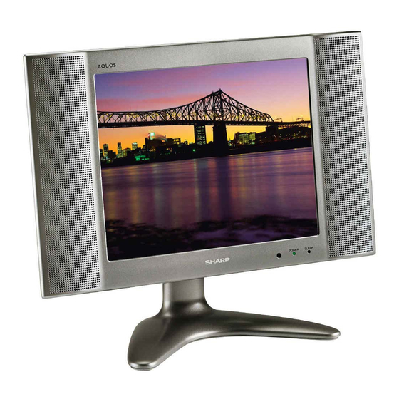
LCD COLOR TELEVISION
LC-15B2UA
LC-15B2UB
MODELS
OUTLINE
CONTENTS
Page
Ë ANALOG UNIT .......................................... 42
Ë INVERTER UNIT ....................................... 46
» PRINTED WIRING BOARD ASSEMBLIES ..... 47
Ë ELECTRICAL PARTS ................................ 59
Ë DIGITAL UNIT ............................................ 59
Ë ANALOG UNIT .......................................... 63
Ë CONTROL UNIT ........................................ 66
Ë RC/LED UNIT ............................................ 66
Ë INVERTER UNIT ....................................... 66
Ë CABINET AND MECHANICAL PARTS ..... 67
Ë ACCESSORIES PARTS ............................ 69
Ë PACKING PARTS ...................................... 69
» PACKING OF THE SET ................................... 70
This document has been published to be used for
after sales service only.
The contents are subject to change without notice.
LC-15B2UA
LC-15B2UB
S52I9LC15B2UB
Page
Advertisement
Table of Contents

Related Manuals for Sharp LC-15B2UA


Summary of Contents for Sharp LC-15B2UA
-
Page 1: Table Of Contents
OUTLINE The 15" LCD panel used in the LC-15B2UA has been redesigned as from the April production. Accordingly, the circuitry and the adjustment procedures have been partially changed. - Page 2 LC-15B2UA LC-15B2UB LIST OF CHANGED PARTS (Model : LC-15B2UA) Rel. No. Description Current (–2002. Mar.) New (2002. Apr. –) Note PRINTED WIRING BOARD ASSEMBLIES DIGITAL UNIT DUNTKA670FE11 DUNTKA670FE51 LCD PANEL 15"LCD Panel RLCDTA003WJZZ RLCDTA013WJZZ DIGITAL UNIT R1024 Resistor VRS-CY1JF000JY VRS-CY1FJ123FY...
- Page 3 LC-15B2UA LC-15B2UB » List of adjustment mode menu Page Items DUNTKA670FE11 DUNTKA670FE51 INCH SIZE V255 V255 BIAS V235 V235 BIAS V176 V176 BIAS V112 V112 BIAS V64 BIAS V32 BIAS V21 BIAS V17 BIAS V7 BIAS V0 BIAS PAL-M TV COLOR...
-
Page 4: Important Service Safety Precaution
LC-15B2UA LC-15B2UB IMPORTANT SERVICE SAFETY PRECAUTION Ë Service work should be perfomed only by qualified service technicians who are thor- oughly familiar with all safety checks and the servicing guidelines which follow: • Use an AC voltmeter having with 5000 ohm per volt, or... - Page 5 LC-15B2UA LC-15B2UB PRECAUTIONS A PRENDRE LORS DE LA REPARATION Ë Ne peut effectuer la réparation qu' un technicien spécialisé qui s'est parfaitement accoutumé à toute vérification de sécurité et aux conseils suivants. • Utiliser un voltmètre CA d'une sensibilité d'au moins AVERTISSEMENT 5000Ω/V pour mesurer la chute de tension en travers...
- Page 6 LC-15B2UA LC-15B2UB Ë Precautions for using lead-free solder 1 Employing lead-free solder “DIGITAL PWB” of this model employs lead-free solder. The LF symbol indicates lead-free solder, and is attached on the PWBs and service manuals. The alphabetical character following LF shows the type of lead- free solder.
-
Page 7: Specifications
LC-15B2UA LC-15B2UB SPECIFICATIONS Items ............15" LCD COLOR TV, Model: LC-15B2UA/B LCD panel ................. 15" ASV & BLACK-TFT LCD Number of dots ................. 921,600 dots VGA Video color system ......N358/N443/PAL/PAL-M/PAL-N/SECAM/PAL-60 TV Function Destination ..................USA/Latin A/Twn TV-Standard (CCIR) ..............NTSC/PAL-M/PAL-N TV-Tuning System ................... -
Page 8: Operation Manual
LC-15B2UA LC-15B2UB OPERATION MANUAL Main unit (front view) Terminals Remote Control... -
Page 9: Dimensions
LC-15B2UA LC-15B2UB DIMENSIONS / 484 / 305.3 / 301.6 / 98.8 / 61.1 / 27 / 149.5 / 48.5 / 198 (Unit: Inch/mm) -
Page 10: Removing Of Major Parts
LC-15B2UA LC-15B2UB REMOVING OF MAJOR PARTS 1. Remove two Rear covers. 2. Remove the Table stand fixing screws (4 pcs.). 3. Remove the Rear cabinet fixing screws (10 pcs.) and detach the cabinet. 4. Push on the hooks of the Rear cabinet, open the cabinet and detach eight hooks, and then detach the Rear cabinet. - Page 11 LC-15B2UA LC-15B2UB 6. Remove the Digital PWB fixing screws (3 pcs.). 7. Remove the Inverter PWB fixing screw (2 pcs.). 8. Remove the Analog PWB fixing screws (4 pcs.). 9. Detach the chassis frame cover. 10. Remove the RC/LED PWB fixing screws (2 pcs.).
- Page 12 LC-15B2UA LC-15B2UB » Precautions in handling the LCD panels 1. Work in a clean room (with humidities below 50%). 2. Be sure to wear an anti-static armband. 3. Handle the panels on an electroconductive mat. 4. Be careful not to fall, shake and shock the panels.
-
Page 13: Adjusting Procedure Of Each Section
LC-15B2UA LC-15B2UB ADJUSTING PROCEDURE OF EACH SECTION The best adjustment is made before shipping. If any position deviation is found or after part replace is performed, adjust as follows. 1. Preparation for Adjustments (1) Use the exclusive-use AC adapter or stable DC power supply. - Page 14 LC-15B2UA LC-15B2UB 4. Adjustments Adjustment Adjusting conditions Adjusting method B+ Adjustment 1. Connect the DC voltmeter to pin (2) of 1. Adjust the "B+ Adj" value to (R3760) P3702. 5.0 ± 0.02V with R3760. * Keep the voltage at pin (2) of P3702 below 5.3V during the adjustment.
- Page 15 LC-15B2UA LC-15B2UB Adjustment Adjusting conditions Adjusting method White balance adjustment 1. Receive the monoscope pattern signal. 2. Adjust the "RCUTOFF" and "BCUTOFF" settings on the page 2 of the adjustment process mode to become the proper white balance. Do not change the "GCUTOFF"...
- Page 16 LC-15B2UA LC-15B2UB 5. Shipping setting list Channel ............................... 2ch Air/Cable ............................. Air Skip Data_CATV ..........................All Skip Skip Data_AIR ............................ All Skip Volume ..............................20 Picture ..............................30 Tint ..............................0 Color ..............................0 Black Level ............................0 SHARPNESS ............................0 RED-BLUE ............................
- Page 17 LC-15B2UA LC-15B2UB 6. Test patterns in adjustment process mode (1) IC801 (video decoder) test pattern 1-1) Indication of the test pattern Set the screen to AV1, AV2, or component, and do not input a signal. It enters the adjustment process mode. By selecting “TEST PATTERN” on the third line of page 7 and changing the setting value to one of 1 - 6, the test pattern will be displayed.
- Page 18 LC-15B2UA LC-15B2UB (3) Trouble shooting using test patterns Is the test pattern of IC801 displayed normally? Is the test pattern of IC1201 displayed normally? Check the signal output Is the waveform of pins line of IC801, IC801 and (10), (11), (13), (15), (17) its peripheral circuits.
- Page 19 LC-15B2UA LC-15B2UB Descriptions of the terminals of Microprocessor IC (IC2001) RH-iXA154WJN1Q No. Terminal Name Descriptions No. Terminal Name Descriptions V HOLD For closed caption Adjusting procedure For closed caption AV/SY/DY2 CCD input change for US MAINSW Main switch ON “H” / OFF “L”...
- Page 20 LC-15B2UA LC-15B2UB List of the adjustment process mode menu Page Items Initial settings Descriptions Adjustments or descriptions of change Standard settings INCH SIZE Inch size select Adjustment MODEL B2UA Model name SYSTEM AUTO Color system change NTSC PWM FREQ Light control frequency setup...
- Page 21 LC-15B2UA LC-15B2UB Page Items Initial settings Descriptions Adjustments or descriptions of change Video adjustment (VPC setup) [Continued] Comb filter setup Comb filter setup Comb filter setup KILVL 08 Color killer level setup KILHY 05 Color killer hysterysis setup VSYNC DELAY...
- Page 22 LC-15B2UA LC-15B2UB Page Items Initial settings Descriptions Adjustments or descriptions of change Video adjustment (TV · Composite · S-video) [Continued] PAL-M TV COLOR 2800 Color thickness setup (TV) Change value to “2600” PAL-M AV COLOR 2800 Color thickness setup (Composite, S-video) Change value to “2600”...
- Page 23 LC-15B2UA LC-15B2UB Page Items Initial settings Descriptions Adjustments or descriptions of change LCD controller setup (PAL) / Closed caption setup [continued] PAL 06 Horizontal display position PAL 07 Vertical display position PAL 08 UV data phase delay PAL 09 Panel clock adjustment...
-
Page 24: Trouble Shooting Table
LC-15B2UA LC-15B2UB TROUBLE SHOOTING TABLE No Power (Power LED indicator still in red) Go to the adjustment process mode. INCH SIZE MODEL B2UA SYSTEM AUTO NTSC PWM FREQ PAL PWM FREQ NTSC PWM DUTY PAL PWM DUTY TV GAIN ERROR NO RESET... - Page 25 LC-15B2UA LC-15B2UB TROUBLE SHOOTING TABLE (Continued)
- Page 26 LC-15B2UA LC-15B2UB TROUBLE SHOOTING TABLE (Continued)
- Page 27 LC-15B2UA LC-15B2UB TROUBLE SHOOTING TABLE (Continued)
-
Page 28: Chassis Layout
LC-15B2UA LC-15B2UB CHASSIS LAYOUT DIGITAL Unit (Side-A) DIGITAL Unit (Side-B) - Page 29 LC-15B2UA LC-15B2UB INVERTER Unit CONTROL Unit RC/LED Unit ANALOG Unit...
-
Page 30: Block Diagram
LC-15B2UA LC-15B2UB BLOCK DIAGRAM ANALOG UNIT TV-V TUNER TU3201 SIF-AMP. Q3201 Q3202 SY, SC AV 1 TV-V S-VIDEO VIDEO L1, R1 INPUT SWITCH IC402 V2/VO AV 2 AUDIO VIDEO L2, R2 INPUT IN/OUT IN/OUT OUTPUT SWITCH SWITCH VOUT IC3501 Q3501-Q3505... - Page 31 LC-15B2UA LC-15B2UB DIGITAL UNIT SY, SC ITCH C402 VIDEO DECODER CONTROLLER (VPC) IC1201 IC801 PANEL FIFO IC1202 BUFFER RATER. Q402 C401 GRADUATION 3.3V REG. POWER FOR IC702 IC1102-IC1108 CK, VD, HD, OSD-RGB IC1110 CVIN IC1112 IC1114 3 WIRE IC1115 CSYNC...
-
Page 32: Description Of Schematic Diagram
LC-15B2UA LC-15B2UB DESCRIPTION OF SCHEMATIC DIAGRAM VOLTAGE MEASUREMENT CONDITION: CAUTION: 1. Voltages at test points are measured on exclusive This circuit diagram is original one, therefore there may be a AC adaptor and the stable supply voltage of AC slight difference from yours. -
Page 33: Schematic Diagramë Control And Rc/Led Unit
LC-15B2UA LC-15B2UB SCHEMATIC DIAGRAM Ë CONTROL and RC/LED Unit... -
Page 34: Ë Digital Unit
LC-15B2UA LC-15B2UB Ë DIGITAL Unit-1/4... - Page 35 LC-15B2UA LC-15B2UB...
- Page 36 LC-15B2UA LC-15B2UB Ë DIGITAL Unit-2/4...
- Page 37 LC-15B2UA LC-15B2UB...
- Page 38 LC-15B2UA LC-15B2UB Ë DIGITAL Unit-3/4...
- Page 39 LC-15B2UA LC-15B2UB...
- Page 40 LC-15B2UA LC-15B2UB Ë DIGITAL Unit-4/4...
- Page 41 LC-15B2UA LC-15B2UB...
-
Page 42: Ë Analog Unit
LC-15B2UA LC-15B2UB Ë ANALOG Unit-1/2... - Page 43 LC-15B2UA LC-15B2UB...
- Page 44 LC-15B2UA LC-15B2UB Ë ANALOG Unit-2/2...
- Page 45 LC-15B2UA LC-15B2UB...
-
Page 46: Ë Inverter Unit
LC-15B2UA LC-15B2UB Ë INVERTER Unit... -
Page 47: Printed Wiring Board Assemblies
LC-15B2UA LC-15B2UB PRINTED WIRING BOARD ASSEMBLIES ANALOG Unit (Side-A) - Page 48 LC-15B2UA LC-15B2UB DIGITAL Unit (Side-B)
- Page 49 LC-15B2UA LC-15B2UB DIGITAL Unit (Side-A)
- Page 50 LC-15B2UA LC-15B2UB CONTROL Unit (Side-A) CONTROL Unit (Side-B) INVERTER Unit (Side-A) RC/LED Unit (Side-A)
- Page 51 LC-15B2UA LC-15B2UB R6503 Q6502 FH6501 FH6500 Q6500 Q6501 C6501 R6507 C6510 C6500 R6506 C6508 C6507 T6503 T6502 C6506 INVERTER Unit (Chip Parts Side)
- Page 52 LC-15B2UA LC-15B2UB C701 P2003 D701 P2004 C702 R714 R705 C7104 Q2005 Q2006 R2057 R2024 R419 C409 C414 R415 R2033 R2062 L402 C408 C413 R414 L401 C411 C2020 R2055 R422 C412 R416 FB7105 R2026 R2036 R425 R2044 R2045 IC2001 FL401 R2017...
- Page 53 LC-15B2UA LC-15B2UB P2003 C908 R1247 R712 C1208 R2060 C1217 L901 R2057 R2068 R1018 C1228 R2062 D1206 D1205 C1234 R2054 R2002 IC2001 R1257 R2063 R2028 R1258 R2031 R2032 R2051 R2011 C909 C821 R2029 P2001 C1205 R918 R916 C826 R1223 R1218 C706...
- Page 54 LC-15B2UA LC-15B2UB D1211 D902 FB903 FB901 IC901 R1237 R1239 R911 R1249 R1248 R1240 D1209 D901 R910 Q1204 R1230 R1251 R1250 TP2005 C1233 R2059 IC2004 IC2002 R1225 R1254 TP2003 R2058 C840 C812 R2016 C1204 R831 R1256 R812 R837 R838 C810 IC2003...
- Page 55 LC-15B2UA LC-15B2UB IC703 R715 R2066 D2005 R2065 R2064 R2052 R2049 TP2001 R2003 TP2002 TP2006 R2030 R413 TP2007 TP2009 IC2002 R407 R411 FB7102 TP2003 R406 R7113 C2002 C406 C2001 R402 C405 FB7101 C407 R410 R409 C2003 R7705 R7114 IC401 C7121 C401...
- Page 56 LC-15B2UA LC-15B2UB P3704 R3756 R3701 FH3701 FH3702 FH3703 FH3704 C3700 D3703 FB3701 C3711 R372 FB3709 R3717 C3703 R3768 R3706 IC3701 TU3201 R3703 R3707 C3706 R3708 R3705 C3705 R3711 C3707 R3709 R3760 C3719 R3727 R3732 C3716 L3704 Q3704 R3762 Q3707 R3746...
- Page 57 LC-15B2UA LC-15B2UB P3602 P3601 P3500 P3502P3501 D3601 D3602 C3607 R3757 R3605 C3606 Q3602 C3603 C3605 R3604 R3608 R3607 C3602 C3604 C3601 Q3601 D3605 C3600 D3703 R3718 C3608 D3606 D3604 FB3701 C3609 C3711 C3713 D3607 R3721 R3720 R3722 FB3709 R3610 FB3700...
- Page 58 LC-15B2UA LC-15B2UB P4005 SW4008 D4013 R4021 C4018 SW4007 R4006 R4005 SW4002 SW4003 Q4003 R4011 R4012 R4030 R4031 SW4004 RC/LED Unit (Chip Parts Side) SW4006 D4008 D4009 D4010 P4004 CONTROL Unit (Chip Parts Side)
-
Page 59: Parts List
4. DESCRIPTION in USA: Contact your nearest SHARP Parts Distributor to order. in CANADA: Contact SHARP Electronics of Canada Limited For location of SHARP Parts Distributor, Please call Toll- Phone (416) 890-2100 Free; 1-800-BE-SHARP MARK: SPARE PARTS-DELIVERY SECTION MARQUE: SECTION LIVRAISON DES PIECES DE RECHANGE Ref. - Page 60 LC-15B2UA LC-15B2UB Ref. No. Part No. Description Code Ref. No. Part No. Description Code DUNTKA670FE51 C817 VCKYTV1CF105Z Ceramic C818 RC-KZ1025CEZZ Ceramic DIGITAL UNIT (Contineud) C819 RC-KZ1025CEZZ Ceramic C820 VCKYCY1EF104Z J 0.1 Ceramic D1107 VHD1SS250//1E J Diode C821 VCEAPF1CN107M J 100...
- Page 61 LC-15B2UA LC-15B2UB Ref. No. Part No. Description Code Ref. No. Part No. Description Code DUNTKA670FE51 R807 VRS-CY1JF750J J 75 1/16W Metal Oxide R808 VRS-CY1JF750J J 75 1/16W Metal Oxide DIGITAL UNIT (Contineud) R809 VRS-CY1JF750J J 75 1/16W Metal Oxide R810...
- Page 62 LC-15B2UA LC-15B2UB Ref. No. Part No. Description Code Ref. No. Part No. Description Code DUNTKA670FE51 R1234 VRS-CY1JF472J J 4.7k 1/16W Metal Oxide R1235 VRS-CB1JF473J J 47k 1/16W Metal Oxide DIGITAL UNIT (Contineud) R1236 VRS-CB1JF473J J 47k 1/16W Metal Oxide R1237 VRS-TX2HF472J J 4.7k 1/2W...
-
Page 63: Ë Analog Unit
LC-15B2UA LC-15B2UB Ref. No. Part No. Description Code Ref. No. Part No. Description Code DUNTKB128DE02 L3500 VP-1M101J7R7N J Peaking 100µH L3700 RCiLC0130CEZZ J Coil ANALOG UNIT L3702 RCiLC0130CEZZ J Coil L3703 RCiLC0057CEZZ J Coil TUNER TRANSFORMER NOTE: THE PARTS HERE SHOWN ARE SUPPLIED AS AN ASSEMBLY BUT NOT INDEPENDENTLY. - Page 64 LC-15B2UA LC-15B2UB Ref. No. Part No. Description Code Ref. No. Part No. Description Code DUNTKB128DE02 R3207 VRS-CY1JF102J J 1k 1/16W Metal Oxide R3208 VRS-CA1JF561J J 560 1/16W Metal Oxide ANALOG UNIT (Contined) R3306 VRS-CY1JF000J 1/16W Metal Oxide R3310 VRS-CY1JF000J 1/16W Metal Oxide...
- Page 65 LC-15B2UA LC-15B2UB Ref. No. Part No. Description Code Ref. No. Part No. Description Code DUNTKB128DE02 R3750 VRS-CY1JF391J J 390 1/16W Metal Oxide R3751 VRS-TV1JD103J J 10k 1/16W Metal Oxide ANALOG UNIT (Contined) R3752 VRS-CY1JF102J J 1k 1/16W Metal Oxide R3753 VRS-TX2HF000J...
-
Page 66: Ë Control Unit
LC-15B2UA LC-15B2UB Ref. No. Part No. Description Code Ref. No. Part No. Description Code DUNTKB129DE02 DUNTKB131DE02 CONTROL UNIT INVERTER UNIT DIODES TRANSISTORS D4008 RH-EX1283CEZZ J Zener Diode, 18V Q6500 VSFZT1053A/-1 J FZT1053A D4009 RH-EX1271CEZZ J Zener Diode, 12V Q6501 VSFZT1053A/-1... - Page 67 PSPAH0694CEZZ J Spacer, x2 5-16 XBBSD30P05000 J Screw, x2 PSPAH0695CEZZ J Spacer, x2 QEARZ0047CEZZ J Grounding Part GCOVA2105CEKA J Chasis Frame(LC-15B2UA) AP RSP-Z0131CEZZ J Speaker, Left GCOVA2105CEKB J Chasis Frame(LC-15B2UB) AP RSP-Z0132CEZZ J Speaker, Right JBTN-2066CEKA J Power Button 1-10...
-
Page 68: Ë Cabinet And Mechanical Parts
LC-15B2UA LC-15B2UB CABINET AND MECHANICAL PARTS 1-10 CONTROL Unit DIGITAL Unit 1-11 INVERTER Unit 1-10 1-11 1-12 ANALOG Unit 5-11 RC/LED Unit 5-16 5-10 5-15 5-14 5-15 3-11 3-12 3-16 3-13 3-10 3-16 5-12 3-15 3-14 3-12 3-15 3-12 3-12... -
Page 69: Ë Accessories Parts
LC-15B2UA LC-15B2UB Ref. No. Part No. Description Code Ref. No. Part No. Description Code PACKING PARTS SUPPLIED ACCESSORIES (NOT REPLACEMENT ITEM) LHLDW0109CESA J Cable Clamp, x2 SPAKC5678CEZZ – Packing Case — (LC-15B2UA) (LC-15B2UA) LHLDW0109CESB J Cable Clamp, x2 SPAKCA114WJZZ – Packing Case —... -
Page 70: Packing Of The Set
LC-15B2UA LC-15B2UB PACKING OF THE SET Reinforcement Pad (SPAKF0575CEZZ) Operation Manual (LC-15B2UA) (TiNS-7603CEZZ) Operation Manual (LC-15B2UB) (TiNS-A181WJZZ) Polyethylene Bag, Cable Clamp (2pcs.) for Accessories (LHLDW0109CESA:LC-15B2UA) (SSAKA0160CEZZ) (LHLDW0109CESB:LC-15B2UB) Battery (2pcs.) AC Adapter (UADP-0242CEPZ) AC Cord (QACCD3097CEPA) Antenna Cable (QCNWG0003CEPA) Remote Control... - Page 71 LC-15B2UA LC-15B2UB...
- Page 72 LC-15B2UA LC-15B2UB COPYRIGHT © 2002 BY SHARP CORPORATION ALL RIGHTS RESERVED. No part of this publication may be reproduced, stored in a retrieval system, or transmitted in any form or by any means, electronic, mechanical, photocopying, recording, or otherwise, without prior written permission of the publisher.