Table of Contents
Advertisement
Quick Links
SIMATIC
ET 200SP HA
IM 155-6 PN HA
Equipment Manual
6DL1193-6AR00-0AA0;6DL1193-6AG00-0AA0;
6DL1193-6AG20-0AA0;6DL1193-6AG40-0AA0;
6DL1193-6AF00-0AA0;6DL1155-6AU00-0PM0;
6DL1155-6AU00-0EM0
09/2021
A5E39262148-AE
Security information
Preface
Product overview
Terminal
Parameters
Behavior of the device name
Displays and interrupts
Technical specifications
Diagnostic messages
1
2
3
4
5
6
7
8
A
Advertisement
Table of Contents

Related Manuals for Siemens ET 200SP HA


Summary of Contents for Siemens ET 200SP HA
- Page 1 Security information Preface Product overview SIMATIC Terminal ET 200SP HA IM 155-6 PN HA Parameters Behavior of the device name Equipment Manual Displays and interrupts Technical specifications Diagnostic messages 6DL1193-6AR00-0AA0;6DL1193-6AG00-0AA0; 6DL1193-6AG20-0AA0;6DL1193-6AG40-0AA0; 6DL1193-6AF00-0AA0;6DL1155-6AU00-0PM0; 6DL1155-6AU00-0EM0 09/2021 A5E39262148-AE...
- Page 2 Note the following: WARNING Siemens products may only be used for the applications described in the catalog and in the relevant technical documentation. If products and components from other manufacturers are used, these must be recommended or approved by Siemens. Proper transport, storage, installation, assembly, commissioning, operation and maintenance are required to ensure that the products operate safely and without any problems.
-
Page 3: Table Of Contents
Table of contents Security information..........................5 Preface ..............................7 Product overview ........................... 9 Interface module ......................... 9 Accessories ........................10 Fail-safe I/O modules in the I/O device ................11 3.3.1 Response times for the fail-safe modules ................11 3.3.2 Redundancy switchover times for the fail-safe modules ............12 Shared Device ........................ - Page 4 Table of contents 7.4.2 Example for error display....................33 LED display for setup error....................33 Interrupts .......................... 34 Technical specifications ........................35 Technical specifications ...................... 35 Diagnostic messages ........................... 45 Diagnostics alarms ......................45 Maintenance events......................46 Diagnostics of a shared device.................... 47 Tables Table A-1 Diagnostic messages, their meaning and possible remedies.............
-
Page 5: Security Information
Use of product versions that are no longer supported, and failure to apply latest updates may increase customer’s exposure to cyber threats. To stay informed about product updates, subscribe to the Siemens Industrial Security RSS Feed under https://www.siemens.com/industrialsecurity. - Page 6 Security information IM 155-6 PN HA Equipment Manual, 09/2021, A5E39262148-AE...
-
Page 7: Preface
BA LC/FC 6DL1193-6AG40-0AA0 It supplements the system manual of the ET 200SP HA Distributed I/O System. Functions that generally relate to the system are described in this manual. The information in this product manual, system manual and function manual enables you to commission the ET 200SP HA distributed I/O system. - Page 8 Preface IM 155-6 PN HA Equipment Manual, 09/2021, A5E39262148-AE...
-
Page 9: Product Overview
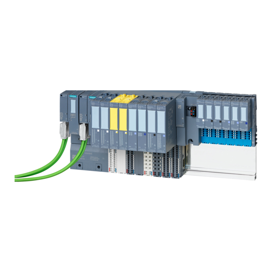
The IM 155‑6 PN HA, together with the carrier and BusAdapter, forms the interface of the ET 200SP HA. The interface is used for communication between the CPU and the connected ET 200SP HA I/O modules via PROFINET IO. In addition to the technical specifications, this module has the following properties: •... -
Page 10: Accessories
Product overview 3.2 Accessories Description The interface module consists of the following components: ① ⑧ Module type and designation MAC address (specific address for this exact module) ② ⑨ LED for operating state Function status and firmware version ③ ⑩ LED for diagnostics Article number ④... -
Page 11: Fail-Safe I/O Modules In The I/O Device
Product overview 3.3 Fail-safe I/O modules in the I/O device Description The following accessories are available: • BusAdapter Type Article number Function BA 2×RJ45 6DL1193-6AR00-0AA0 Adapter for Ethernet cable with RJ45 connector BA 2×FC 6DL1193-6AF00-0AA0 Adapter for direct connection of the Fast Connect bus cable BA 2xLC 6DL1193-6AG00-0AA0... -
Page 12: Redundancy Switchover Times For The Fail-Safe Modules
Redundancy switchover times for the fail-safe modules Definition With redundant operation of the interface modules of the ET 200SP HA, you should expect a switchover time to the active communication channel of a maximum of 500ms. During this time, the input and output values may be frozen during a redundancy switchover. - Page 13 1. Open one of the previously created stations in the hardware configuration in the configuration tool. 2. Configure a PROFINET IO device ET 200SP HA (IM 155-6 PN HA) with its own I/O modules. 3. Copy the created IO device.
-
Page 14: Shared Device In Different Step 7 Projects
2. Open the station of the IO controller "CPU1" in the hardware configuration in the configuration tool. 3. Configure a PROFINET IO device ET 200SP HA (IM 155-6 PN HA) with its own I/O modules. 4. Write down the exact configuration of the IO device ET 200SP HA created this way. - Page 15 Product overview 3.4 Shared Device 8. Configure the PROFINET IO device ET 200SP HA with the exact same configuration as that of the IO device ET 200SP HA in the project "Shared-Device-1" in the station "CPU1" (notes from step 4.).
-
Page 16: Useful Information On Using Shared Devices
Product overview 3.4 Shared Device Bandwidth reservation in STEP 7 When configuring shared devices in different projects, STEP 7 needs information on the locations of use of the shared device to ensure correct calculation of the bandwidth. Make the settings listed below in both projects: 1. -
Page 17: Io Device As Shared Device
Product overview 3.4 Shared Device CiR (Configration in RUN) disabled When the "Shared Device" function is enabled, you can only make configuration changes when the CPU is in STOP. Time stamping The use of shared devices with the "Time stamping" function of signal changes has the following effects: •... -
Page 18: Overview Of Access Types
Product overview 3.4 Shared Device Description The following access types are available: • Full access (Page 18) • No access (Page 18) 3.4.7 Overview of access types 3.4.7.1 Full access Definition The IO controller has full access to the submodule and its logical address. Description The following rights of the IO controller are available: •... -
Page 19: Configuration Limit For Io Devices
Maximum of 1000 bytes each 1 redundant IO controller and Maximum of 360 bytes each 1 additional IO controller System redundancy R1 Maximum of 1440 bytes each See also Online Support (https://support.industry.siemens.com/cs/ww/en/view/109760425) IM 155-6 PN HA Equipment Manual, 09/2021, A5E39262148-AE... - Page 20 Product overview 3.5 Configuration limit for IO devices IM 155-6 PN HA Equipment Manual, 09/2021, A5E39262148-AE...
-
Page 21: Terminal
1L+ and 2L+ as well as 1M and 2M are bridged internally. Maximum 10 A permitted. Note Pin assignment BusAdapter You can find information on pin assignment of the BusAdapter under: https://support.industry.siemens.com/cs/ww/en/view/109773801 (https:// support.industry.siemens.com/cs/ww/en/view/109773801) IM 155-6 PN HA Equipment Manual, 09/2021, A5E39262148-AE... -
Page 22: Schematic Circuit Diagram
Terminal 4.2 Schematic circuit diagram Schematic circuit diagram Schematic circuit diagram A block diagram contains the schematic representation of individual function blocks. Description The block diagram of the IM 155‑6 PN HA interface module is as follows: ① Switch Supply voltage (24 V DC) ②... -
Page 23: Parameters
Parameters Definition The parameter assignment specifies the properties of the IO device. Description You configure the ET 200SP HA on a CPU 410 as of FW V8.2. IM 155-6 PN HA Equipment Manual, 09/2021, A5E39262148-AE... - Page 24 Parameters IM 155-6 PN HA Equipment Manual, 09/2021, A5E39262148-AE...
-
Page 25: Behavior Of The Device Name
Behavior of the device name The device name of the distributed I/O device is saved at the following locations when transferring the device name to the distributed I/O: • In the BusAdapter • In the interface of the distributed I/O device (e.g. interface module or I/O device itself) Note Replacing a BusAdapter (removing/inserting) Removing/inserting the BusAdapter under voltage is prohibited. - Page 26 Behavior of the device name IM 155-6 PN HA Equipment Manual, 09/2021, A5E39262148-AE...
-
Page 27: Displays And Interrupts
Displays and interrupts Status and error displays Definition The LED displays are status and error indicators. Diagnostics messages and maintenance events, as well as their possible causes or solutions, are described in the diagnostics messages and maintenance events. Diagnostics alarms (Page 45) IM 155-6 PN HA Equipment Manual, 09/2021, A5E39262148-AE... -
Page 28: Leds
Displays and interrupts 7.2 LEDs Description The following picture shows the LED indicators of the IM 155-6 PN HA: SIEMENS ① RN LED (Page 28) (green) ② ER LED (Page 29) (red) ③ MT LED (Page 30) (yellow) ④ ACT LED (Page 30) (green) ⑤... -
Page 29: Er Led
Impermissible configuration states You can find information about the hardware configuration of the ET 200SP HA in the system manual ET 200SP HA Distributed I/O System; System Planning, Hardware Configuration. Parameter assignment error in the I/O Evaluate the display of the module information in HW-Konfig and elim‐... -
Page 30: Mt Led
Displays and interrupts 7.2 LEDs 7.2.3 MT LED Definition The MT LED provides maintenance information. Description The MT LED indicates the following maintenance status: MT LED Meaning Maintenance is not required. Maintenance is required, meaning that at least one maintenance event has occurred. Note Redundant interface modules (IM): Maintenance LED and ER LED are illuminated on both If the station was configured with V1.0 in HW Config and both IMs have different firmware... -
Page 31: Pwr Led
Displays and interrupts 7.2 LEDs Description The ACT LED indicates the following status: ACT LED Meaning (only relevant for IO device with redundant IM) There is no active data exchange with the I/O modules via this IM. There is an active data exchange with the I/O modules via this IM. The partner IM can apply the data exchange. -
Page 32: Useful Information On Error Indicators
Displays and interrupts 7.4 Error display Description The LK LED indicates the following status: Meaning Remedy LK1/LK2 There is no Ethernet connection between the PROFINET IO inter‐ Check whether the bus cable to the face of your PROFINET device and a communication partner (e.g. IO switch/IO controller is interrupted. -
Page 33: Example For Error Display
Cause of error Solution (MAINT) Check the configuration of the • No server module ET 200SP HA. • Interruptions on the backplane • Short-circuit on backplane bus Note The following LEDs indicate a short-circuit in the backplane bus supply or in the bus connection supply: •... -
Page 34: Interrupts
Displays and interrupts 7.6 Interrupts Interrupts Definition A diagnostics interrupt is an alarm that reports activated events of a device status to the system operator with the appropriate operating authorization (maintenance and service). Description The interface module supports diagnostics interrupts: The IM 155-6 PN HA generates a diagnostic interrupt for the following events: •... -
Page 35: Technical Specifications
Technical specifications Technical specifications Article number 6DL1155-6AU00-0PM0 General information Product type designation IM 155-6 PN HW functional status FS03 Firmware version V1.1 Vendor identification (VendorID) 02AH Device identifier (DeviceID) 030FH Product function Yes; I&M0 to I&M3 • I&M data Engineering with •... - Page 36 Technical specifications 8.1 Technical specifications Article number 6DL1155-6AU00-0PM0 256 byte • Address space per module, max. Address space per station 1 440 byte; 1 440 bytes R1 and S1 without CiR, • Address space per station, max. otherwise 1 000 bytes Hardware configuration Integrated power supply Yes;...
- Page 37 Technical specifications 8.1 Technical specifications Article number 6DL1155-6AU00-0PM0 Yes; red LED • ERROR LED Yes; Yellow LED • MAINT LED Yes; green LED • ACT LED Yes; green PWR LED • Monitoring of the supply voltage (PWR-LED) Yes; 2x green link LEDs on BusAdapter •...
- Page 38 Technical specifications 8.1 Technical specifications Article number 6DL1155-6AU00-0EM0 General information Product type designation IM 155-6 PN Firmware version V1.0 Vendor identification (VendorID) 02AH Device identifier (DeviceID) 0309H Product function Yes; I&M0 to I&M3 • I&M data Engineering with V8.0 • SPPA-T3000 can be configured/integrated from version Configuration control...
- Page 39 Technical specifications 8.1 Technical specifications Article number 6DL1155-6AU00-0EM0 Yes; compatible BusAdapters: BA 2x RJ45, BA 2x FC, • BusAdapter (PROFINET) BA 2x LC, BA LC/RJ45, BA LC/FC Protocols • PROFINET IO Device • Open IE communication Yes; as MRP client •...
- Page 40 Technical specifications 8.1 Technical specifications Supplemental information on the address space for each operating mode The size of user data attachment of the I/O modules depends on the type (1 byte if only input or output address space are allocated, or 2 bytes if both address spaces are allocated). You can determine the allocated address space from the technical specifications in the manuals of the I/ O modules.
- Page 41 Technical specifications 8.1 Technical specifications Article number 6DL1193-6AG00-0AA0 General information Product type designation BA 2xLC Interfaces Number of PROFINET interfaces 1; 2 ports (switch) LC Multimode Glass Fibre Supports protocol for PROFINET IO • Number of LC ports Cable length –...
- Page 42 Technical specifications 8.1 Technical specifications Article number 6DL1193-6AF00-0AA0 General information Product type designation BA 2xFC Interfaces Number of PROFINET interfaces 1; 2 ports (switch) FC Supports protocol for PROFINET IO • Number of FC (FastConnect) connections Cable length 100 m –...
- Page 43 Technical specifications 8.1 Technical specifications Article number 6DL1193-6AG20-0AA0 General information Product type designation BA LC/RJ45 Interfaces Number of PROFINET interfaces 1; 2 ports (switch) LC / RJ45 Supports protocol for PROFINET IO • Number of RJ45 ports 1; Wavelength of 1 270 ... 1 380 nm, corresponds •...
- Page 44 Technical specifications 8.1 Technical specifications Article number 6DL1193-6AG40-0AA0 General information Product type designation BA LC/FC Interfaces Number of PROFINET interfaces 1; 2 ports (switch) LC / FC Supports protocol for PROFINET IO • Number of FC (FastConnect) connections 1; Wavelength of 1 270 ... 1 380 nm, corresponds •...
-
Page 45: Diagnostic Messages
Verify that the server module is Station Stop – No tion present during power-up of correctly installed in the rack. server module an ET 200SP HA station. Configuration error: 0x0602 0x0691 Configura‐ The installed terminal block Ensure that a matching termi‐... -
Page 46: Maintenance Events
Diagnostic messages A.2 Maintenance events Diagnostics mes‐ Channel Exten‐ Assignment Meaning Remedy sage error ded chan‐ type nel error (CET) type (CET) Redundancy error: 0x0630 0x06D0 Redundant Errors in the redundancy of Replace the partner interface Failure in the partner modules the interface module are sig‐... -
Page 47: Diagnostics Of A Shared Device
Diagnostic messages A.3 Diagnostics of a shared device Maintenance messages have no direct effect on the module function. Table A-2 Maintenance messages, their meaning and possible remedies Maintenance mes‐ Channel Extended Assignment Meaning / Cause Remedy sage error channel type error (CET) type... - Page 48 Diagnostic messages A.3 Diagnostics of a shared device IM 155-6 PN HA Equipment Manual, 09/2021, A5E39262148-AE...