Advertisement
Quick Links
Shop
Manual
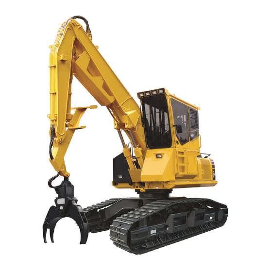
PC290LL
LOG LOADER
ROAD BUILDER
SERIAL NUMBERS
ENGINE
This material is proprietary to Komatsu America Corp. and is not to be reproduced, used, or disclosed except in
accordance with written authorization from Komatsu America Corp.
It is our policy to improve our products whenever it is possible and practical to do so. We reserve the right to
make changes or improvements at any time without incurring any obligation to install such changes on products
sold previously.
Due to this continuous program of research and development, revisions may be made to this publication. It is
recommended that customers contact their distributor for information on the latest revision.
April 2018
PC290LL-11 A29501
6D107E-3
-11
and up
Copyright 2018 Komatsu
Printed in U.S.A.
Komatsu America Corp.
CEBM031404
Advertisement

Related Manuals for Komatsu PC290LL-11


Summary of Contents for Komatsu PC290LL-11
- Page 1 6D107E-3 ENGINE This material is proprietary to Komatsu America Corp. and is not to be reproduced, used, or disclosed except in accordance with written authorization from Komatsu America Corp. It is our policy to improve our products whenever it is possible and practical to do so. We reserve the right to make changes or improvements at any time without incurring any obligation to install such changes on products sold previously.
- Page 2 Find manuals at https://best-manuals.com...
- Page 3 00 INDEX AND FOREWORD PC290LL-11 00-1 Find manuals at https://best-manuals.com...
- Page 4 SYSTEM OPERATING LAMP SYSTEM ..................10-36 BATTERY DISCONNECT SWITCH ....................10-37 ENGINE SYSTEM ..........................10-38 LAYOUT DRAWING OF ENGINE SYSTEM ................... 10-38 ENGINE CONTROL SYSTEM ....................... 10-40 AUTO-DECELERATION SYSTEM ....................10-43 ENGINE AUTOMATIC WARM-UP SYSTEM .................. 10-45 00-2 PC290LL-11 Find manuals at https://best-manuals.com...
- Page 5 STANDARD VALUE TABLE FOR ENGINE ..................... 20-8 STANDARD VALUE TABLE FOR ENGINE: PC290LL-11..............20-8 STANDARD VALUE TABLE FOR MACHINE..................20-12 STANDARD VALUE TABLE FOR MACHINE: PC290LL-11 ............20-12 POSTURE OF MACHINE FOR MEASURING PERFORMANCE AND MEASUREMENT PROCEDURE..............................20-25 STANDARD VALUE TABLE FOR ELECTRICAL ................... 20-31...
- Page 6 METHOD FOR STARTING UP KOMTRAX TERMINAL ..............30-210 ADJUST REARVIEW CAMERA ANGLE ..................30-215 HANDLE VOLTAGE CIRCUIT OF ENGINE CONTROLLER ............30-218 HANDLE BATTERY DISCONNECT SWITCH ................30-219 TEST DIODES ..........................30-220 Pm CLINIC............................30-221 Pm CLINIC SERVICE ........................30-221 40 TROUBLESHOOTING ..........................40-1 CONTENTS ............................40-2 00-4 PC290LL-11 Find manuals at https://best-manuals.com...
- Page 7 FAILURE CODE [AS10NT] DEF Injector Overheat Caution ............40-210 FAILURE CODE [B@BAZG] Engine Oil Pressure Low ..............40-211 FAILURE CODE [B@BAZK] Eng Oil Level Low ................40-212 FAILURE CODE [B@BCNS] Eng Water Overheat ................40-214 FAILURE CODE [B@BCZK] Eng Water Level Low ...............40-215 PC290LL-11 00-5 Find manuals at https://best-manuals.com...
- Page 8 FAILURE CODE [CA698] Engine Controller Internal Temperature Sensor Low Error....40-314 FAILURE CODE [CA731] Engine Backup Speed Sensor Phase Error ..........40-315 FAILURE CODE [CA778] Engine Backup Speed Sensor Error .............40-317 FAILURE CODE [CA1117] Engine Controller Partial Data Lost Error ..........40-322 00-6 PC290LL-11 Find manuals at https://best-manuals.com...
- Page 9 FAILURE CODE [CA3134] KDPF Outlet Pressure Sensor Low Error..........40-440 FAILURE CODE [CA3135] KDPF Outlet Pressure Sensor In Range Error........40-442 FAILURE CODE [CA3142] SCR Temperature Sensor High Error..........40-445 FAILURE CODE [CA3143] SCR Temperature Sensor Low Error ..........40-446 PC290LL-11 00-7 Find manuals at https://best-manuals.com...
- Page 10 FAILURE CODE [CA3713] DEF Line Heater 1 Voltage High Error ..........40-576 FAILURE CODE [CA3717] SCR Outlet NOx Sensor Voltage Mismatch Error .......40-579 FAILURE CODE [CA3718] Turbo Outlet NOx Sensor Voltage Mismatch Error......40-580 FAILURE CODE [CA3725] Turbo Outlet NOx Sensor Unstable Error..........40-581 00-8 PC290LL-11 Find manuals at https://best-manuals.com...
- Page 11 FAILURE CODE [D811MC] KOMTRAX Malfunction..............40-710 FAILURE CODE [D862KA] GPS Antenna Open Circuit ..............40-711 FAILURE CODE [D8ALKA] System Operating Lamp Open Circuit (KOMTRAX)......40-712 FAILURE CODE [D8ALKB] System Operating Lamp Short Circuit (KOMTRAX) ......40-714 FAILURE CODE [D8AQKR] CAN 2 Defective Communication (KOMTRAX) .........40-716 PC290LL-11 00-9...
- Page 12 FAILURE CODE [DW43KA] Travel Speed Solenoid Open Circuit ..........40-838 FAILURE CODE [DW43KB] Travel Speed Solenoid Short Circuit ..........40-840 FAILURE CODE [DW43KY] Travel Speed Solenoid Hot Short Circuit...........40-842 FAILURE CODE [DW45KA]Swing Parking Brake Solenoid Open Circuit ........40-844 FAILURE CODE [DW45KB] Swing Parking Brake Solenoid Short Circuit ........40-847 00-10 PC290LL-11...
- Page 13 TROUBLESHOOTING OF ELECTRICAL SYSTEM (E-MODE) ............40-955 E-1 ENGINE DOES NOT START (ENGINE DOES NOT CRANK) ..........40-955 E-2 MANUAL PREHEATING SYSTEM DOES NOT WORK............40-961 E-3 AUTOMATIC PREHEATING SYSTEM DOES NOT WORK ............40-964 E-4 WHILE PREHEATING IS WORKING, PREHEATING MONITOR DOES NOT LIGHT UP..40-966 PC290LL-11 00-11...
- Page 14 BRAKE DOES NOT OPERATE ....................40-1011 E-39 ONE-TOUCH POWER MAXIMIZING FUNCTION DOES NOT OPERATE PROPERLY, OR INDI- CATOR NOT DISPLAYED ON MONITOR ................40-1013 E-40 ONE-TOUCH POWER MAXIMIZING FUNCTION IS NOT CANCELLED ......40-1016 E-41 ALARM DOES NOT SOUND DURING TRAVEL ..............40-1017 00-12 PC290LL-11...
- Page 15 H-20 IN COMBINED OPERATION OF SWING AND BOOM RAISE, BOOM RISING SPEED IS LOW ..............................40-1086 H-21 MACHINE DOES NOT TRAVEL STRAIGHT ..............40-1087 H-22 MACHINE IS HARD TO STEER OR TRAVEL POWER IS LOW ........40-1089 H-23 TRAVEL SPEED IS LOW ....................40-1092 PC290LL-11 00-13...
- Page 16 HOW TO READ THIS MANUAL..................... 50-12 COATING MATERIALS LIST......................50-14 SPECIAL TOOLS LIST ........................50-19 SKETCHES OF SPECIAL TOOLS....................50-31 ENGINE AND COOLING SYSTEM....................... 50-36 REMOVE AND INSTALL SUPPLY PUMP ASSEMBLY ..............50-36 REMOVE AND INSTALL INJECTOR ASSEMBLY ................. 50-43 00-14 PC290LL-11...
- Page 17 REMOVE AND INSTALL CONTROL VALVE ASSEMBLY .............50-367 DISASSEMBLE AND ASSEMBLE CONTROL VALVE ASSEMBLY ..........50-380 DISASSEMBLE AND ASSEMBLE WORK EQUIPMENT PPC VALVE ASSEMBLY ......50-386 DISASSEMBLE AND ASSEMBLE TRAVEL PPC VALVE ASSEMBLY ..........50-388 WORK EQUIPMENT..........................50-391 REMOVE AND INSTALL WORK EQUIPMENT ASSEMBLY ............50-391 PC290LL-11 00-15...
- Page 18 MAINTENANCE STANDARD OF 1ST-LINE ATTACHMENT PPC VALVE (WITH EPC VALVE)..60-54 MAINTENANCE STANDARD OF 2ND-LINE ATTACHMENT PPC VALVE ........60-57 MAINTENANCE STANDARD OF SOLENOID VALVE..............60-59 MAINTENANCE STANDARD OF ATTACHMENT CIRCUIT SELECTOR VALVE (FOR HIGH PRES- SURE) ............................60-60 00-16 PC290LL-11...
- Page 19 A-3 TROUBLESHOOTING FOR BLOWER MOTOR SYSTEM (NO AIR COMES OUT OR AIR FLOW IS ABNORMAL).......................... 80-76 A-4 TROUBLESHOOTING FOR FRESH/RECIRC AIR CHANGEOVER........80-78 TROUBLESHOOTING USING GAUGE PRESSURE..............80-80 CONNECTION OF SERVICE TOOL ....................80-83 PRECAUTIONS FOR DISCONNECTING AND CONNECTING HOSES AND TUBES IN AIR CONDI- TIONER PIPINGS ........................80-85 PC290LL-11 00-17...
- Page 20 ELECTRICAL CIRCUIT DIAGRAM (3/7)..................90-22 ELECTRICAL CIRCUIT DIAGRAM (4/7)..................90-24 ELECTRICAL CIRCUIT DIAGRAM (5/7)..................90-26 ELECTRICAL CIRCUIT DIAGRAM (6/7)..................90-28 ELECTRICAL CIRCUIT DIAGRAM (7/7)..................90-30 ELECTRICAL CIRCUIT DIAGRAM, PROCESSOR/MAXIXPLORER (1/2)........90-32 ELECTRICAL CIRCUIT DIAGRAM, PROCESSOR/MAXIXPLORER (2/2)........90-34 INDEX..................................1 00-18 PC290LL-11...
-
Page 21: Abbreviation List
(provides better Sensing System combined operation than OLSS). Engine controller electronically controls supply pump, common rail, and injector. This function Common Rail Injection Engine maintains optimum fuel injection amount and fuel injection timing. PC290LL-11 00-19... - Page 22 Technology tronic control and communication. This valve is installed at inlet port of pump, and it adjusts fuel intake amount in order to control fuel Inlet Metering Actuator Engine discharged volume of supply pump. (Same as IMV) 00-20 PC290LL-11...
- Page 23 Inlet Metering Valve Engine discharged volume of supply pump. (Same as IMA) This mechanism separates oil in blowby gas and Komatsu Closed Crank- KCCV Engine returns it to the intake side to combust it there. It case Ventilation primarily consists of filters.
- Page 24 Solenoid valve that switches over direction of 2-Way Valve Hydraulic system flow. *1: Code for applicable machine model D: Bulldozer HD: Dump truck HM: Articulate dump truck 00-22 PC290LL-11...
- Page 25 Clockwise Counter Clockwise Electronic Control Unit Electronic Control Module Engine EXGND External Ground F.G. Frame Ground Ground Inlet Metering Actuator No Connection Steering STRG Signal Solenoid Standard Option PRESS Pressure SPEC Specification Switch TEMP Temperature Torque Converter Transmission PC290LL-11 00-23...
-
Page 26: Troubleshooting
REMARK • Some of the attachments and options described in this shop manual may not be available in some areas. If they are required, consult your Komatsu distributor. • The materials and specifications are subject to change without notice. • Shop Manuals are available for "machine part" and "engine part". For the engine unit, see the shop manual for the machine which has the same engine model. -
Page 27: Signal Word
REMARK Remark This signal word contains useful information to know. Unit International System of Units (SI) is used in this manual. For reference, units that have been used in the past are given in { }. PC290LL-11 00-25... -
Page 28: Safety Matters
Appropriate servicing and repair are extremely important to ensure safe operation of the machine. The shop manuals describe the effective and safe servicing and repair methods recommended by Komatsu. Some of the servicing and repair methods require the use of special tools designed by Komatsu for special purpos- •... -
Page 29: Precautions During Work
Then, disconnect the quick release battery terminal (-). REMARK For the machine without the system operating lamp, turn the starting switch to OFF position, wait for two minutes or more before starting the work. Disconnect the quick release battery terminal (-). PC290LL-11 00-27... - Page 30 • Do not use gasoline to wash parts as a general rule. Do not use gasoline to clean electrical parts, in partic- ular. 00-28 PC290LL-11...
- Page 31 • Hanging angle must be 60 ° or smaller as a rule. • When slinging a heavy load (25 kg or heavier), the hanging angle of the rope must be narrower than that of the hook. PC290LL-11 00-29...
- Page 32 Precautions for using mobile crane REMARK Read Operation and Maintenance Manual of the crane carefully in advance and operate the crane safely. Precautions for using overhead traveling crane When raising a heavy component (heavier than 25 kg), use a hoist or crane. 00-30 PC290LL-11...
- Page 33 Wire rope (JIS G3525 6x37-A type) (Standard Z twist wire ropes without galvanizing) Nominal diameter of rope ( mm) Allowable load ( kN { t} ) 8.8 {0.9} 12.7 {1.3} 17.3 {1.7} 22.6 {2.3} 28.6 {2.9} 35.3 {3.6} 55.3 {5.6} 79.6 {8.1} 141.6 {14.4} 221.6 {22.6} 318.3 {32.4} PC290LL-11 00-31...
- Page 34 When tightening nuts of the air conditioner hoses and tubes, be sure to use 2 wrenches. Use one wrench to fix and tighten the nut with the other wrench to the specified torque (Use a torque wrench for tightening). 00-32 PC290LL-11...
- Page 35 • The figure shows an example of fitting of O-ring. • An O-ring is fitted to every joint of the air conditioner piping. For tightening torques, see “PRECAUTIONS FOR DISCON- NECTING AND CONNECTING HOSES AND TUBES IN AIR CONDITIONER PIPINGS (80-85).” PC290LL-11 00-33...
- Page 36 Fire around the machine due to highly heated exhaust gas This machine is equipped with KDPF (Komatsu Diesel Particulate Filter). KDPF is a system for purifying exhaust gas by removing soot in exhaust gas. In the process of purification (re- generation), the temperature of discharged exhaust gas may be higher than that of conventional models.
- Page 37 • When checking fuel, oil, battery electrolyte, or coolant, always use lighting equipment with anti-explosion specifications. • When taking the electrical power for the lighting equipment from the machine, follow the instructions in the Operation and Maintenance Manual. PC290LL-11 00-35...
- Page 38 Be sure to wear rubber gloves when handling the materials left after the fire. The material of the gloves, which is recommended is polychloroprene (Neoprene) or polyvinyl chloride (in the lower temperature environment). When wearing cotton work gloves, wear rubber gloves under them. 00-36 PC290LL-11...
- Page 39 Do not tilt the cab and riser assembly in windy conditions. • When the tilt operation is being performed, ensure that the work equipment is in an extended position so that there is no chance of interference between the work equipment and the cab and riser assembly. PC290LL-11 00-37...
- Page 40 Avoid exposure to burning rubber or plastics which produce a toxic gas that is harmful to people. • When disposing of parts made of rubber or plastics (hoses, cables, and harnesses), always comply with the local regulations for disposing industrial waste products. 00-38 PC290LL-11...
- Page 41 This machine is equipped with the following two exhaust gas treatment systems: • Komatsu Diesel Particulate Filter (hereafter KDPF): A device which captures soot in the exhaust gas to pu- rify exhaust gas. This process performs the combustion of soot referred to as "regeneration".
- Page 42 If it gets on your skin, thoroughly wash it off with water. Never relocate or modify the exhaust gas after-treatment device. The harmful gas may be exhausted and it can cause serious damage to the environment as well as violation of laws. 00-40 PC290LL-11...
- Page 43 If DEF or the machine installed with DEF cannot be stored in the indoors where the temperature is at – 11 °C or higher (if they are left outdoors in cold weather), DEF in the tank may freeze. Drain DEF to prevent it from freezing. PC290LL-11 00-41...
- Page 44 • Clean the oil filler port and its around, refilling pump, oil jug, or etc. • Refilling by using an oil cleaning device is better method since it can filtrate the contaminants accumulated in the oil during storage. 00-42 PC290LL-11...
-
Page 45: Cleaning Operation
(pump, or control valve) or during operation of the machine. REMARK The oil cleaning equipment can remove the ultra fine (approxi- mately 3 μm) particles that the filter built in the hydraulic equip- ment cannot remove. So, it is very effective device. PC290LL-11 00-43... - Page 46 Introduction of parts for the disassembly of the face seal type hoses and tubes Hose side Pipe joint side Nominal No. O-ring (3) Plug (1) Nut (2) 07376-70210 02789-00210 02896-11008 07376-70315 02789-00315 02896-11009 07376-70422 02789-00422 02896-11012 07376-70522 02789-00522 02896-11015 07376-70628 02789-00628 02896-11018 00-44 PC290LL-11...
- Page 47 Split flange Sleeve head Flange (1) 38.1 17.5 07379-00400 07371-30400 07378-10400 07000-12021 01010-80825 01643-50823 42.9 19.8 07379-00500 07371-30500 07378-10500 07000-13022 01010-80830 01643-50823 47.6 22.2 07379-00640 07371-30640 07378-10600 07000-13025 07372-51035 01643-51032 52.4 26.2 07379-01044 07371-31049 07378-11000 07000-13032 07372-51035 01643-51032 PC290LL-11 00-45...
- Page 48 Introduction of parts for the removal of O-ring boss type joint Nominal No. Plug (1) O-ring (2) 07040-10807 07002-10823 07040-11007 07002-11023 07040-11209 07002-11223 07040-11409 07002-11423 07040-11612 07002-11623 07040-11812 07002-11823 07040-12012 07002-12034 07040-12412 07002-12434 07041-13012 07002-13034 07040-13316 07002-13334 07041-13612 07002-13634 07040-14220 07002-14234 07040-15223 07002-15234 00-46 PC290LL-11...
- Page 49 When installing split flanges, tighten the bolts uniformly and alternately to prevent uneven tightening. • As a rule, apply liquid gasket (LG-5) or liquid sealant (LS-2) to the threaded portion of each taper male screws which receive pressure. PC290LL-11 00-47...
- Page 50 When the coolant is drained, be sure that the drain valve is securely tightened, then refill the coolant reser- voir with the coolant Komatsu recommends to the specified level. Start the engine to circulate the coolant in the piping, and add the coolant to the specified level again.
- Page 51 Check that there is no unusual noise by comparing to it of the time when the machine was new. If there is any unusual noise, repair KDPF or muffler, referring to “40 TROUBLESHOOTING (40-1)” and “50 DISASSEMBLY AND ASSEMBLY (50-1).” PC290LL-11 00-49...
- Page 52 The pins of the male and female connectors are attached to wires by crimping or soldering. If excessive force is applied to the wire, the jointed portion (1) may become loose, and it may result in a defective connection or breakage. 00-50 PC290LL-11...
- Page 53 • If there is oil or water in the compressed air, it causes the contacts to become dirtier. Use clean air which any oil and water has been removed from. PC290LL-11 00-51...
- Page 54 If a filter oth- er than a Komatsu genuine filter is used, fuel system contamination and damage may occur. Therefore Komatsu recommends using only Komatsu fuel filters and install them following the procedures in the shop manual.
- Page 55 PRECAUTIONS FOR HANDLING INTAKE SYSTEM EQUIPMENT PRECAUTIONS FOR HANDLING INTAKE SYSTEM EQUIPMENT The machines equipped with Komatsu Variable Geometry Turbocharger (KVGT) consists of more precise parts (variable system)than the parts used in the conventional turbocharger. If foreign material enters this system, it may cause a failure.
- Page 56 To propose the periodic inspection (Pm clinic, etc.) according to the service meter reading. How to operate KOMTRAX For the operating method of each screen of KOMTRAX, ask KOMTRAX key person in your Komatsu distributor. 00-54 PC290LL-11...
- Page 57 Provide an oil container to receive a quantity of hydraulic oil which may flow out. Connection Hold hose adapter (1) or hose (5), and insert it in mating adapter (3), aligning the axis. REMARK Do not hold rubber cap portion (4). PC290LL-11 00-55...
- Page 58 While keeping the condition of step 1, turn lever (3) to the right (clockwise). While keeping the conditions of steps 1 and 2, pull out whole body (2) to disconnect it. REMARK Provide an container to receive a quantity of hydraulic oil which may flow out. 00-56 PC290LL-11...
- Page 59 While keeping the conditions of steps 1 and 2, pull out whole body (2) to disconnect it. REMARK Provide an container to receive a quantity of hydraulic oil which may flow out. PC290LL-11 00-57...
- Page 60 DISCONNECT AND CONNECT PUSH-PULL TYPE COUPLER 00 INDEX AND FOREWORD Connection Hold the tightening adapter part, and push body (2) straight un- til sliding prevention ring (1) contacts contact surface (a) of the hexagonal part at the male end. 00-58 PC290LL-11...
- Page 61 This as a preview PDF file from best-manuals.com Download full PDF manual at best-manuals.com...