Table of Contents
Advertisement
Quick Links
SERVICE MANUAL
Warning
The technical information and parts shown in this
manual are not to be used for: the development,
design, production, storage or use of nuclear, chemical,
biological or missile weapons or other weapons of
mass destruction; or military purposes; or purposes that
endanger global safety and peace. Moreover, do not
sell, give, or export these items, or grant permission for
use to parties with such objectives. Forward all inquiries
to Hitachi Ltd.
Be sure to read this manual before servicing. To assure safety from fi re, electric shock, injury, harmful
radiation and materials, various measures are provided in this Hitachi Multimedia LCD Projector. Be
sure to read cautionary items described in the manual to maintain safety before servicing.
1. When replace the lamp, to avoid burns to your fi ngers. The lamp becomes too hot.
2. Never touch the lamp bulb with a fi nger or anything else. Never drop it or give it a shock. They may
cause bursting of the bulb.
3. This projector is provided with a high voltage circuit for the lamp. Do not touch the electric parts of
power unit (circuit) and power unit (ballast), after turn on the projector.
4. Do not touch the exhaust fan, during operation.
5. The LCD module assembly is likely to be damaged. If replacing to the LCD LENS/PRISM assembly,
do not hold the FPC of the LCD module assembly.
6. Use the cables which are included with the projector or specifi ed.
1. Features ------------------------------------------------------ 2
2. Specifi cations ----------------------------------------------- 2
3. Names of each part ---------------------------------------- 3
4. Adjustment --------------------------------------------------- 6
5. Troubleshooting ------------------------------------------ 12
6. Service points --------------------------------------------- 17
7. Wiring diagram -------------------------------------------- 31
SPECIFICATIONS AND PARTS ARE SUBJECT TO CHANGE FOR IMPROVEMENT.
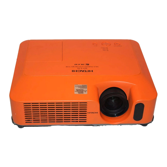
Multimedia LCD Projector
All manuals and user guides at all-guides.com
Caution
Service Warning
Contents
April 2006
No.0567E
YK
ED-X10/ED-X12
(CC9XM2)
8. Disassembly diagram ----------------------------------- 40
9. Replacement parts list ---------------------------------- 47
10.RS-232C communication ------------------------------- 49
11. Block diagram --------------------------------------------- 59
12. Connector connection diagram ----------------------- 60
13.Basic circuit diagram ------------------------------------ 61
Advertisement
Table of Contents

Related Manuals for Hitachi ED-X10


Summary of Contents for Hitachi ED-X10
-
Page 1: Table Of Contents
Be sure to read this manual before servicing. To assure safety from fi re, electric shock, injury, harmful radiation and materials, various measures are provided in this Hitachi Multimedia LCD Projector. Be sure to read cautionary items described in the manual to maintain safety before servicing. -
Page 2: Features
All manuals and user guides at all-guides.com ED-X10/ED-X12(CC9XM2) 1. Features • High Brightness • Low Noise • Rich Connectivity • Compact Body 2. Specifications Drive system TFT active matrix Liquid crystal Panel size 1.6cm(0.63 type) panel Number of pixels 1024 (H) x 768 (V) -
Page 3: Names Of Each Part
All manuals and user guides at all-guides.com ED-X10/ED-X12(CC9XM2) 3. Names of each part ● Projector Control buttons Lamp cover Remote sensor (Lamp unit is inside.) Speaker Zoom ring Security bar Focus ring (Use for attaching a commercial anti-theft chain or wire.) - Page 4 All manuals and user guides at all-guides.com ED-X10/ED-X12(CC9XM2) Power switch AC inlet Elevator button Ports (See below.) Elevator foot Rear-Left side Vent AUDIO IN1 port (In the default setting, the AUDIO IN1 port is the audio port for the RGB IN1 port, however, it is possible to AUDIO IN3 L/R port change the settings.)
- Page 5 All manuals and user guides at all-guides.com ED-X10/ED-X12(CC9XM2) Control buttons LAMP indicator TEMP indicator Cursor buttons POWER indicator ▲,▼,◄,► STANDBY/ON button INPUT button Remote control SEARCH button STANDBY/ON button RGB button AUTO button SEARCH VIDEO VIDEO button BLANK button BLANK...
-
Page 6: Adjustment
All manuals and user guides at all-guides.com ED-X10/ED-X12(CC9XM2) 4. Adjustment 4-1 Before adjusting 4-1-1 Selection of adjustment When any parts in the table 4-1 are changed, choose the proper adjusting items with the chart. Table 4-1: Relation between the replaced part and adjustment... - Page 7 All manuals and user guides at all-guides.com ED-X10/ED-X12(CC9XM2) 4-2 Flicker adjustment (V.COM adjustment) Adjustment procedure Test pattern for the adjustment 1. Use DAC-P - V.COM - R: in the FACTORY MENU to adjust so that the flicker at the center of the screen is less than the flicker at the periphery.
- Page 8 All manuals and user guides at all-guides.com ED-X10/ED-X12(CC9XM2) 4-5 E-POS adjustment (vertical bars adjustment 2) Test pattern for the adjustment Adjustment procedure 1. Make this adjustment after completing the ad- justment in the section 4-4. 2. Open FACTORY MENU. Select DAC-P > E-POS >...
- Page 9 All manuals and user guides at all-guides.com ED-X10/ED-X12(CC9XM2) 4-7 Color uniformity adjustments Preparations 1. Perform these adjustments after the adjustments 5. Adjustment point No.1 should not be adjusted, described in the section 4-6. because it controls the brightness of the entire 2.
- Page 10 All manuals and user guides at all-guides.com ED-X10/ED-X12(CC9XM2) Adjustment procedure 1 (When a color differential meter is used) Note: Since excessive correction may lead to a 1. First adjust the [MID-1] tone [G:]. correction data overview during internal 2. Select adjustment point [No.2][G:].
- Page 11 All manuals and user guides at all-guides.com ED-X10/ED-X12(CC9XM2) Adjustment procedure 2 (visual inspection) same color as measurement point [No.1]. 1. First adjust [MIN] tone [G:]. Adjustment technique: 2. Select [No.2] [G:]. First, adjust [B:] of the point whose color is to...
-
Page 12: Troubleshooting
All manuals and user guides at all-guides.com ED-X10/ED-X12(CC9XM2) 5. Troubleshooting Check points THERMAL SWITCH (TSW) E801 S801 IS01 E800 IS06 IS07 E301 IS08 IS09 E802 P501 IS03 IS02 P601 D303 D301 (LAMP) (POWER) D302 E304 (TEMP) P701 E807 PWB assembly MAIN... - Page 13 All manuals and user guides at all-guides.com ED-X10/ED-X12(CC9XM2) Power can not be turned on *: Be sure to unplug the power cord before measuring resistance. voltage Measure supplied at pins (6) resistance* between pins 0Ω and (8) of E800 on the PWB...
- Page 14 All manuals and user guides at all-guides.com ED-X10/ED-X12(CC9XM2) Lamp does not light *: Be sure to unplug the power cord before measuring resistance. What is the state of Blinks Light LAMP indicator D303 during operation? Is the Measure LAMP installation...
- Page 15 All manuals and user guides at all-guides.com ED-X10/ED-X12(CC9XM2) Picture is not displayed. Confirm the splash screen the LCD Panels CPC30 connector A/B and the user menu displayed connection to the MAIN correctly? board. PWB assembly MAIN LCD/Lens prism assembly Are all...
- Page 16 All manuals and user guides at all-guides.com ED-X10/ED-X12(CC9XM2) No sound Check at operating mode (Make sure the state of MUTE and Volume) Disconnect the speaker from the infinity PWB assembly Main, and Speaker measure its resistance. about 8 PWB assembly Main...
-
Page 17: Service Points
All manuals and user guides at all-guides.com ED-X10/ED-X12(CC9XM2) 6. Service points 6-1 Lead free solder [CAUTION] This product uses lead free solder (unleaded) to help preserve the environment. Please read these instructions before attempting any soldering work. CAUTION Always wear safety glasses to prevent fumes or molten solder from getting into the eyes. Lead free solder can splatter at high temperatures (600˚C). - Page 18 Therefore, regarding these parts, you can either replace part, LCD/Lens prism assembly, or send the whole unit LCD/Lens prism assembly back to HITACHI, where we will replace the malfunctioning part, recondition the device and send it back to you.
- Page 19 All manuals and user guides at all-guides.com ED-X10/ED-X12(CC9XM2) 3. Maintenance point Swab Panel Each color part has same construction. By using swab and air duster, Holder you can easily remove dust from panel and optical filter. Optical filter Actual formation Separatied formation 4.
- Page 20 All manuals and user guides at all-guides.com ED-X10/ED-X12(CC9XM2) 6-4 Putting batteries WARNING Always handle the batteries with care and use them only as directed. Improper use may result in battery explosion, cracking or leakage, which could result in fire, injury and/or pollution of the surrounding environ- ment.
- Page 21 All manuals and user guides at all-guides.com ED-X10/ED-X12(CC9XM2) 6-5 Air filter WARNING • Before caring, make sure the power switch is off and the power cable is not plugged in, then allow the projector to cool suffi ciently. The care in a high temperature state of the projector could cause an electric shock, a burn and/or malfunction to the projector.
- Page 22 All manuals and user guides at all-guides.com ED-X10/ED-X12(CC9XM2) 6-6 Lamp WARNING HIGH VOLTAGE HIGH TEMPERATURE HIGH PRESSURE ● The projector uses a high-pressure mercury glass lamp. The lamp can break with a loud bang, or burn out, if jolted or scratched, handled while hot, or worn over time. Note that each lamp has a different life- time, and some may burst or burn out soon after you start using them.
- Page 23 All manuals and user guides at all-guides.com ED-X10/ED-X12(CC9XM2) Replacing the Lamp A lamp has a fi nite product life. Using the lamp for long periods of time could cause the pictures darker or the color tone poor. Note that each lamp has a different lifetime, and some may burst or burn out soon after being started using.
- Page 24 All manuals and user guides at all-guides.com ED-X10/ED-X12(CC9XM2) 6-7 Other care WARNING Before caring, make sure the power switch is off and the power cable is not plugged in, and then allow the projector to cool suffi ciently. The care in a high temperature state of the projector could cause a burn and/ or malfunction to the projector.
- Page 25 All manuals and user guides at all-guides.com ED-X10/ED-X12(CC9XM2) 6-8 Notice of AUTO adjustment Use of AUTO adjustment with the image through RGB input optimizes V_POSI, H_POSI, H_SIZE and H_PHASE automatically. In case that projected image has dark tone around its peripheral, AUTO operation sometimes makes artifacts in the image, shifts capture area and so on.
- Page 26 All manuals and user guides at all-guides.com ED-X10/ED-X12(CC9XM2) 6-9 How to inactivate the security functions This projector is equipped with security functions. (1)MyScreen PASSWORD The MyScreen PASSWORD function can be used to prohibit access to the MyScreen function and pre- vent the currently registered MyScreen image from being overwritten.
- Page 27 PIN BOX (ID Inquiring Code) 2. Send HITACHI sales company the Inquiring code (10 digits) to inquire the correct PIN code. 3. With the PIN BOX menu displayed, input the correct PIN code. Enter the correct PIN CODE that HITACHI sales company informed.
- Page 28 All manuals and user guides at all-guides.com ED-X10/ED-X12(CC9XM2) 6-11 Related Messages When the unit’s power is on, messages such as those shown below may be displayed. When any such message is displayed on the screen, please respond as described below.
- Page 29 All manuals and user guides at all-guides.com ED-X10/ED-X12(CC9XM2) 6-12 Regarding the indicator lamps Lighting and flashing of the POWER indicator, the LAMP indicator, and the TEMP indicator have the mean- ings as described in the table below. Please respond in accordance with the instructions within the table.
- Page 30 All manuals and user guides at all-guides.com ED-X10/ED-X12(CC9XM2) 6-13 HIDDEN SERVICE MENU To display the OSD for “HIDDEN SERVICE MENU” set up. HIDDEN SERVICE By the control panel By the remote control transmitter AIR-SENSOR EXECUTE 1. Display the Advanced menu by 1.
-
Page 31: Wiring Diagram
All manuals and user guides at all-guides.com ED-X10/ED-X12(CC9XM2) 7. Wiring diagram... - Page 32 All manuals and user guides at all-guides.com ED-X10/ED-X12(CC9XM2)
- Page 33 All manuals and user guides at all-guides.com ED-X10/ED-X12(CC9XM2)
- Page 34 All manuals and user guides at all-guides.com ED-X10/ED-X12(CC9XM2)
- Page 35 All manuals and user guides at all-guides.com ED-X10/ED-X12(CC9XM2)
- Page 36 All manuals and user guides at all-guides.com ED-X10/ED-X12(CC9XM2)
- Page 37 All manuals and user guides at all-guides.com ED-X10/ED-X12(CC9XM2)
- Page 38 All manuals and user guides at all-guides.com ED-X10/ED-X12(CC9XM2)
- Page 39 All manuals and user guides at all-guides.com ED-X10/ED-X12(CC9XM2)
-
Page 40: Disassembly Diagram
All manuals and user guides at all-guides.com ED-X10/ED-X12(CC9XM2) 8. Disassembly diagram... - Page 41 All manuals and user guides at all-guides.com ED-X10/ED-X12(CC9XM2)
- Page 42 All manuals and user guides at all-guides.com ED-X10/ED-X12(CC9XM2) Notice 1. Detach and attach the upper case. Follw the procedure below to detach and attach the upper case. When disassembling a. Remove the Lamp door. CAUTION The lamp door must be removed before the upper case when disassembling the machine. If the upper case is detached with the lamp door installed, the MAIN board might be damaged.
- Page 43 All manuals and user guides at all-guides.com ED-X10/ED-X12(CC9XM2) When assembling a. Before attaching the upper case. Make sure that the speaker wires are routed correctly. NOTICE : Speaker cone Make sure that the soldering point of the wires and the speaker is within the shaded area as indicated in the drawing.
- Page 44 All manuals and user guides at all-guides.com ED-X10/ED-X12(CC9XM2) c. Attach the Lamp door. Lamp door CAUTION Tighten this screw using a manual screwdriver. 2. Replacing the power units. Remove the 4 screws to take off the ballast bracket. NOTE : One of screws is behind the Front Shade.
- Page 45 All manuals and user guides at all-guides.com ED-X10/ED-X12(CC9XM2) 3. Detaching and attaching the Panel Fan Duct assembly When disassembling Remove 4 screws and unhook the panel fan duct assembly as shown in the diagram. Panel fan duct assembly Lamp fan Push each of hooks in the direction of the arrows, while lifting the panel fan duct assembly, when removing it.
- Page 46 All manuals and user guides at all-guides.com ED-X10/ED-X12(CC9XM2) 4. Attaching the dichroic optics unit Put the dichroic optics unit on the bottom case, and tighten screws in order of 1, 2, 3 and 4 as shown in the diagram. Some of dichroic optics units have an extra hole shown in the diagram.
-
Page 47: Replacement Parts List
All manuals and user guides at all-guides.com ED-X10/ED-X12(CC9XM2) 9. Replacement Parts list PRODUCT SAFETY NOTE : Components marked with a have special characteristics important to safety. Before replacing any of there components, read carefully, the PRODUCT SAFETY NOTICE of this Service Manual. Don't degrade the safety of the projector through improper servicing. - Page 48 All manuals and user guides at all-guides.com ED-X10/ED-X12(CC9XM2) ED-X12 SYMBOL PARTS SYMBOL PARTS DESCRIPTION DESCRIPTION QD52677 CC9-2 UPPER CASE ASS’Y UX24923 CC9-2D LCD/LENS PRISM ASS’Y(SERVICE or REPAIR) PC06572 CONT BUTTON ASSY DT00757 CC9-2D LAMP UNIT ASS’Y QD50832 LAMP DOOR ASS’Y...
-
Page 49: Rs-232C Communication
All manuals and user guides at all-guides.com ED-X10/ED-X12(CC9XM2) 10. RS-232C communication RS-232C cable(Cross) CONTROL port RS-232C port of the projector of a computer - (1) (1) CD RD (2) (2) RD TD (3) (3) TD - (4) (4) DTR GND (5) - Page 50 All manuals and user guides at all-guides.com ED-X10/ED-X12(CC9XM2) Requesting projector status (Get command) (1) Send the request code Header + Command data (‘02H’+‘00H’+ type (2 bytes)+ ‘00H’+‘00H’) from the computer to the projector. (2) The projector returns the response code ‘1DH’+ data (2 bytes) to the computer.
- Page 51 All manuals and user guides at all-guides.com ED-X10/ED-X12(CC9XM2) Command data chart Command Data Names Operation Type Header Action Type Setting Code Power Turn off BE EF 06 00 2A D3 01 00 00 60 00 00 Turn on BE EF...
- Page 52 All manuals and user guides at all-guides.com ED-X10/ED-X12(CC9XM2) Command Data Names Operation Type Header Action Type Setting Code User Gamma Pattern BE EF 06 00 FB FA 01 00 80 30 00 00 9 step gray scale BE EF 06 00...
- Page 53 All manuals and user guides at all-guides.com ED-X10/ED-X12(CC9XM2) Command Data Names Operation Type Header Action Type Setting Code COLOR TEMP GAIN G BE EF 06 00 70 F4 02 00 B2 30 00 00 Increment BE EF 06 00 16 F4...
- Page 54 All manuals and user guides at all-guides.com ED-X10/ED-X12(CC9XM2) Command Data Names Operation Type Header Action Type Setting Code ASPECT BE EF 06 00 9E D0 01 00 08 20 00 00 16:9 BE EF 06 00 0E D1 01 00...
- Page 55 All manuals and user guides at all-guides.com ED-X10/ED-X12(CC9XM2) Command Data Names Operation Type Header Action Type Setting Code FRAME LOCK TURN OFF BE EF 06 00 CB D6 01 00 14 30 00 00 TURN ON BE EF 06 00...
- Page 56 All manuals and user guides at all-guides.com ED-X10/ED-X12(CC9XM2) Command Data Names Operation Type Header Action Type Setting Code MUTE TURN OFF BE EF 06 00 46 D3 01 00 02 20 00 00 TURN ON BE EF 06 00 D6 D2...
- Page 57 All manuals and user guides at all-guides.com ED-X10/ED-X12(CC9XM2) Command Data Names Operation Type Header Action Type Setting Code BLANK My Screen BE EF 06 00 FB CA 01 00 00 30 20 00 ORIGINAL BE EF 06 00 FB E2...
- Page 58 All manuals and user guides at all-guides.com ED-X10/ED-X12(CC9XM2) Command Data Names Operation Type Header Action Type Setting Code REMOTE FREQ Disable BE EF 06 00 FF 3D 01 00 30 26 00 00 NORMAL Enable BE EF 06 00 6F 3C...
-
Page 59: Block Diagram
All manuals and user guides at all-guides.com ED-X10/ED-X12(CC9XM2) 11. Block diagram... -
Page 60: Connector Connection Diagram
All manuals and user guides at all-guides.com ED-X10/ED-X12(CC9XM2) 12. Connector connection diagram COMPONENT VIDEO-IN EV02 EASP SPEAKER PWB assembly MAIN OUT- OUT+ Cb/Pb Cr/Pr assembly REMC VDDY (EXHAUST) VSSX (R,G PANEL) ENBX4 /CLX VDDX (LAMP) VID5 VID7 (B PANEL) CONTROL ET01... -
Page 61: Basic Circuit Diagram
All manuals and user guides at all-guides.com ED-X10/ED-X12(CC9XM2) 13. Basic circuit diagram Parts with hatching are not mounted. CONFIDENTIAL PWB assembly CONTROL (CC9XM2) PWB assembly REMOTE (CC9XM2) - Page 62 All manuals and user guides at all-guides.com ED-X10/ED-X12(CC9XM2) MEMO...
- Page 63 All manuals and user guides at all-guides.com CONFIDENTIAL Warning POWER UNIT (BALLAST) 1 (CC9XM2) For handling of the circuit diagram, refer to the warning on the cover.
- Page 64 All manuals and user guides at all-guides.com CONFIDENTIAL Warning POWER UNIT (BALLAST) 2 (CC9XM2) For handling of the circuit diagram, refer to the warning on the cover.
- Page 65 All manuals and user guides at all-guides.com CONFIDENTIAL Warning POWER UNIT (CIRCUIT) (CC9XM2) For handling of the circuit diagram, refer to the warning on the cover.
- Page 66 All manuals and user guides at all-guides.com CONFIDENTIAL +3.3VPW I201 I201 I201 PW190 PERIPHERALS PW190 DIGITAL INPUT PORT DISPLAY PORT PW190 R2C4 CH0CK IN0CLK IN0CLP CH0CP NC-D13 R2C5 DCLKOUT DCLK CH0PE IN0PEN IN0CST CH0CS NC-E18 1005 R2C6 CH0VB IN0VBI NC-D14 1005 CH0AH IN0AHS...
- Page 67 All manuals and user guides at all-guides.com CONFIDENTIAL TEA1 R226 TEA2 L251 TEA3 I201 2010 R227 1608 RESETN TEA4 PW190 R200 2.5V TEA5 65mA 1005 1005 R203 AC15 AC15 1.0K R217 AE16 AE16 1005 Q201 AF16 AF16 +4.1V C273 DTC114EUA 2010 R204 AC16...
- Page 68 All manuals and user guides at all-guides.com CONFIDENTIAL R316 For "N" "WL" model E3W1 1005 R317 L321 ZH-12V R3A3 AP321 1005 L322 LED POW-G +6.6V 1608 L371 1005 AP322 L323 LED POW-R +3.3V 1608 AP323 2518 I310 L324 LED TEMP SN74LVC1G126DCK 1608 C371...
- Page 69 All manuals and user guides at all-guides.com CONFIDENTIAL R836 R835 1005 1005 MOUSE Q809 2SC5343UFG PWRC I801 I802 I803 I808 SI-3010KM BA00BC0WFP BA00BC0WFP BD00KA5WFP-E2 RC_EN38 15.5V-Panel 3.3V-Panel RC_EN56 1.2V-TG I892 ROHM Reg 3.3V-CPU L816 C823 SN74LVC1G97DCK 0.033/16 1.8V-CPU SLF6028 +1.8VCPU 1005 I807 TPS40222DR...
- Page 70 All manuals and user guides at all-guides.com CONFIDENTIAL I401 L401 L3E07110K0A L3E07110K0A 1/4 2518 +3.3VP +1.2V VDD1-D7 L402 VDD1-D8 C421 VDD1-D9 2.2/6.3 2518 VDD1-D10 HRESET0 CHHRST C422 VDD1-D11 VRESET0 CHVRST 0.01/16 VDD1-D12 HPLL CHHPLL 1005 VDD1-D13 CLP1 CHCP1 C423 VDD1-E7 CLP2 CHCP2 R442...
- Page 71 All manuals and user guides at all-guides.com CONFIDENTIAL CC9XM2 R Panel Part +3.3VP +15.5V SHCLKR SHCLKR DIRXR DIRXR ENBXR1 ENBXR1 0 ohm R 0 ohm R ENBXR5 ENBXR5 DXOUTR DXOUTR CLXOUTR P501 CLXOUTR DYOUTR 54104-36HUp APR36 DYOUTR CLYOUTR RLCCOM CLYOUTR LCCOM ENBYR1 APR35...
- Page 72 All manuals and user guides at all-guides.com CONFIDENTIAL CC9XM2 G Panel Part +3.3VP +15.5V SHCLKG SHCLKG DIRXG DIRXG ENBXG1 ENBXG1 ENBXG5 ENBXG5 DXOUTG DXOUTG CLXOUTG P601 CLXOUTG DYOUTG 54104-36HUp APG36 DYOUTG CLYOUTG GLCCOM CLYOUTG LCCOM ENBYG1 APG35 ENBYG1 ENBYG2 ENBYG2 VDDY APG34 XFRG...
- Page 73 All manuals and user guides at all-guides.com CONFIDENTIAL CC9XM2 B Panel Part +3.3VP +15.5V SHCLKB SHCLKB DIRXB DIRXB ENBXB1 ENBXB1 ENBXB5 ENBXB5 DXOUTB DXOUTB CLXOUTB P701 CLXOUTB 54104-36HUp DYOUTB APB36 DYOUTB CLYOUTB BLCCOM CLYOUTB LCCOM ENBYB1 APB35 ENBYB1 ENBYB2 ENBYB2 VDDY APB34 XFRB...
- Page 74 All manuals and user guides at all-guides.com CONFIDENTIAL GND1 RV48 RV49 DSUB1_B RV50 2 1005 DSUB1_G 1005 DSUB1_R +3.3V RGB.H 1005 RGB.V ES04 ZH-11V GND1 GND1 APW01 RV80 Analog Red (Wireless) HV09 APW02 SC200JT 1005 GND1 RV77 2125 APW04 RV82 Analog Green (Wireless) GND1 HV10...
- Page 75 All manuals and user guides at all-guides.com CONFIDENTIAL RS05 RS06 1005 RS04 1005 1005 LS01 APDG 2518 QS02 SRC1202EF ES01 3114-15FA CS03 GND1 10/6.3 CS09 APCL 2125 IS02 EL8302IUZ-T7 RS34 1.0p-C 560-1% HS10 INA+ INA- 1005 SC200JT SYNC 1005 RS37 2125 75-1% OUTA...
- Page 76 All manuals and user guides at all-guides.com CONFIDENTIAL Sheet 9 R_WL_in Wireless LAN Audio Sheet 9 L_WL_in Audio in Monitor IA03 BA00BC0WFP TPR-in TPL-in RA71 1005 IA01 GND1 BD3883FS CA65 4.7/16 RA42 Sheet 9 R1_IN VIN1 REC1 2125 Audio IN3 CA66 4.7/16 1005...
- Page 77 All manuals and user guides at all-guides.com CONFIDENTIAL IK21 RRX6000-0702L CK22 VSS1 /RST 1.0/10 XK25 6MHz OSC1 PTA0 OSC2 PTA1 RK30 VREG PTA2 1005 PTA3 PTD0 PTE0/TCLK PTD1 PTE2/TCH1 PTD2 PTA4 PT03 PTA5 PTD4 PTA6 RK27 PTE1/TCH0 PTA7 1005 PTE3/D+ PTD5 PTE4/D- PTD6...
- Page 78 All manuals and user guides at all-guides.com RE38 CONFIDENTIAL 2010 RE39 1005 RE40 *CE19 1005 0.01/16 1 1005 *IE02 *RE41 SN74LVC541APW 1005 TEA1 *RE44 TEA2 2010 TEA3 TEA4 TEA5 *RE45 *RE48 PCS0 *RE46 1005 1005 *RE43 1005 1005 RE47 1005 CHKE13 *LE10 C1V222-2A...
- Page 79 All manuals and user guides at all-guides.com ED-X10/ED-X12(CC9XM2) Basic circuit diagram list PWB assembly CONTROL PWB assembly MAIN 5 PWB assembly REMOTE PWB assembly MAIN 6 POWER UNIT BALLAST 1 PWB assembly MAIN 7 POWER UNIT BALLAST 2 PWB assembly MAIN 8...
- Page 80 All manuals and user guides at all-guides.com ED-X10/ED-X12 YK No.0567 QR68301 Printed in Japan (JE)