Advertisement
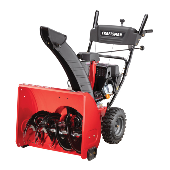
SNOW BLOWER
Model Nos.
CMGSB24208
CMGSB26208
CMXGBAM1054541
CMXGBAM1054542
CMXGBAM1054543
CMXGBAM1413943
CMXGBAM1413942
CMXGBAM1054544
CMXGBAM1054546
IF YOU HAVE QUESTIONS OR COMMENTS, CONTACT US.
SI TIENE DUDAS O COMENTARIOS, CONTÁCTENOS.
1-888-331-4569
Before using this equipment, read the manual and follow all safety rules and operating instructions. SAVE THESE INSTRUCTIONS.
Antes de usar este producto, lea este manual y siga todas las reglas de seguridad e instrucciones de funcionamiento.
GUARDE ESTAS INSTRUCCIONES!
NOTE: This Operator's Manual covers several models. Features may vary by model. Not all features in this manual are applicable to all models and the model depicted may differ
from yours. The terms "snow thrower" and "snow blower" may be used interchangeably for this product.
NOTA: Este Manual del Operador, corresponde a numerosos modelos. No todas las características técnicas que se incluyen en este manual se aplican a todos los modelos y la
máquina que se ilustra aquí puede diferir de la suya.
INSTRUCTION MANUAL | MANUAL DE INSTRUCTIONES
WARNING!
ADVERTENCIA
WWW.CRAFTSMAN.COM
Form No. 769-22276
(May 20, 2019)
Advertisement

Related Manuals for Craftsman CMGSB24208


Summary of Contents for Craftsman CMGSB24208
- Page 1 INSTRUCTION MANUAL | MANUAL DE INSTRUCTIONES SNOW BLOWER Model Nos. CMGSB24208 CMGSB26208 CMXGBAM1054541 CMXGBAM1054542 CMXGBAM1054543 CMXGBAM1413943 CMXGBAM1413942 CMXGBAM1054544 CMXGBAM1054546 IF YOU HAVE QUESTIONS OR COMMENTS, CONTACT US. SI TIENE DUDAS O COMENTARIOS, CONTÁCTENOS. 1-888-331-4569 WWW.CRAFTSMAN.COM WARNING! Before using this equipment, read the manual and follow all safety rules and operating instructions. SAVE THESE INSTRUCTIONS.
-
Page 2: Table Of Contents
TABLE OF CONTENTS Safe Operation Practices ......Page 3 Off-Season Storage ......Page 34 Assembly . -
Page 3: Safe Operation Practices
SAFETY INSTRUCTIONS WARNING DANGER This symbol points out important safety instructions which, if not This machine was built to be operated according to the safe operation followed, could endanger the personal safety and/or property of practices in this manual. As with any type of power equipment, yourself and others. - Page 4 SAFETY INSTRUCTIONS • If gasoline is spilled, wipe it off the engine and equipment. Move unit to • Disengage all control levers and stop engine before you leave the operating another area. Wait 5 minutes before starting the engine. If fuel is spilled on position (behind the handles).
- Page 5 SAFETY INSTRUCTIONS • Observe proper disposal laws and regulations for gas, oil, etc. to protect the environment. • Prior to storing, run machine a few minutes to clear snow from machine and prevent freeze up of auger/impeller. • Never store the machine or fuel container inside where there is an open flame, spark or pilot light such as a water heater, furnace, clothes dryer etc.
- Page 6 SAFETY INSTRUCTIONS SAFETY SYMBOLS This page depicts and describes safety symbols that may appear on this product. Read, understand, and follow all instructions on the machine before attempting to assemble and operate. Symbol Description READ THE OPERATOR’S MANUAL(S) Read, understand, and follow all instructions in the manual(s) before attempting to assemble and operate.
-
Page 7: Assembly
ASSEMBLY NOTE: This Operator’s Manual covers several models. Features may vary by model. Not all features in this manual are applicable to all models and the model depicted may differ from yours. Refer to Figure 1 which shows the different versions and match the contents of carton (chute and directional control rod) to identify your specific unit. Chute Standard Side Crank Rod Overhead Chute... - Page 8 ASSEMBLY NOTE: References to right or left side of the snow blower are determined from Loosen the top two lock nuts securing the upper and lower handle and behind the unit in the operating position (standing directly behind the snow remove the two carriage screws from the lower handle and set aside.
- Page 9 ASSEMBLY Place shift lever in Forward-6 position or fastest forward speed (if equipped). Pull up and back on upper handle as shown in Figure 5. As you are raising the handle upward, make sure that both ends of the center cable are positioned properly in the brackets.
- Page 10 ASSEMBLY Standard Side Crank Chute Control Close flange keepers to secure chute assembly to chute base. Flange keepers will click into place when properly secure. See Figure 10. Figure 10 NOTE: Ensure the lower chute is secured to the flange on the chute base. The lower edge of the chute keeper should be positioned below the flange on the chute base after being clicked into place.
- Page 11 ASSEMBLY Overhead Chute Control (w/ Chute Control Rod) Place chute assembly onto chute base and secure chute control head to chute support bracket with clevis pin and cotter pin removed in Step 1. See Figure Figure 14 Finish securing chute control head to chute support bracket with wing nut (a) and hex screw (b) removed in Step 1.
- Page 12 ASSEMBLY 2-Way & 4-Way Chute Control Insert chute control rod into the support bracket on rear of the dash panel. See Figure 16. Figure 16 Remove hairpin clip (a) from rear of chute control head. See Figure 17. Figure 18 Remove hairpin clip, wing nut and hex screw from chute control head and clevis pin and bow-tie cotter pin from chute support bracket.
- Page 13 ASSEMBLY Squeeze trigger on joystick and rotate chute by hand to face forward. The NOTE: For smoothest operation, cables should all be to the left of the chute holes in chute control input will be facing up. See Figure 22. directional control rod.
- Page 14 ASSEMBLY Electric Chute Control Figure 24 NOTE: Chute control rod will fit snug into pinion gear. Support rear of dash panel with one hand while inserting rod with your other hand to ensure rod is inserted into pinion gear. all the way NOTE: The hole in the chute directional control rod is a reference for aligning rod with indicator arrow on pinion gear, and will be visible after rod has been inserted.
- Page 15 ASSEMBLY Insert the round end of the chute control rod into input of chute control Finish securing chute control head by installing hex screw and wing nut head. Push rod as far into the chute control head as possible, keeping the removed in Step 2.
- Page 16 ASSEMBLY Set-Up Push the chute control rod toward the control panel until the hole in the rod lines up with the middle hole in the chute control input and insert the cotter Chute Control Cable Routing (If Equipped) pin removed in Step 1. See Figure 32. For units equipped with 2-way or 4-way chute control joystick, electric chute control and/or chute-pitch controls, ensure control cables are routed properly.
- Page 17 ASSEMBLY Chute Clean-Out Tool Adjustments A chute clean-out tool is fastened to the top of the auger housing with a mounting Skid Shoes clip. See Figure 35. The tool is designed to clear a chute assembly of ice and The snow blower skid shoes are adjusted at the factory to be approx 1/8” below snow.
- Page 18 ASSEMBLY Auger Control WARNING Prior to operating your snow blower, carefully read and follow all instructions below. Perform all adjustments to verify your snow blower is operating safely and properly. Check the adjustment of the auger control as follows: The auger control is located on the left handle. See Figure 37 inset. When the auger control is released and in the disengaged “UP”...
-
Page 19: Operation
Recoil Starter Handle Choke Electric Starter Oil Drain Control Button Electric Starter Oil Fill Outlet/Switchbox Electric Starter Outlet Oil Drain Figure 38 Meets ANSI Safety Standards Craftsman Snow Blowers conform to the safety standard of the American National Standards Institute (ANSI). - Page 20 OPERATION Throttle Control Now that you have set up your snow blower, it’s important to become acquainted with its controls and features. Refer to Figure 38. NOTE: This Operator’s Manual covers several models. Snow blower features may vary by model. Not all features in this manual are applicable to all snow blower models and the snow blower depicted may differ from yours.
- Page 21 OPERATION Overhead Chute Directional Control (If Equipped) Auger Control AUGER CHUTE DIRECTIONAL CONTROL CONTROL ADJUSTABLE CHUTE TILT DISCHARGE DISCHARGE LEFT RIGHT The overhead chute directional control is located in the center of the snow blower The auger control is located on the left handle. Squeeze the control grip against the between the handle panel and lower handle.
- Page 22 OPERATION Four-Way Chute Control (Joystick) (If Equipped) Clean-Out Tool WARNING Never use your hands to clear a clogged chute assembly. Shut off engine and remain behind handles until all moving parts have stopped before using the clean-out tool to clear the chute assembly. The chute clean-out tool is conveniently fastened to the rear of the auger housing with a mounting clip.
- Page 23 OPERATION Before Starting Engine Gasoline Use automotive gasoline (unleaded or low leaded to minimize combustion chamber WARNING deposits) with a minimum of 87 octane. Gasoline with up to 10% ethanol or 15% MTBE (Methyl Tertiary Butyl Ether) can be used. Never use an oil/gasoline mixture Read, understand, and follow all instructions and warnings on the or dirty gasoline.
- Page 24 OPERATION Electric Starter Pull gently on the starter handle until it begins to resist, then pull quickly and forcefully to overcome the compression. Do not release the handle and WARNING allow it to snap back. Return rope SLOWLY to original position. If required, repeat this step.
- Page 25 OPERATION Replacing Shear Pins WARNING NEVER replace the auger shear pins with anything other than OEM Part No. 738-04124A (round head replacement shear pins), 738-05273 (black colored, round head replacement shear pins) or 738-06654 (hex head replacement shear pins). Any damage to the auger gearbox or other components as a result of failing to do so will NOT be covered by your snow thrower’s warranty.
-
Page 26: Service &Maintenance
SERVICE AND MAINTENANCE MAINTENANCE SCHEDULE Follow the maintenance schedule given below. This chart describes service WARNING guidelines only. Use the Service Log column to keep track of completed Before performing any type of maintenance/service, disengage all controls maintenance tasks. To locate the nearest Service Center or to schedule service, call and stop the engine. - Page 27 SERVICE AND MAINTENANCE NOTE: Check the spark plug once a season or every 25 hours of operation. Change CAUTION the spark plug once a season or every 100 hours. To ensure proper engine operation, Used oil is a hazardous waste product. Dispose of used oil properly. Do not the spark plug must be properly gapped and free of deposits.
- Page 28 SERVICE AND MAINTENANCE Wheels Electrode At least once a season, remove both wheels. Clean and coat the axles with a multipurpose automotive grease before reinstalling wheels. Chute Directional Control Once a season, lubricate the eye bolt bushing and spiral with 3-in-1 oil. Auger Shaft At least once a season, remove the shear pins on auger shaft.
- Page 29 SERVICE AND MAINTENANCE Reassemble new shave plate, making sure heads of carriage bolts are to the To ensure proper shift cable tension perform the following: inside of housing. Tighten securely. See Figure 47. Start the engine and place the shift lever in the slowest forward speed. Using the drive control, ensure the unit moves forward.
- Page 30 SERVICE AND MAINTENANCE Drive Control Chute Control Rod To achieve more chute control rod engagement in the input shaft under the handle When the drive control is released and in the disengaged “up” position, the cable should have very little slack. It should NOT be tight. Also, if there is excessive slack panel, the chute control rod will have to be adjusted.
- Page 31 SERVICE AND MAINTENANCE Auger Control Figure 54 Roll the auger belt off the engine pulley. See Figure 55. Refer to the Assembly section for instructions on adjusting the auger control cable. Skid Shoes Refer to the Assembly section for instructions on adjusting the skid shoes. Belt Replacement Auger Belt To remove and replace your snow blower’s auger belt, proceed as follows:...
- Page 32 SERVICE AND MAINTENANCE Loosen and remove the shoulder screw which acts as a belt keeper. Refer to Drive Belt Figure 57. NOTE: Several components must be removed and special tools are required in order to replace the snow blower’s drive belt. Contact the nearest Parts & Repair Center to have the drive belt replaced.
- Page 33 SERVICE AND MAINTENANCE Carefully remove the hex nut and washer which secures the hex shaft to Follow the steps above in reverse order to reassemble components. the snow blower frame and lightly tap the shaft’s end to dislodge the ball Perform the test previously described in the Drive Control section.
-
Page 34: Off-Season Storage
OFF-SEASON STORAGE If the snow blower will not be used for 30 days or longer, or if the end of the snow season, the equipment needs to be stored properly. Follow storage instructions below to ensure top performance from the snow blower for future use. Preparing Engine Preparing Snow Blower Engines stored over 30 days need to be drained of fuel to prevent deterioration and... -
Page 35: Troubleshooting
TROUBLESHOOTING WARNING Disconnect the spark plug wire and ground it against the engine to prevent unintended starting. Before performing any type of maintenance/service, disengage all controls and stop the engine. Wait until all moving parts have come to a complete stop. Always wear safety glasses during operation or while performing any adjustments or repairs. - Page 36 TROUBLESHOOTING Problem Cause Remedy Unit fails to discharge snow 1. Chute assembly clogged. 1. Stop engine immediately and disconnect spark plug wire. Clean chute assembly and inside of auger housing with clean-out tool. 2. Foreign object lodged in auger. 2. Stop engine immediately and disconnect spark plug wire. Remove object from auger with clean-out tool.
-
Page 37: Español
Product Manufactured by (Producto fabricado por): MTD LLC, P.O. BOX 361131 CLEVELAND, OHIO 44136-0019 CRAFTSMAN® is a registered trademark of Stanley Black & Decker, Inc., used under license. CRAFTSMAN® es una marca registrada de Stanley Black & Decker, Inc., utilizada bajo licencia.