Sony WRR-801A Service Manual
Hide thumbs
Also See for WRR-801A:
- Operating instructions manual (44 pages) ,
- Operating instructions manual (16 pages) ,
- Operating instructions manual (52 pages)

Related Manuals for Sony WRR-801A


Summary of Contents for Sony WRR-801A
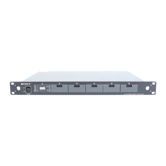
- Page 1 UHF SYNTHESIZED DIVERSITY TUNER WRR-801A UHF SYNTHESIZED TUNER UNIT WRU-801A SERVICE MANUAL U Model...
- Page 2 ! WARNING SAFETY CHECK-OUT This manual is intended for qualified service personnel After correcting the original service problem, only. perform the following safety checks before To reduce the risk of electric shock, fire or injury, do not releasing the set to the customer : perform any servicing other than that contained in the operating instructions unless you are qualified to do so.
-
Page 3: Table Of Contents
6-1. NOTES ON REPAIR PARTS ................ 6-1 6-2. EXPLODED VIEW AND PARTS LIST ............6-2 6-3. ELECTRICAL PARTS LIST ................. 6-4 6-4. SUPPLIED ACCESSORIES ................ 6-10 7. SCHEMATIC DIAGRAMS AND BOARD LAYOUTS MB-761 BOARD ................... 7-2 CN-1510 BOARD ..................7-6 WRR-801A WRU-801A... - Page 5 3-860-930-11(1) UHF Synthesized Diversity Tuner Operating Instructions Page 2 WRR-801A © 1997 by Sony Corporation...
- Page 6 When the operation of the device is within the broadcast System Configuration ........4 Connection for Multichannel Operation ..10 Refer to these numbers whenever you call upon your Sony band, the licence is issued on no-interference, no-protection dealer regarding this product.
- Page 7 (PLL) synthesizer circuit and covers two UHF TV 68-21 796.625 69-21 802.625 The WRR-801A can be mounted in an EIA standard use that station’s channel. 68-22 796.750 69-22 802.750 channels. It operates on 94 channels over a 12-MHz 19-inch rack (1U size).
- Page 8 Location of Parts and Controls Wirelss Channels Selectable Group 11: 11-channel group Group A1: 8-channel group Front Panel Use when TV channels both 68 and 69 are available. Use when both TV channels 68 and 69 are available. Channel Frequency (MHz) Channel Frequency (MHz) 68-05...
- Page 9 Location of Parts and Controls Installing a WRU-801A Tuner Unit Up to five WRU-801A UHF Synthesized Tuner Units Rear Panel Removing a WRU-801A can be installed. On the bottom panel of the tuner, locate the lever Notes corresponding to the slot where the WRU-801A is •...
- Page 10 CH button in 3 seconds to select a channel. more than 3 meters (9 feet 11 inches). ANTENNA B IN ANTENNA A IN WRR-801A Similar to step 2, each time you press the CH button, the CH indication changes in the order TUNER MIX OUTPUT shown in the group and reception channel list.
- Page 11 Channel Setting Operation When using two tuners Automatic Search and Setting of Available Channels When you use two tuners, proceed as follows to ensure that the two tuners do not use the same channel You can set multiple channels by setting a group for settings.
- Page 12 The transmitter’s tone signal is in trouble. Contact your nearest tone signal other than 32.768 kHz is Sony dealer. If you are using a WRT-810A wireless being received, the audio signal microphone, a “NO TONE” message appears when you turn off ......................................
- Page 13 Operating Instructions Notes Manual de instrucciones • Be sure to power off the WRR-801A before installing this unit. Phase Locked Loop (PLL) synthesized system • The buttons and display of this unit may be damaged if they are The unit has a refined phase locked loop (PLL) synthesizer circuit and gripped too strongly.
- Page 14 — cerca de equipos que podrían golpear el aparato Impedancia de salida 600 ohmios Modelos del sistema de la banda de 800 MHz de Sony • El encendido y apagado de las luces puede producir interferencias Conector de salida Conector múltiple (10 patillas)
-
Page 15: Service Overview
Tuner Unit 2-2. PRECAUTION IN WIRING HARNESS . The harness inside the WRR-801A are laid out so that they are not positioned close to the heat-producing parts or high voltage present parts by routing the harnesses properly or using purse locks. -
Page 16: Error Messages
2-3. ERROR MESSAGES The following error messages will appear if an error is detected by the built-in self diagnostics function of the WRR-801A . Error Comments Countermeasure Massage Error 01 Error the backup memory Because data is initialized, perform the group setting, channel setting again. -
Page 17: Tuner Unit Removal
2. Remove the screw (BVTT2.6 x 5). 3. Pull out the tuner unit in the arrow direction. B4 x 8 Top panel B4 x 8 B4 x 8 BVTT 2.6 x 5 B4 x 8 Tuner unit (WRU-801A) WRR-801A WRU-801A... -
Page 18: Service Information Of Tuner Unit
. If there is no fault, it is considered that the tuner unit is no longer defective. Restore the tuner unit to its original WRR-801A (repair unit). Check all components other the than tuner unit, such as MB-761 board, CN-1510 board, harness, etc., then fix a faulty section. -
Page 19: Electrical Alignment
1 (Part No. 1-562-261-21) BNC-P connector; 1 (Part No. 1-560-257-11) Ceramic capacitor 0.001 uF; 1 (Part No. 1-161-456-00) Ceramic capacitor BNC-J connector 0.001 uF 50 V (1-161-456-00) BNC-P connector (1-562-261-21) (1-560-257-11) Plated wire (0.6 to 0.8 ø) 2 mm Solder WRR-801A WRU-801A... -
Page 20: Adjustments
Adjust the output of 100 dBu the signal generator (SSG) so that the 0 dBuV = _113 dBm 50 Z meter reads 50 mV. (EMF = Electromotive force) 50 Z 50 mV 0 dBm = 1 mW at 50 Z loaded WRR-801A WRU-801A... - Page 21 (3) Set the RF OUTPUT (output level) of the signal A C2 L generator to the OFF. (4) While pressing the “SET” button on the front panel (A C2 L) (Tuner [1]), turn on the WRR-801A POWER switch. WRR-801A WRU-801A...
- Page 22 (16)Check first that indication “L” of “BC2L” on the LCD (Tuner [1]) has disappeared, and then press the “SET” WRR-801A, perform the adjustments from procedures (1) button on the front panel (Tuner [1]). to (23) of “Step 2. Tuner [1] (Tuner unit 1) Adjustment”...
- Page 23 2. Remove the tuner unit form the WRR-801A. 3. Remove the upper side case lid of the tuner unit, and Step 1: Preparation insert the tuner unit to the slot of the WRR-801A. Set the signal generator as follows: Signal generator setting Equipment and Tools FREQUENCY (Carrier frequency): 800.125 MHz...
- Page 24 (1) Remove the tuner unit from the WRR-801A. shown below. (2) Attach the upper side case lid to the tuner unit, and TP201(NOISE) insert the tuner unit to the slot of the WRR-801A. terminal(land) Solder Lead wire (80 mm long)
- Page 25 Tuner [2] (Tuner unit 2) to Tuner [6] (Tuner unit 6) of the (1) S/N check Perform the “ 2. S/N Check ” of Section 3-2-2. Overall WRR-801A, perform the adjustments from the procedure (1) to (6) of “ Step 1: Tuner [1] (Tuner unit 1) adjustment” Characteristics Check.
-
Page 26: Overall Characteristics Check
ANTENNA B IN 3. Frequency characteristic check ↓ Function 4. Distortion check generator ↓ 5. RF Level indicator/RF indicator check WRR-801A ↓ Tuner 6. AF Level indicator/AF indicator check ↓ WRU-801A 7. Muting level check ↓ 8. BATT indicator check ↓... - Page 27 Tuner [2] (Tuner unit 2) to Tuner [6] (Tuner unit 6) of the Procedure Step 1: Tuner [1] (Tuner unit 1) checking WRR-801A, perform the adjustments from procedures (1) to (11) of “Step 1. Tuner [1] (Tuner unit 1) checking” on (1) Set the WRR-801A as follows;...
- Page 28 Tuner [2] (Tuner unit 2) to Tuner [6] (Tuner unit 6) of the connector (Audio analyzer indication level). This level is specified to be 0 dB. WRR-801A, perform the adjustments from procedures (1) to (15) of “Step 1. Tuner [1] (Tuner unit 1) checking” on (6) Turn OFF the MODULATION (modulation frequency) of the signal generator (No modulation).
- Page 29 Tuner [2] (Tuner unit 2) to Tuner [6] (Tuner unit 6) of the Procedure Step 1: Tuner [1] (Tuner unit 1) checking WRR-801A, perform the adjustments from procedures (1) to (7) of “Step 1. Tuner [1] (Tuner unit 1) checking” on (1) Set the WRR-801A as follows;...
- Page 30 Tuner [2] (Tuner unit 2) to Tuner [6] (Tuner unit 6) of the generator, and check that the output level of the signal WRR-801A, perform the adjustments from procedures (1) generator is as follows when the RF input level to (7) of “Step 1. Tuner [1] (Tuner unit 1) checking” on indicator (Tuner [1]) lights.
- Page 31 When the TUNER UNIT WRU-801A is installed in the LCD: Tuner [2] (Tuner unit 2) to Tuner [6] (Tuner unit 6) of the WRR-801A, perform the adjustments from procedures (1) AF indicator (LED); to (6) of “Step 1. Tuner [1] (Tuner unit 1) checking” on...
- Page 32 MODULATION (Modulation frequency): 1 kHz DEVIATION (Frequency deviation): ± 5 kHz WRR-801A, perform the adjustments from procedures (1) to (4) of “Step 1. Tuner [1] (Tuner unit 1) checking” on (4) Check that RF Indicator LED lights (green) and “NO TONE”...
- Page 33 Tuner [2] (Tuner unit 2) to Tuner [6] (Tuner unit 6) of the Procedure Step 1: Tuner [1] (Tuner unit 1) checking WRR-801A, perform the adjustments from procedures (1) to (4) of “Step 1. Tuner [1] (Tuner unit 1) checking” on (1) Set the WRR-801A as follows;...
- Page 34 Tuner [2] (Tuner unit 2) to Tuner [6] (Tuner unit 6) of the Procedure Step 1: Tuner [1] (Tuner unit 1) checking WRR-801A, perform the adjustments from procedures (1) to (5) of “Step 1. Tuner [1] (Tuner unit 1) checking” on (1) Set the WRR-801A as follows;...
-
Page 35: Semiconductor Pin Assignments
http://getMANUAL.com DIODE, TRANSISTOR, IC SECTION 4 SEMICONDUCTOR PIN ASSIGNMENTS Semiconductors of which functions are equivalent are described here. For parts replacement, refer to the section of Spare Parts in this manual. The circuit diagram of each IC is obtained from the IC data book published by the manufacturer. - Page 36 NJM4558V-TE2 (JRC)FLAT PACKAGE(SMALL) TA8122AF (TSB)FLAT PACKAGE NJM4560M (JRC)FLAT PACKAGE TA8122AF(J.TP2) NJM4560M-TE2 BU2114F(ROHM)FLAT PACKAGE NJM5532M (JRC)FLAT PACKAGE CMOS SHIFT RESISTOR WITH LATCH NJM5532M(TE2) —TOP VIEW— : SERIAL DATA INPUT DUAL OPERATIONAL AMPLIFIERS : SHIFT CLOCK INPUT (DUAL-SUPPLY TYPE) (5.0V) LATCH : LATCH INPUT —TOP VIEW—...
- Page 37 TC74HC4053AFS (TOSHIBA)FLAT PACKAGE TC74HC4053AFS-EL C-MOS TRIPLE 2-CHANNEL ANALOG MULTIPLEXER/DEMULTIPLEXER —TOP VIEW— (+2V to +6V) OPEN OPEN OPEN *; V = +3V to +12V < GND CONTROL INPUTS SELECT ON CHANNEL ; LOW LEVEL ; HIGH LEVEL OPEN ; DON'T CARE TC75W51FU-TE12R (TOSHIBA) C-MOS DUAL OPERATIONAL AMPLIFIER —TOP VIEW—...
-
Page 39: Block Diagram
SECTION 5 BLOCK DIAGRAM Outline The WRR-801A consists of the following boards and tuner unit: Board name Ref. No. MB-761 board 1000 to 1900 series CN-1510 board 110, 1000, 1900 series Tuner Unit (WRU-801A) The tuner unit consists of the RF board and the DP board. - Page 40 S1801 Q1601-1604 IC1602,1603 J1601 MUTE OUTPUT J1804 T1802 J1803 S1802 Q1802 T1804 J1805 J1701 T1806 DISTRI- ANTENNA A IN J1806 BUTOR /DC 9V OUT T1809 J1802 T1810 DC 9V T1812 J1801 Q1803,1804 CN1001 POWER INLET SWITCH SWITCHING REGULATOR WRR-801A WRU-801A...
- Page 41 CN1013 TUNER UNIT WRU-801/801A (OPTION) CN114 TUNER UNIT WRU-801/801A (OPTION) CN113 TUNER UNIT WRU-801/801A (OPTION) CN1012 CN112 TUNER UNIT WRU-801/801A (OPTION) J1912 J1911 CN111 RF BLOCK J1910 J1909 AF BLOCK J1908 J1907 RF BLOCK TUNER UNIT OVERALL BLOCK WRR-801A WRU-801A...
-
Page 43: Spare Parts
Therefore, specified parts should be used in the case of replacement. (2) Standardization of Parts Repair parts supplied from Sony Parts Center may not be always identical with the parts which actually in use due to “accommodating the improved parts and/or engineering changes”... -
Page 44: Exploded View And Parts List
BVTT3 x 6 K3 x 5 BVTT3 x 6 BVTT3 x 6 K3 x 5 BVTT 2 x 4 K3 x 5 BVTT BVTT 2 x 4 2 x 4 WRU-801/801A BVTT 2 x 4 Tuner unit (Conpatible with WRU-801/801A) WRR-801A WRU-801A... - Page 45 1-955-536-11 o HARNESS, SUB (EARTH) 1-958-375-11 o HARNESS, SUB (LIVE) 1-958-376-11 o HARNESS, SUB (NEUTRAL) 1-958-377-11 o HARNESS, SUB (SW-RE) WRU-801/801A A-8317-232-A s LCD ASSY 1-783-026-11 s WIRE, FLAT TYPE (33 CORE) 2-545-180-01 o LID 2-545-186-01 s +BTP 2X5 (W2) WRR-801A WRU-801A...
-
Page 46: Electrical Parts List
1-163-009-11 s CERAMIC, CHIP 0.001uF 10% 50V C1228 1-163-009-11 s CERAMIC, CHIP 0.001uF 10% 50V C1229 1-163-009-11 s CERAMIC, CHIP 0.001uF 10% 50V C1304 1-163-038-91 s CERAMIC 0.1uF 25V C1305 1-163-038-91 s CERAMIC 0.1uF 25V C1306 1-162-967-11 s CERAMIC, CHIP 0.0033uF 10% 50V WRR-801A WRU-801A... - Page 47 1-164-315-11 s CERAMIC, CHIP 470PF 5% 50V C1849 1-162-908-11 s CERAMIC, CHIP 3PF 50V C1610 1-164-315-11 s CERAMIC, CHIP 470PF 5% 50V C1850 1-162-908-11 s CERAMIC, CHIP 3PF 50V C1611 1-163-038-91 s CERAMIC 0.1uF 25V C1851 1-162-908-11 s CERAMIC, CHIP 3PF 50V WRR-801A WRU-801A...
- Page 48 J1702 1-568-548-11 s JACK, MINIATUER PIN C2002 1-107-826-11 s CERAMIC 0.1uF 10% 16V J1801 1-568-548-11 s JACK, MINIATUER PIN CN1001 1-564-104-00 o CONNECTOR (B3P-VH) 3P, MALE J1802 1-568-548-11 s JACK, MINIATUER PIN J1803 1-568-548-11 s JACK, MINIATUER PIN WRR-801A WRU-801A...
- Page 49 R1304 1-216-824-11 s METAL, CHIP 1.8K 5% 1/16W R1003 1-216-835-11 s METAL, CHIP 15K 5% 1/16W R1305 1-218-716-11 s METAL 10K 0.50% 1/16W R1004 1-216-824-11 s METAL, CHIP 1.8K 5% 1/16W R1306 1-218-716-11 s METAL 10K 0.50% 1/16W WRR-801A WRU-801A...
- Page 50 1-216-809-11 s METAL, CHIP 100 5% 1/16W R1607 1-216-829-11 s METAL, CHIP 4.7K 5% 1/16W R1839 1-216-809-11 s METAL, CHIP 100 5% 1/16W R1608 1-216-809-11 s METAL, CHIP 100 5% 1/16W R1840 1-216-809-11 s METAL, CHIP 100 5% 1/16W WRR-801A WRU-801A...
- Page 51 1-431-650-11 s TRANSFORMER, DISTRIBUTION T1805 1-431-650-11 s TRANSFORMER, DISTRIBUTION T1806 1-431-650-11 s TRANSFORMER, DISTRIBUTION T1807 1-431-650-11 s TRANSFORMER, DISTRIBUTION T1808 1-431-650-11 s TRANSFORMER, DISTRIBUTION T1809 1-431-650-11 s TRANSFORMER, DISTRIBUTION T1810 1-431-650-11 s TRANSFORMER, DISTRIBUTION T1811 1-431-650-11 s TRANSFORMER, DISTRIBUTION WRR-801A WRU-801A...
- Page 52 Q'ty Part No. SP Description or Q'ty Part No. SP Description 1-251-627-11 s INLET (WITH NOISE FILTER) WRR-801A(U) 1-468-230-11 s REGULATOR, SWITCHING 1-562-576-11 s ADAPTER, CONVERSION BNC PIN 1-534-827-14 s CORD, POWER 1-771-181-11 s SWITCH, POWER 2-539-564-01 o SHEET, PROTECTION...
- Page 53 SECTION 7 SCHEMATIC DIAGRAMS AND BOARD LAYOUTS WRR-801/801A WRU-801/801A...
- Page 54 MB-761 MB-761 MB-761 MB-761 -A SIDE -B SIDE 1-666-758-11 1-666-758-11 WRR-801/801A WRU-801/801A...
- Page 55 http://getMANUAL.com MB-761 (1/2) MB-761 (1/2) CN1003 AFOUT(1)-(6) AFOUT(1) R1708 AFOUT(1) AFOUT(2) AFOUT(2) TO/FROM C1703 TP1004 AFOUT(3) 4700µ CN1012, AFOUT(3) CN-1510BOARD AFGND D1701 AFIND/ADDRESS(1) EC10QS-04 AFIND/ADDRESS(2) IC1701 AFIND/ADDRESS(3) IC2001 CN1004 C1709 S-81250PG D1704 C1711 C1701 C1705 330µ 0.01µ AFOUT(4) AFOUT(4) AFOUT(5) C2001 C2002 AFOUT(5)
- Page 56 MB-761 (2/2) MB-761 (2/2) AFOUT(1)-(6) AUDIO OUT1(+) AUDIO OUT1(-) AUDIO OUT2(+) AUDIO OUT2(-) AUDIO OUT3(+) AUDIO OUT3(-) Q1001 C1022 DTC323TK C1322 560p IC1001(4/4) R1002 IC1003(1/2) Q1005 Q1006 Q1002 IC1303(1/2) Q1305 Q1306 Q1301 Q1302 IC1002(1/2) 560p IC1301(4/4) R1323 R1302 IC1301(3/4) IC1302(1/2) µPC4574G2 NJM4560M NJM5532M...
- Page 57 MB-761 (2/2) MB-761 (2/2) C1901 47µ TP1027 C1027 C1029 1000p AUDIO OUT1(+) 1000p AUDIO OUT1(-) TUNER OUTPUT 1 C1902 J1001 47µ C1028 TP1028 1000p C1903 TP1029 C1127 47µ C1129 1000p AUDIO OUT2(+) 1000p AUDIO OUT2(-) TUNER OUTPUT 2 C1904 J1101 47µ...
- Page 58 CN-1510 CN-1510 CN-1510 -A SIDE 1-666-759-11 CN-1510 -B SIDE 1-666-759-11 WRR-801/801A WRU-801/801A...
- Page 59 CN-1510 CN-1510 CN1012 AF OUT (1) AFOUT AF OUT (2) AFOUT TO/FROM AF OUT (3) AFOUT CN1003,MB-761BOARD AF GND AF_GND AFIND/ADDRESS(1) AFIND/ADDRESS AFIND/ADDRESS(2) AFIND/ADDRESS AFIND/ADDRESS(3) AFIND/ADDRESS CN1013 AF OUT (4) AFOUT AF OUT (5) AFOUT TO/FROM AF OUT (6) AFOUT CN1004,MB-761BOARD AF GND AF_GND...
- Page 62 Printed in Japan WRR-801A (U) E Sony Corporation 1997. 12 08 WRU-801A (U) E 9-976-851-01 Image & Sound Communication Company ©1997 Published by Engineering Services Dept.