
Related Manuals for Nokia EM7500


Summary of Contents for Nokia EM7500
- Page 1 All manuals and user guides at all-guides.com Model Number: EM7500 Product Name: IP390, 105i & 105s Security Platform Installation Guide (Preliminary) Published April 2006...
- Page 2 Rights clause at FAR 52.227-19. IMPORTANT NOTE TO USERS This software and hardware is provided by Nokia Inc. as is and any express or implied warranties, including, but not limited to, implied warranties of merchantability and fitness for a particular purpose are disclaimed. In no event shall Nokia, or its affiliates, subsidiaries or suppliers be liable for any direct, indirect, incidental, special, exemplary, or consequential damages (including, but not limited to, procurement of substitute goods or services;...
- Page 3 313 Fairchild Drive Outside USA and Canada: +1 512-437-7089 Mountain View, CA 94043-2215 email: info.ipnetworking_americas@nokia.com Europe, Nokia House, Summit Avenue Tel: UK: +44 161 601 8908 Middle East, Southwood, Farnborough Tel: France: +33 170 708 166 and Africa Hampshire GU14 ONG UK email: info.ipnetworking_emea@nokia.com...
- Page 4 All manuals and user guides at all-guides.com IP390, 105i & 105s Security Platform Installation Guide...
-
Page 5: Table Of Contents
Overview ......... . . 19 About the Nokia Appliance......20 Built-In Gigabit Ethernet Ports. - Page 6 Using a Console Connection ......42 Using Nokia Network Voyager ......45 Viewing Nokia IPSO Documentation by Using Nokia Network Voyager .
- Page 7 All manuals and user guides at all-guides.com Before You Begin ........76 Transferring Files with the Flash-Memory PC Card .
- Page 8 All manuals and user guides at all-guides.com IP390, 105i & 105s Security Platform Installation Guide...
- Page 9 All manuals and user guides at all-guides.com Tables Table 1 Command-Line Conventions ..... 15 Table 2 Text Conventions ......17 Table 3 Specifications for the IP390 Platform .
- Page 10 All manuals and user guides at all-guides.com IP390, 105i & 105s Security Platform Installation Guide...
- Page 11 Figure 8 Back Panel Power Switch and Socket ... . . 32 Figure 9 Nokia Network Voyager Reference Access Points ..47 Figure 10 Four-Port Ethernet NIC Front Panel Details ..62 Figure 11 Output Connector for the Ethernet Cable .
- Page 12 All manuals and user guides at all-guides.com IP390, 105i & 105s Security Platform Installation Guide...
-
Page 13: About This Guide
All manuals and user guides at all-guides.com About this Guide This guide describes how to install and use Nokia security appliances. Installation and maintenance should be performed by experienced technicians or Nokia-approved service providers only. This preface provides the following information:... -
Page 14: Conventions This Guide Uses
All manuals and user guides at all-guides.com Chapter 5, “Connecting PMC Network Interface Cards” describes how to connect to and use each of the supported NICs. Chapter 6, “Installing and Replacing Other Components” describes how to install or replace compact flash memory cards, flash-memory PC cards, RAM memory, and a hard-disk drive. -
Page 15: Command-Line Conventions
This required element is usually the product name or other short word that invokes the product or calls the compiler or preprocessor script for a compiled Nokia product. It might appear alone or precede one or more options. You must spell a command exactly as shown and use lowercase letters. - Page 16 All manuals and user guides at all-guides.com Table 1 Command-Line Conventions Convention Description Square brackets [ ] Indicates optional arguments. delete [slot slot_num] For example: delete slot 3 -flag A flag is usually an abbreviation for a function, menu, or option name, or for a compiler or preprocessor argument.
-
Page 17: Text Conventions
All manuals and user guides at all-guides.com Conventions this Guide Uses Text Conventions Table 2 describes the text conventions this guide uses. Table 2 Text Conventions Convention Description Indicates command syntax, or represents computer or monospace font screen output, for example: Log error 12453 bold monospace font Indicates text you enter or type, for example:... -
Page 18: Related Documentation
All manuals and user guides at all-guides.com Related Documentation You can find this guide in PDF on the Nokia support Web site (https:// support.nokia.com/) and on the Nokia IPSO operating system CD-ROM issued with your Nokia IP390 security platform. In addition to this guide and other documents shipped with your appliance,... -
Page 19: Overview
All manuals and user guides at all-guides.com Overview The Nokia IP390 appliance combines the power of Nokia IPSO software with your choice of firewall and VPN applications. These appliances are ideally suited for growing companies and satellite offices that want high-performance IP routing combined with the industry-leading Check Point VPN-1 enterprise applications. -
Page 20: About The Nokia Appliance
The IP390 is a one rack-unit appliance that incorporates a serviceable slide-out tray into the chassis design and support for various network interface cards (NICs). The Nokia IPSO system is stored in solid-state IDE compact flash memory. Table 3 shows the specifications for the appliance... -
Page 21: Built-In Gigabit Ethernet Ports
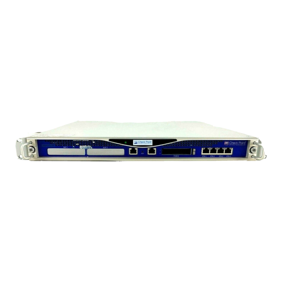
All manuals and user guides at all-guides.com About the Nokia IP390 Appliance Figure 2 Component Locations Rear View Power switch 00527 Power socket Built-In Gigabit Ethernet Ports The four built-in Gigabit Ethernet ports are located on the front of the appliance. -
Page 22: Pmc Expansion Slots
Nokia products only support NICs purchased from Nokia or Nokia-approved resellers. The Nokia Global Support Services group can provide support only for Nokia products that use Nokia-approved accessories. For sales or reseller information, contact a Nokia service provider listed in the “Nokia Contact Information”... -
Page 23: System Status Leds
All manuals and user guides at all-guides.com About the Nokia IP390 Appliance System Status LEDs You can monitor the basic operation of the appliance and NICs by checking their status LEDs. The system status LEDs are located on the front... -
Page 24: Managing The Appliance
“Using Nokia Network Voyager” on page 45. The IPSO command-line interface (CLI)—an SSHv2-secured interface that enables you to easily configure Nokia IP appliances from the command line. Everything that you can accomplish with Network Voyager—manage, monitor, and configure the IP390 appliance—you can also accomplish with the CLI. -
Page 25: Logging Options
All manuals and user guides at all-guides.com Logging Options Logging Options The IP390 supports two options for storing local system log files, as described in the following topics: Using Hard-Disk Drives for Logging Using a Flash-Memory PC Card for Logging Note You can use only one device for logging (whether it’s a hard-disk drive or flash-memory PC card) at a time. -
Page 26: Site Requirements, Warnings, And Cautions
Nokia customer support site listed in “Nokia Contact Information” on page 3. Site Requirements, Warnings, and Cautions Before you install a Nokia appliance, ensure that your computer room or wiring closet conforms to the environmental specifications listed in Chapter A, “Technical Specifications.” Warning... -
Page 27: Software Requirements
The Nokia appliance supports the following operating system and applications: Nokia operating system software requirements—IPSO v4.1 or later Check Point VPN-1 versions compatible with the version of Nokia IPSO you are using For information about updates to the software requirements or additional... - Page 28 All manuals and user guides at all-guides.com Overview Therefore, to help prevent damage to the environment, Nokia encourages you to dispose of these devices in an environmentally-friendly manner. The following resources are available to you to help with equipment-disposal decisions:...
-
Page 29: Installing The Nokia Ip390 Appliance
All manuals and user guides at all-guides.com Installing the Nokia IP390, 105i & 105s Appliance This chapter describes how to install the Nokia appliance. The following topics are covered: Before You Begin Rack Mounting the Appliance Connecting Power Connecting to the Console or Auxiliary Port... -
Page 30: Rack Mounting The Appliance
The appliance mounts in a standard 19-inch rack with four mounting screws as Figure 6 shows. Note To avoid damaging your equipment, Nokia recommends that you use all four rack-mounting screws when you install your appliance on the rack. Figure 6 Mounting Screws Location IP390 00525 Mounting screw slots IP390, 105i &... -
Page 31: Connecting Power
All manuals and user guides at all-guides.com Connecting Power Two mounting positions are available allowing you to mount the unit either flush with the rack, or two inches forward of the rack. Figure 7 Adjustable Mounting Brackets Brackets located for IP 3 flush with rack installation... -
Page 32: Connecting To The Console Or Auxiliary Port
Connecting to the Console or Auxiliary Port If you do not use DHCP to perform the initial configuration of your Nokia IP390 appliance, you must use a serial console connection (RJ-45 null-modem cable included). For information about using DHCP for initial configurations, see Chapter 3, “Performing the Initial Configuration.”... - Page 33 2. Connect the other end of the cable to the VT100 console or to a system running a terminal-emulation program. The cable that Nokia provides with appliances includes a latching mechanism used to secure the cable to the console port or auxiliary port of your appliance.
- Page 34 Installing the Nokia IP390 Appliance Note To use the cable for modem connections from the auxiliary port, you need to order a modem cable kit. For information about contacting Nokia to order the kit, see “Nokia Contact Information” on page 3.
- Page 35 All manuals and user guides at all-guides.com Connecting to the Console or Auxiliary Port appliance, pull back on the boot to release the latch, and pull the connector out of the receptacle. To connect the cable 1 + 2 = Pull boot Push cable To disconnect the cable...
-
Page 36: Console Port
All manuals and user guides at all-guides.com Installing the Nokia Appliance adaptor). The DB-9 adapter is provided with the cable. The DB-25 adaptor is provided with Nokia modem cable kits for the appliance. 00552 DB-25 male adapter DB-9 female adapter... -
Page 37: Auxiliary Port
All manuals and user guides at all-guides.com Connecting to the Console or Auxiliary Port RJ-45 to DB-9 Console Port RJ-45 to RJ-45 Rollover Terminal (DTE) Cable Adapter Console Device The console cable provided with the IP390 is comprised of two parts: 6-foot rollover cable with RJ-45 terminations RJ-45 to DB-9 adapter On the opposite end of the console cable, connect the RJ-45 to the DB-9... -
Page 38: Connecting To Network Interfaces
All manuals and user guides at all-guides.com Installing the Nokia IP390 Appliance Auxiliary Port RJ-45 to RJ-45 Rollover RJ-45 to DB-25 (DTE) Cable Modem Adapter Modem Connecting to Network Interfaces Connect at least one network interface to use as the Network Voyager system management interface. - Page 39 Connecting to Network Interfaces Note All Nokia copper Gigabit Ethernet NICs support cable auto-sensing. You can use a straight-through or crossover cable to connect the NIC to a Gigabit Ethernet hub or switch, or to connect directly to a host.
- Page 40 All manuals and user guides at all-guides.com Installing the Nokia IP390 Appliance IP390, 105i & 105s Security Platform Installation Guide...
-
Page 41: Performing The Initial Configuration
All manuals and user guides at all-guides.com Performing the Initial Configuration The first time you turn power on to a Nokia appliance, the initial configuration process begins. This process enables you to configure the network settings and provides access to the admin account. -
Page 42: Using A Console Connection
What is the hostname? What is the admin password? Will you use Nokia Network Voyager for subsequent configuration? Which interface will you use? What is the assigned IP address and masklength? - Page 43 The fans on the back of the appliance turn on when you press the power switch. Verify that the fans are running after you press the switch. Check the power LED on the front panel of the appliance (the Nokia logo) to ensure that the power supply is operating correctly. The power LED should be illuminated.
- Page 44 If you verify the console connections and still do not see either the BOOTMGR> or Hostname? prompts, verify that the terminal or terminal emulator program settings are correct. If the settings are correct, contact your Nokia service provider as listed in “Nokia Contact Information”...
-
Page 45: Using Nokia Network Voyager
All manuals and user guides at all-guides.com Using Nokia Network Voyager Using Nokia Network Voyager Use Nokia Network Voyager to configure and monitor your appliance. For additional information about how to use Network Voyager, see “Viewing Nokia IPSO Documentation by Using Nokia Network Voyager”... -
Page 46: Viewing Nokia Ipso Documentation By Using Nokia Network
You do this be navigating to Configuration > System Configuration > Packages > Manage Packages and turning the package on. The following documentation is available in Nokia Network Voyager and is accessible from the Network Voyager interface, as shown in Figure Nokia Network Voyager Reference Guide—This guide is the... -
Page 47: Using The Command-Line Interface
Link to inline help (context sensitive help) Using the Command-Line Interface You can also use the Nokia IPSO command-line interface (CLI) to manage and configure Nokia IP appliances from the command line. Everything that you can accomplish with Network Voyager you can also do with the CLI. - Page 48 That is, you can view configuration settings, but you cannot change them. You can now execute CLI commands from the CLI shell and the Nokia IPSO shell. The Nokia IPSO shell is what you see when you initially log on to the appliance. Execute from...
-
Page 49: Using Nokia Horizon Manager
All manuals and user guides at all-guides.com Using Nokia Horizon Manager For more information about how to access and use the CLI, see the Nokia CLI Reference Guide for the version of Nokia IPSO you are using. Using Nokia Horizon Manager Nokia Horizon Manager is an extension of the Network Voyager management functionality. - Page 50 All manuals and user guides at all-guides.com Performing the Initial Configuration IP390, 105i & 105s Security Platform Installation Guide...
-
Page 51: Installing And Replacing Network Interface Cards
All manuals and user guides at all-guides.com Installing and Replacing Network Interface Cards Your appliance comes with any network interface cards (NICs) you ordered already installed. This chapter describes how to remove, add, or replace NICs later if it becomes necessary. The following topics are covered: Deactivating Configured Interfaces Removing, Installing, and Replacing NICs... -
Page 52: Deactivating Configured Interfaces
If you do not deactivate the interfaces before removing the NIC, you may have to reinstall the NIC to deactivate its logical and physical interfaces in Network Voyager. For information about how to access Network Voyager, see “Using Nokia Network Voyager” on page 45. Removing, Installing, and Replacing NICs... -
Page 53: Before You Start
All manuals and user guides at all-guides.com Removing, Installing, and Replacing NICs Before You Start To remove, install, or replace a Nokia NIC, you need the following: A Phillips-head screwdriver Physical access to the appliance Access to the appliance by using Nokia Network Voyager or the CLI... - Page 54 All manuals and user guides at all-guides.com Installing and Replacing Network Interface Cards 2. Use your fingers or a screwdriver to loosen the retaining screws that hold the chassis tray assembly. IP390 00525 Chassis tray assembly retaining screws 3. Gently pull the chassis tray assembly forward to expose the NIC connectors.
- Page 55 All manuals and user guides at all-guides.com Removing, Installing, and Replacing NICs 4. From underneath the chassis tray assembly, remove the bezel retaining screws. 00529 If you are installing a NIC in an unoccupied slot, remove the blank bezel that occupies the space in the appliance front panel, retain it for future use, and proceed to step 5.
- Page 56 All manuals and user guides at all-guides.com Installing and Replacing Network Interface Cards 6. Remove the NIC by lifting the back of the NIC away from the chassis tray assembly and pulling the NIC gently away from the front panel. 00533 7.
- Page 57 All manuals and user guides at all-guides.com Removing, Installing, and Replacing NICs If you are installing or replacing a NIC, insert the NIC. a. Insert the NIC bezel into the front panel. 00532 b. Gently push the back of the NIC down toward the chassis tray assembly.
- Page 58 All manuals and user guides at all-guides.com Installing and Replacing Network Interface Cards 9. From beneath the chassis tray assembly, screw in the bezel retaining screws. 00528 10. Slide the chassis tray assembly back into the appliance until it clicks into place.
-
Page 59: Configuring And Activating Interfaces
NIC. For information about how to access Network Voyager and the related reference materials, see “Using Nokia Network Voyager” on page 45. Monitoring Network Interface Cards You can asses the general operating condition of the NICs in your appliance by looking at the LED status indicators on the NICs. - Page 60 Use Network Voyager to access detailed port information. For information about accessing Network Voyager, see “Using Nokia Network Voyager” page 45. You can also use the Nokia IPSO tcpdump command to examine the track on a specific port. IP390, 105i & 105s Security Platform Installation Guide...
-
Page 61: Connecting Pmc Network Interface Cards
(ESD) damage by making sure you are properly grounded before you touch any electronic component. Four-Port 10/100 Mbps Ethernet NICs The IP390 appliance supports Nokia-approved, four-port UTP5 dual-mode 10-Mbps and 100-Mbps Ethernet NICs. IP390, 105i & 105s Security Platform Installation Guide... -
Page 62: Ethernet Nic Features
All manuals and user guides at all-guides.com Connecting PMC Network Interface Cards When you purchase an Ethernet NIC with your appliance, the NIC is installed before the appliance is delivered to you. For information on how to add or replace a NIC later, see Chapter 4, “Installing and Replacing Network Interface Cards.”... -
Page 63: Ethernet Nic Connectors And Cables
All manuals and user guides at all-guides.com Four-Port 10/100 Mbps Ethernet NICs Ethernet NIC Connectors and Cables The connectors on the Ethernet NIC are RJ-45 connectors: To connect to a 10-Mbps or 100-Mbps hub, use a straight-through RJ-45 cable. To connect directly to a host, use an RJ-45 crossover cable. Use IEEE 802.3 10BASE-T, 100BASE-TX unshielded twisted-pair, full-duplex or half-duplex cable. -
Page 64: Figure 11 Output Connector For The Ethernet Cable
All manuals and user guides at all-guides.com Connecting PMC Network Interface Cards Figure 11 Output Connector for the Ethernet Cable Pin# Assignment 00270 Figure 12 shows the pin assignments for the RJ-45 cross-over cable. Figure 12 Ethernet Crossover-Cable Pin Connections 00017.1 You can also use cables intended for Gigabit Ethernet NIC connections for your Ethernet NIC connections, as shown in... -
Page 65: Two-Port Copper Gigabit Ethernet Network Interface Card
Copper Gigabit Ethernet NICs you use in appliances need to be the Version 2 type, as indicated on the right end of the NIC faceplate. These NICs are sold by Nokia under the order code NIF4425. Copper Gigabit Ethernet NIC Features... -
Page 66: Copper Gigabit Ethernet Connectors And Cables
(Cat 5 type cable, or as required by your network configuration). Note All Nokia copper Gigabit Ethernet NICs support cable auto-sensing. You can use a straight-through or crossover cable to connect the NIC to a Gigabit Ethernet hub or switch, or to connect directly to a host. -
Page 67: Figure 15 Copper Gigabit Ethernet Cable Connector Output Pin
All manuals and user guides at all-guides.com Two-Port Copper Gigabit Ethernet Network Interface Card Figure 15 Copper Gigabit Ethernet Cable Connector Output Pin Assignments Gigabit Ethernet 10/100 Mbps Pin# Assignment Assignment 00270 BI_DA+ BI_DA- BI_DB+ BI_DC+ BI_DC- BI_DB- BI_DD+ BI_DD- To connect directly to a host, use an RJ-45 crossover cable wired as Figure 16 shows. -
Page 68: Two-Port Fiber-Optic Gigabit Ethernet Network Interface Card
Packet tracing for analysis through tcpdump Compliance with IEEE 802.3z Gigabit Ethernet specification You can configure and monitor Ethernet interfaces with Nokia Network Voyager, the Web-based element management interface to Nokia IP appliances. Specifically, you set the port speed and full-duplex mode with Network Voyager. -
Page 69: Fiber-Optic Gigabit Ethernet Connectors And Cables
All manuals and user guides at all-guides.com Two-Port Fiber-Optic Gigabit Ethernet Network Interface Card Figure 17 Two-Port Fiber-Optic Gigabit Ethernet NIC Link LEDs (solid green) Activity LEDs (blinking yellow) 00206 Ports Fiber-Optic Gigabit Ethernet Connectors and Cables To connect the two-port Gigabit Ethernet NIC to other network components, use a multimode, fiber-optic cable with an LC connector for each NIC interface. - Page 70 All manuals and user guides at all-guides.com Connecting PMC Network Interface Cards IP390, 105i & 105s Security Platform Installation Guide...
-
Page 71: Installing And Replacing Other Components
All manuals and user guides at all-guides.com Installing and Replacing Other Components This chapter provides information on how to add or replace user serviceable items other than network interface cards (NICs) in your appliance. The following topics are covered: Replacing the Compact Flash Memory Card Installing a Flash-Memory PC Card Installing or Replacing a Hard-Disk Drive Configuring a PC Card or Hard-Disk Drive for Logging... -
Page 72: Replacing The Compact Flash Memory Card
Replacing the Compact Flash Memory Card The compact flash memory card stores the Nokia IPSO operating system and the boot manager program. Use the internal compact flash memory to boot the system and install the Nokia IPSO operating system on the compact flash memory card. -
Page 73: Figure 18 Compact Flash Memory Card Slot
All manuals and user guides at all-guides.com Replacing the Compact Flash Memory Card Figure 18 Compact Flash Memory Card Slot IP 39 00550 Caution To protect the appliance and the compact flash memory from electrostatic discharge damage, make sure you are properly grounded before you touch these components. - Page 74 All manuals and user guides at all-guides.com Installing and Replacing Other Components Note Because power to an appliance is automatically disconnected when the chassis tray assembly is opened, you do not need to manually disconnect the power for this procedure. Any servicing of the unit, however, should be completed with the chassis tray assembly fully removed from the appliance.
- Page 75 All manuals and user guides at all-guides.com Replacing the Compact Flash Memory Card 4. Slide the chassis tray assembly forward and completely remove the chassis to expose the motherboard components. IP 3 00537 5. Place the chassis tray assembly on a table top. 6.
-
Page 76: Installing A Flash-Memory Pc Card
10. Turn on the power supply at the back of the appliance. Installing a Flash-Memory PC Card You can use the flash-memory PC card to store local system logs, Nokia IPSO images, and configuration files.The appliance has two PCMCIA slots that can support a flash-memory PC card having a capacity of 1 GB or higher. -
Page 77: Transferring Files With The Flash-Memory Pc Card
Transferring Files with the Flash-Memory PC Card You can copy configuration files between the internal compact flash memory and the flash-memory PC card. If you do not use Nokia Network Voyager to configure the flash-memory PC card as an optional disk, you must mount the flash-memory PC card when you insert it in the PC-card slot, and you must unmount the flash-memory PC card before you remove it. -
Page 78: Installing Or Replacing A Hard-Disk Drive
Back up your files to a remote system on a regular basis. For back up and restore procedures, see the Getting Started Guide and Release Notes for the version of Nokia IPSO you are using. IP390, 105i & 105s Security Platform Installation Guide... -
Page 79: Before You Start
Before You Start To install the hard-disk drive in your appliance, you need the following: Physical access to the appliance A Nokia-approved hard-disk drive Access to the appliance through Network Voyager A Phillips-head screwdriver A torque screwdriver capable of a 69.4ozf*in (5kgf*cm) setting... - Page 80 To install or replace a hard-disk drive 1. Use Network Voyager to shut the appliance down. For information about how to access Network Voyager, see “Using Nokia Network Voyager” on page 45. 2. Loosen the retaining screws that hold the chassis tray assembly.
- Page 81 All manuals and user guides at all-guides.com Installing or Replacing a Hard-Disk Drive chassis body and care should be taken when working on the power supply or power supply wiring without disconnecting the power cord. 4. If a you are replacing a hard-disk drive, remove the retaining screws that hold the hard-disk drive unit from the bottom of the chassis tray assembly.
- Page 82 All manuals and user guides at all-guides.com Installing and Replacing Other Components 5. Insert the hard-disk drive unit. 00536 Note Push the hard-disk drive gently into place. Take care to align the connectors correctly as the connectors are not keyed. IP390, 105i &...
- Page 83 All manuals and user guides at all-guides.com Installing or Replacing a Hard-Disk Drive 6. Tighten the retaining screws that holds the hard-disk drive into place. 00535 7. Slide the chassis tray assembly back into the appliance until it clicks into place.
-
Page 84: Configuring A Pc Card Or Hard-Disk Drive For Logging
Nokia Network Voyager Reference Guide and the CLI Reference Guide for Nokia IPSO contain instructions for configuring a Nokia appliance to store Nokia IPSO log messages on the disk. This section explains how to configure an optional disk and configure it to store Check Point log messages on an IP390. - Page 85 The delay is longer with devices of larger capacity. 8. When the message appears, click Reboot, Shutdown System. 9. Reboot the appliance. 10. When the appliance has rebooted, log into it and start Nokia Network Voyager. 11. Navigate to the System Logging configuration page.
-
Page 86: Replacing Or Upgrading Memory
All manuals and user guides at all-guides.com Installing and Replacing Other Components For more information about storing Nokia IPSO system logs, see the Nokia Network Voyager Reference Guide or the CLI Reference Guide for the version of Nokia IPSO you are using. -
Page 87: Before You Start
Before You Start To upgrade or replace the memory in your appliance, you need the following: Physical access to the appliance Nokia memory upgrade kit and accompanying documentation Network or console access to the appliance Caution To protect the appliance and the memory modules from electrostatic discharge (ESD), make sure you are properly grounded before you touch these components. - Page 88 All manuals and user guides at all-guides.com Installing and Replacing Other Components To add or replace DIMMs 1. Use Network Voyager or the CLI to halt the appliance. To use Network Voyager to shut the appliance down, select System > Configuration > Reboot or Shutdown > Halt. To use the CLI to do this, enter halt at the prompt.
- Page 89 All manuals and user guides at all-guides.com Replacing or Upgrading Memory 4. Remove any memory module necessary by pressing the two retaining clips outward and carefully pulling each DIMM upward as the following figure shows. IP 39 00545 You might need to pull opposite ends of the DIMM alternately to gradually free it from the contact pins.
- Page 90 All manuals and user guides at all-guides.com Installing and Replacing Other Components The top of the DIMM is smooth. The bottom edge has three different length sets of contacts, which mate with the slots on the socket. Be sure the contacts and slots are properly aligned before you insert the DIMM. IP 39 00544 The retaining clips move into the lock position as you press the DIMM...
- Page 91 All manuals and user guides at all-guides.com Replacing or Upgrading Memory 6. Slide the chassis tray assembly back into the appliance until it clicks into place. IP 3 00538 The appliance automatically restarts when the chassis tray assembly clicks into place. 7.
- Page 92 All manuals and user guides at all-guides.com Installing and Replacing Other Components IP390, 105i & 105s Security Platform Installation Guide...
-
Page 93: Troubleshooting
All manuals and user guides at all-guides.com Troubleshooting This chapter provides troubleshooting tips, problems, and solutions related to IP390 appliance installations. General Troubleshooting Information The information in this section relates to non-routing problems. For information about how to troubleshoot routing problems, see “Troubleshooting Routing Problems”... - Page 94 3. Problem Database is corrupt. Solution Return to default settings according to the instructions included in the instructions for resetting the default password, or contact the Nokia customer support site listed in “Nokia Contact Information” on page 3.
- Page 95 All manuals and user guides at all-guides.com General Troubleshooting Information To reset the admin password to a default value Note You must have local serial access to your appliance console to perform this procedure. With a keyboard and monitor directly connected to the appliance, the boot: prompt does not appear, and you cannot perform this procedure.
- Page 96 For information about how to complete the full installation procedure, see the current release notes. The release notes are located on the Nokia customer support Web site as listed in the “Nokia Contact Information”...
- Page 97 Do Not See Interfaces that Should be Present Problem Local appliance ports do not appear. Solution Your NIC might be defective. Contact the appropriate Nokia customer support site as listed in “Nokia Contact Information”...
- Page 98 All manuals and user guides at all-guides.com Troubleshooting Common Ethernet Problems—Connectivity with Attached Device Problem No link light. Solution You might have used the wrong cable. Use a crossover cable between an IP390 appliance and a host, and a straight-through cable between an appliance and a hub.
- Page 99 IP address you are attempting to ping, use Network Voyager to delete the invalid entry. For information about how to access Network Voyager and the related reference materials, see “Using Nokia Network Voyager” on page 45. To delete the invalid entry 1. Click Config.
- Page 100 All manuals and user guides at all-guides.com Troubleshooting information about how to use the tcpdump command, see the Nokia Network Voyager Reference Guide. Under Routing Options in the Routing Configuration section in Network Voyager, you can also enable several types of trace options for DVMRP.
- Page 101 Problem The MTU size is not 1500 (for Ethernet interfaces) or 16018 (for Gigabit Ethernet interfaces). Solution The MTU size must be 1500 (for Ethernet interfaces) or 16018 (for Gigabit Ethernet interfaces). Nokia does not support larger MTU sizes. Appliance Not Receiving Power Problem Power cord is not properly plugged in.
- Page 102 All manuals and user guides at all-guides.com Troubleshooting Appliance locks up after you upgrade Nokia IPSO with a console connection. No error messages appear, but the appliance stops responding to console and network. Problem During the upgrade process, some of the environment variables might not have updated correctly.
-
Page 103: Troubleshooting Routing Problems
ICLID (IPSRD command-line interface daemon) command. An example use of the ICLID command is shown below. For information about the ICLID command, see the Nokia Network Voyager Reference Guide. For information about how to access Network Voyager and the related reference materials, see “Using Nokia Network Voyager”... - Page 104 All manuals and user guides at all-guides.com Troubleshooting Note Adding a question mark (?) after any command provides additional command options. Typing a question mark (?) at a prompt provides a list of available commands. hostname[admin]# iclid hostname | IP address> hostname | IP address>...
- Page 105 All manuals and user guides at all-guides.com Troubleshooting Routing Problems For more information about how to use the tcpdump command, see the Nokia Network Voyager Reference Guide. Under routing options in Network Voyager, you can also enable several types of trace options for OSPF. These traces are logged in /var/tmp/ipsrd.log...
- Page 106 All manuals and user guides at all-guides.com Troubleshooting For more information about how to use the tcpdump command, see the Nokia Network Voyager Reference Guide. Under routing options in Network Voyager, you can also enable several types of trace options for routing information protocol (RIP). These traces are logged in /var/tmp/ipsrd.log...
- Page 107 All manuals and user guides at all-guides.com Troubleshooting Routing Problems Problem Routing protocol is not functioning properly. Solution to ensure that each routing protocol is functioning properly, see “Common Problems with OSPF” on page 104 and “Common Problems with RIP” on page 105.
- Page 108 All manuals and user guides at all-guides.com Troubleshooting IP390, 105i & 105s Security Platform Installation Guide...
-
Page 109: A Technical Specifications
All manuals and user guides at all-guides.com Technical Specifications Physical Dimensions Dimensions Height: 1.75 in. (4.45 cm) Width: 17 in. (44 cm) 19 in. (48 cm) rack mountable Depth: 16.12 in. (40.94 cm) Weight 17 lbs. (7.7 kg) base system Space Requirements The appliance is designed for front-screw mounting in a 19-inch rack. -
Page 110: Operating Temperature
Do not place objects over the ventilation holes on the appliance. The appliance might overheat and become damaged. Operating Temperature The operating temperature range for the Nokia appliance is 0° C to 45° C (32° F to 113° F). NIC Interfaces... -
Page 111: B Compliance Information
Declaration of Conformity Compliance Statements FCC Notice (US) Declaration of Conformity According to ISO/IEC Guide 22 and EN 45014: Manufacturer’s Name: Nokia Inc. Manufacturer’s Address: 313 Fairchild Drive Mountain View, CA 94043-2215 declares that the product: Product Name: IP390, 105i & 105s... - Page 112 All manuals and user guides at all-guides.com Compliance Information Serial Number: 1 to 100,000 Date First Applied: 2006 conforms to the following standards: Safety: EN60950-1:2001+A11; IEC60950-1:2001; UL60950, Third Edition:2000; CAN/CSA-C22.2 No.60950:2000. EMC: EN55024 1998, EN55022A 1998, EN61000-3-2, EN61000-3-3 Supplementary information: Pursuant to directive 1999/5/EC this product complies with the requirements of the Low Voltage Directive 73/23/EEC and the EMC Directive 89/336/EEC with Amendment 93/68/EEC.
-
Page 113: Compliance Statements
All manuals and user guides at all-guides.com Compliance Statements Compliance Statements This hardware complies with the standards listed in this section. Emissions Standards FCC Part 15 Subpart B Class A US/Canada EN55022 (CISPR 22 Class A) European Community (CE) Immunity Standards EN55024 European Community (CE) EN61000-4-2... -
Page 114: Fcc Notice (Us)
All manuals and user guides at all-guides.com Compliance Information FCC Notice (US) This device has been tested and found to comply with the limits for a Class A digital device, pursuant to Part 15 of the FCC Rules. These limits are designed to provide reasonable protection against harmful interference in a residential installation. -
Page 115: Index
(CLI) pin assignments 36 overview 24 using the 47 compact flash memory card deactivating NICs 52 Nokia IPSO storage 20 declaration of conformity 111 replacing the 72 depth specification 109 compliance information 111 DHCP server 41 declaration of conformity 111... - Page 116 All manuals and user guides at all-guides.com installing hard-disk drive, a 78 end-of-life information 27 NICs 52 equipment disposal 28 IP routing 19 Ethernet cable output connector 64 Ethernet crossover-cable pin connections 64 Ethernet NICs cable pin assignments 64 LEDs connecting to 63 Ethernet NIC 62 front panel 62...
- Page 117 110 overview 24 physical dimensions 109 using 45 space requirements 109 weight 109 width 109 opening Nokia Network Voyager 45 specifications operating temperature specification 110 network interfaces 110 output connector technical 109 Ethernet NIC 64 system logging with hard-disk drive 84...
- Page 118 All manuals and user guides at all-guides.com ventilation requirements 26 weight specification 109 width specification 109 Index - 118 IP390, 105i & 105s Security Platform Installation Guide...