
Related Manuals for Nokia Check Point IP2450


Summary of Contents for Nokia Check Point IP2450
- Page 1 Check Point IP2450 Security Platform Installation Guide Part No. N450000897 Rev 001 Published March 2009...
-
Page 2: Check Point Contact Information
For additional technical information about Check Point products, and for the latest version of this document, see the Check Point Support Center at http://support.checkpoint.com/. Check Point is engaged in a continuous effort to improve its documentation. Please help us by sending your comments to: cp_techpub_feedback@checkpoint.com Check Point IP2450 Security Platform Installation Guide... -
Page 3: Table Of Contents
Overview ............15 About the Check Point IP2450 Security Platform......15 Managing the Check Point IP2450 Security Platform . - Page 4 Reconfiguring Interfaces ......... . 80 Check Point IP2450 Security Platform Installation Guide...
- Page 5 Index ............133 Check Point IP2450 Security Platform Installation Guide...
- Page 6 Check Point IP2450 Security Platform Installation Guide...
- Page 7 Figure 2 Built-in Gigabit Ethernet Ports Details ......18 Figure 3 Check Point IP2450 Appliance System Status LEDs ....20 Figure 4 Hard-Disk Drive Front Pane .
- Page 8 Check Point IP2450 Security Platform Installation Guide...
- Page 9 Table 5 Power Supply Status LEDs ........25 Table 6 Check Point IP2450 Disk-Based Security Platform Software Requirements Table 7 Check Point IP2450 Flash-Based Security Platform Software Requirements Table 8 NIC PCI Frequency .
- Page 10 Check Point IP2450 Security Platform Installation Guide...
-
Page 11: About This Guide
About this Guide This manual provides information for the installation and use of the Check Point IP2450 security platforms. Installation and maintenance should be performed by experienced technicians or Check Point-approved service providers only. This preface provides the following information:... -
Page 12: Conventions This Guide Uses
Keys that you press simultaneously are linked by a plus sign (+): Press Ctrl + Alt + Del. Menu commands Menu commands are separated by a greater than sign (>): Choose File > Open. Check Point IP2450 Security Platform Installation Guide... - Page 13 • Emphasizes a point or denotes new terms at the place where they Italics are defined in the text. • Indicates an external book title reference. • Indicates a variable in a command: delete interface if_name Check Point IP2450 Security Platform Installation Guide...
- Page 14 About this Guide Check Point IP2450 Security Platform Installation Guide...
-
Page 15: Overview
Overview This chapter provides an overview of the Check Point IP2450 security platform and the requirements for its use. The following topics are covered: About the Check Point IP2450 Security Platform Managing the Check Point IP2450 Security Platform Check Point IP2450 Security Platform Overview... -
Page 16: Managing The Check Point Ip2450 Security Platform
Managing the Check Point IP2450 Security Platform You can manage the Check Point IP2450 security platform by using the following interfaces: Check Point Network Voyager for IP appliances—an SSL-secured, Web-based element management interface to Check Point IP security platforms. Check Point Network Voyager is preinstalled on the IP2450 security platform and enabled through the Check Point IPSO operating system. -
Page 17: Check Point Ip2450 Security Platform Overview
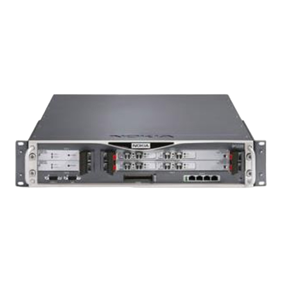
For information about how to obtain Check Point Horizon Manager, see the Check Point Web site at www.checkpoint.com. Check Point IP2450 Security Platform Overview Figure 1 shows the component locations for the Check Point IP2450 security platform. Figure 1 Component Locations Front View Dual 6U PMC carrier System status LEDs... -
Page 18: Expansion Slots
Table 2 Pin Assignments for Console Connector and Console Cable Console Port RJ-45 to DB-9 (DTE) RJ-45 to RJ-45 Rollover Cable Terminal Adapter Console Device Signal RJ-45 Pin RJ-45 Pin DB-9 Pin Signal Check Point IP2450 Security Platform Installation Guide... -
Page 19: Auxiliary Port
Radicom model V92MB-U-E, and you must be using Check Point IPSO 6.1 or greater. System Status LEDs You can visually monitor the status of the Check Point IP2450 appliance by checking the system status LEDs. The system status LEDs are located on the center of the front panel, as shown in Figure... -
Page 20: Figure 3 Check Point Ip2450 Appliance System Status Leds
Overview Figure 3 Check Point IP2450 Appliance System Status LEDs Warning (yellow) System OK (green) Fault (red) SLOT 1 SUB SLOT 1 SUB SLOT 2 FIO CARRIER POWER HOT SWAP LINK LINK LINK LINK READY REQUEST SUB SLOT 1 SUB SLOT 2... -
Page 21: Hard-Disk Drives
You can, if necessary, configure a RAID volume with the Check Point IPSO boot manager. The following actions are available to you under the boot manager raid command: disable enable create delete activate deactivate Check Point IP2450 Security Platform Installation Guide... -
Page 22: Hard-Disk Drive Hot Swap Feature
To avoid damage to the ejector and locking lever, loosen the two retaining screws before you remove the hard-disk drive. Once screw is located behind the ejector and locking lever, and the other screw is on the opposite side. Check Point IP2450 Security Platform Installation Guide... -
Page 23: Table 4 Hard-Disk Drive Leds
• The system is testing the hard-disk drive. Note Do not remove the hard-disk drive if the Status LED is blink- ing green or if the Hot Swap Ready LED is not illuminated solid blue. Check Point IP2450 Security Platform Installation Guide... -
Page 24: Power Supplies And Fan Unit
Fan unit Power Supplies The Check Point IP2450 appliance supports up to two power supplies for power sharing and redundancy. The IP2450 comes with two power supplies as the standard package. The power supplies are hot swappable and perform load sharing while two active power supplies are installed, increasing the life of the power supplies. -
Page 25: Table 5 Power Supply Status Leds
After the internal temperature returns to normal, power will be turned back on. PWR OK Green Power is on and the power supply is functioning properly. Check Point IP2450 Security Platform Installation Guide... -
Page 26: Fan Unit
Warning To reduce the risk of fire, electric shock, and injury when you use telephone equipment, follow basic safety precautions. Do not use the product near water. Check Point IP2450 Security Platform Installation Guide... -
Page 27: Software Requirements
Software Requirements Table 6 Table 7 describe operating system and applications requirements for the Check Point IP2450 appliances. Table 6 Check Point IP2450 Disk-Based Security Platform Software Requirements Check Point Platform IPSO Version Software Check Point v4.2 or later... -
Page 28: Product Disposal
Overview Table 7 Check Point IP2450 Flash-Based Security Platform Software Requirements Check Point Platform IPSO Version Software Check Point v4.2 or later Check Point VPN-1 versions compatible with the version of Check IP2450 Point IPSO you are using For information about updates to the software requirements or additional applications that have... -
Page 29: Installing The Check Point Ip2450 Appliance
Installing the Check Point IP2450 Appliance This chapter describes how to install the Check Point IP2450 appliance. The following topics are discussed: Rack Mounting the Appliance Before You Begin Caution To help guard against electrostatic discharge damage, make sure you are properly grounded by using a grounding wrist strap and following the instructions provided with the wrist strap before you handle the components or open the appliance. -
Page 30: Before You Begin
Before You Begin To rack-mount the appliance, you need: Phillips-head screwdriver Disposable grounding wrist strap Suitable, grounded work surface on which to place the chassis tray assembly Check Point IP2450 Security Platform Installation Guide... - Page 31 (or other appropriate earth ground location that meets the specifications of your installation site) with the kep washer between the screw and cable lug. Torque the screw to 384 inch ounces Check Point IP2450 Security Platform Installation Guide...
- Page 32 Slowly pull the fan unit out of the chassis tray assembly toward the rear. 7 0 0 7 0 0 FA U O V E T E M P W R FA U O V E T E M P W R 00631 Check Point IP2450 Security Platform Installation Guide...
- Page 33 7 0 0 FA UL OV ER TE MP PW R 7 0 0 FA UL OV ER TE MP PW R 00630 4. Optionally, remove the chassis tray assembly from the appliance. Check Point IP2450 Security Platform Installation Guide...
- Page 34 SL OT RE QU ES T RE SE 00637 c. Place the chassis tray assembly on a properly grounded surface. 5. Adjust the front mounting brackets on the side of the appliance if necessary. Check Point IP2450 Security Platform Installation Guide...
- Page 35 8. Slide the chassis tray assembly back into the appliance until it clicks into place, and resecure the four chassis tray assembly retaining screws. 9. Reinstall the fan unit into the rear of the appliance. 10. Reinstall the power supplies. Check Point IP2450 Security Platform Installation Guide...
- Page 36 Installing the Check Point IP2450 Appliance Check Point IP2450 Security Platform Installation Guide...
-
Page 37: Performing The Initial Configuration
Performing the Initial Configuration The first time you turn on power to a Check Point IP2450 appliance, the initial configuration process begins. This process enables you to configure the network settings and provides access to the admin account. You can perform the initial configuration in two ways: Configure a DHCP server to provide the initial configuration information the first time the appliance is started. -
Page 38: Using A Console Connection
Performing the Initial Configuration Using a Console Connection If you do not use DHCP to perform the initial configuration of your Check Point IP2450 appliance, you must use a serial console connection (cable included). After you perform the initial configuration, you no longer need the console connection. -
Page 39: Connecting Power And Turning The Power On
The IP2450 appliance power supply automatically detects the input voltage (115 VAC or 220 VAC [85 to 264]) and configures itself appropriately. If the fans are not running, make sure: The power cord is properly connected. Check Point IP2450 Security Platform Installation Guide... -
Page 40: Performing The Initial Configuration
Fault LED illuminates. Performing the Initial Configuration If you do not use DHCP to perform the initial configuration of your Check Point IP2450 appliance, you must use a serial console connection (cable included). After you perform the initial configuration, you no longer need the console connection. - Page 41 2 would be: eth-s1/s2p1 The Ethernet management interface ports are numbered eth-s4p1 through eth-s4p4. After you complete the initial configuration, you can use Check Point Network Voyager to configure the remaining network ports. Check Point IP2450 Security Platform Installation Guide...
-
Page 42: Connecting Network Interfaces
Confirm the information you entered during the initial configuration and check that all cables are firmly connected. For more information, see the troubleshooting section in the installation guide for your appliance. Check Point IP2450 Security Platform Installation Guide... -
Page 43: Viewing Check Point Ipso Documentation By Using Check Point Network Voyager
Close button is available at the bottom of each online help window you view. Figure 10 Check Point Network Voyager Reference Access Points Link to complete user documentation Link to online help (context sensitive help) Check Point IP2450 Security Platform Installation Guide... -
Page 44: Using The Command-Line Interface
While Check Point Network Voyager provides the device administrator access to network configuration tasks (such as interface configuration and routing configuration) and security configuration tasks (such as user configuration and access configuration), Check Point Horizon Check Point IP2450 Security Platform Installation Guide... - Page 45 (MSP), or hosted applications service provider network (ASP). For information about how to obtain Check Point Horizon Manager or to learn more about the Check Point Horizon Manager, see the Check Point Web site at www.checkpoint.com. Check Point IP2450 Security Platform Installation Guide...
- Page 46 Performing the Initial Configuration Check Point IP2450 Security Platform Installation Guide...
-
Page 47: Installing And Replacing Network Interface Cards And Adp Modules
Installing and Replacing Network Interface Cards and ADP Modules The Check Point IP2450 appliance may come with one of the network interface cards (NICs) or Accelerated Data Path (ADP) modules that you ordered already installed. NICs or ADP modules installed in IP2450 slots 1 and 2 are housed in a 6U PMC carrier. NICs housed in 6U PMC carriers are hot swappable, but NICs in slots 3 and 4 and ADP modules are not, and you must power down your appliance to install or replace them. -
Page 48: Removing, Installing, And Replacing Nics And Adp Modules
Before you install a NIC, make sure that the rubber gasket around the front of the NIC is installed properly. To remove, install, or replace a NIC or ADP module, you need the following: Phillips-head screwdriver Check Point IP2450 Security Platform Installation Guide... - Page 49 Caution To avoid damage to the ejector and locking lever, loosen the retaining screw behind each ejector and locking lever before you remove the 6U PMC carrier or ADP module. Check Point IP2450 Security Platform Installation Guide...
- Page 50 R E S 00645 6. Continue to press or push the levers outward until the 6U PMC carrier or ADP module is released and extends slightly beyond the front panel of the IP2450. Check Point IP2450 Security Platform Installation Guide...
- Page 51 Note If you are installing a NIC in an unoccupied slot on the 6U PMC carrier, remove the blank bezel that covers the slot and retain it for future use. Proceed to step Check Point IP2450 Security Platform Installation Guide...
- Page 52 10. Locate and remove the two NIC retaining screws from the back of the NIC. 00312 11. Remove the NIC by lifting the back of the NIC away from the chassis tray assembly and pulling it gently away from the front panel. 00313.1 Check Point IP2450 Security Platform Installation Guide...
- Page 53 To reduce electromagnetic interference (EMI), a blank bezel needs to be installed in the place of any NIC you have removed. 13. From the top of the 6U PMC carrier, screw the NIC retaining screws into the standoffs on the back of the NIC. 00312 Check Point IP2450 Security Platform Installation Guide...
- Page 54 If you are installing a new or different NIC or ADP module, configure the new NIC or ADP module by using Check Point Network Voyager. For information about how to access Check Point Network Voyager, see “Using Check Point Network Voyager” on page 42. Check Point IP2450 Security Platform Installation Guide...
- Page 55 FIO CARRIER STATUS POWER LINK LINK POWER HOT SWAP ACTIVITY HOT SWAP HOT SWAP READY REQUEST HDD B SLOT 2 SLOT 3 SLOT 4 PC CARD RESET CONSOLE AUX2 00616.1 Chassis tray assembly screws Check Point IP2450 Security Platform Installation Guide...
- Page 56 RE QU SL OT ES T RE SE 00637 Slot 3 Slot 4 4. Remove the six screw that secure the metal shield above the two 6U PMC carriers and remove the shield. Check Point IP2450 Security Platform Installation Guide...
- Page 57 S L O S L O R E S Remove 6U PMC carriers 00654.1 6. Remove the two front bezel screws and remove the slot 3 or slot 4 filler panel or installed NIC. Check Point IP2450 Security Platform Installation Guide...
- Page 58 C O N S O L A U X A U X S L O S L O I P 2 4 5 0 S L O S L O R E S 00657.2 Check Point IP2450 Security Platform Installation Guide...
- Page 59 If you are installing a new or different NIC, configure the new NIC by using Check Point Network Voyager. For information about how to access Check Point Network Voyager, see “Using Check Point Network Voyager” on page 42. Check Point IP2450 Security Platform Installation Guide...
-
Page 60: Configuring And Activating Interfaces
Installing and Replacing Network Interface Cards and ADP Modules Configuring and Activating Interfaces The Check Point IP2450 appliance automatically detects any new interfaces when either 6U PMC carrier or ADP module is completely installed. Use Check Point Network Voyager to configure and activate the logical and physical interfaces on the NIC or ADP module. -
Page 61: About Ip2450 Appliance Network Interface Cards
About IP2450 Appliance Network Interface Cards This chapter describes the network interface cards available for the Check Point IP2450 appliance and how to connect those NICs to your network. The following NICs are described: Four-Port 10/100 Ethernet NICs Two-Port Fiber-Optic Gigabit Ethernet NICs... -
Page 62: Four-Port 10/100 Ethernet Nics
After the power is turned on and the cables are connected, the Ethernet link LEDs on both the IP2450 and on the remote equipment illuminate to indicate the connection. As data is transmitted, the activity LEDs on the appliance illuminate. Check Point IP2450 Security Platform Installation Guide... -
Page 63: Ethernet Nic Connectors And Cables
Figure 12 Output Connector for the Ethernet Cable Assignment TX + TX - 00270 RX + RX - Figure 13 shows the pin assignments for the RJ-45 cross-over cable. Figure 13 Ethernet Crossover-Cable Pin Connections 00017.1 Check Point IP2450 Security Platform Installation Guide... -
Page 64: Two-Port Fiber-Optic Gigabit Ethernet Nics
(1000 BASE-SX) fiber-optic Gigabit Ethernet NIC you can use in IP2450 appliance. Figure 14 PMC Two-Port Short-Range Gigabit Ethernet NIC Link LEDs (solid green) Activity LEDs (blinking amber) 00206 Ports Check Point IP2450 Security Platform Installation Guide... -
Page 65: Fiber-Optic Gigabit Ethernet Nic Connectors And Cables
6U PMC carrier units to get maximum system throughput. Each 6U PMC carrier unit has a separate PCI bus connection to the main system motherboard. In the configuration described here, each of the two fiber-optic two-port Gigabit Ethernet NICs access a separate PCI bus. Check Point IP2450 Security Platform Installation Guide... -
Page 66: Two-Port And Four-Port Copper Gigabit Ethernet Nic
About IP2450 Appliance Network Interface Cards Two-Port and Four-Port Copper Gigabit Ethernet NIC The Check Point IP2450 appliance supports Check Point-approved, two-port and four-port copper Gigabit Ethernet NICs installed on a 6U PMC carrier or in slot 3 (slot 4 is reserved for a four-port copper Gigabit Ethernet NIC and it is replaceable). -
Page 67: Performance Considerations
To connect to a hub, switch, or router, use a straight-through RJ-45 cable (Cat 5 type cable, or as required by your network configuration). Note Certain circumstances might require shielded Cat 5 Ethernet cables to meet Class B emissions requirements. Check Point IP2450 Security Platform Installation Guide... -
Page 68: Figure 18 Ethernet Cable Connector Output Pin Assignments
As data is transmitted or received, the activity LEDs on the appliance illuminate. To connect the IP2450 to other network components, you can order appropriate adapter cables separately from a cable vendor of your choice. Check Point IP2450 Security Platform Installation Guide... -
Page 69: About Ip2450 Appliance Adp Services Modules
About IP2450 Appliance ADP Services Modules This chapter describes the Accelerated Data Path (ADP) services modules available for the Check Point IP2450 appliance and how to connect those modules to your network. It includes the following sections: Installing and Replacing ADP Modules... -
Page 70: Installing And Replacing Adp Modules
To install a Check Point ADP module, you need the following: A Phillips-head screwdriver Physical access to the appliance Access to the appliance by using Check Point Network Voyager or the CLI A suitable, grounded work surface The ADP module kit Check Point IP2450 Security Platform Installation Guide... - Page 71 Note Hot Swap switch functionality is not supported by Check Point IPSO at the time of this guide’s publication. The RDY LED, however, illuminates during booting and then turns off. Check Point IP2450 Security Platform Installation Guide...
- Page 72 ADP module port is connected to a switch. This likely indicates that the switch is sending ARP (address restoration protocol) requests to the port, and no traffic is present. Check Point IP2450 Security Platform Installation Guide...
-
Page 73: Figure 20 Adp Module Front Panel Details And Led Information
Link 1000 Mbps: Green (solid) Ejector and locking levers Three-port fiber10 Gigabit Ethernet ADP module Link 10 Gbps: Green (solid) Activity Orange (blinking) ADP 10G CARD HOT SWAP 00658 Ejector and locking levers Check Point IP2450 Security Platform Installation Guide... -
Page 74: Using Adp Transceivers In Adp Modules
Note that if you install any ADP transceivers that are not supported by Check Point, they are not recognized by Check Point IPSO; the system rejects the transceivers and includes them in a list Check Point IP2450 Security Platform Installation Guide... -
Page 75: Identifying Adp Module And Transceiver Types With Latch Lever Color Codes
10 Gigabit Ethernet long range Blue Check Point ADP Module LED Reference Information All Check Point IP2450 ADP modules provide two LEDs for each port to indicate Link and Activity status. For information about the LEDs, see Figure 20 on page 73. -
Page 76: Configuring Check Point Ipso For Ip2450 Adp Interfaces
ADP module interface naming conventions differ from those for PMC NICs The twelve ports on your ADP module are named as follows: For slot 1: eth-s1p1, eth-s1p2, eth-s1p3, eth-s1p4, eth-s1p5, eth-s1p6, eth-s1p7, eth-s1p8, eth-s1p9, eth- s1p10, eth-s1p11, eth-s1p12 For slot 2: Check Point IP2450 Security Platform Installation Guide... -
Page 77: Configuring Network Topology With An Ip2450 Appliance
This example describes the steps required to install an ADP module in an IP2450 appliance with VRRP configured. The following figure shows the Interface Configuration page of the platform before an ADP module is installed. Check Point IP2450 Security Platform Installation Guide... - Page 78 For this example, legacy monitored-circuit VRRP is enabled and configured with these settings: Interface eth-s1/s1p1c0 is assigned the IP address 10.1.1.1 (not shown) and uses 10.1.1.99 as the VRRP backup address. Interface eth-s1/s1p2c0 backs up interface eth-s1/s1p1c0. Check Point IP2450 Security Platform Installation Guide...
-
Page 79: Deleting Vrrp Configurations
It is best to perform the procedures in this section on the VRRP backup system first. When the installation is complete, the upgraded system can become the new master while you upgrade the original master. Check Point IP2450 Security Platform Installation Guide... -
Page 80: Reconfiguring Interfaces
The removed interfaces are still listed on this page, and you see a blue indicator next to each of them in the Up column. Also notice that the ADP logical interfaces are named eth-s2p1c0 through eth-s2p12c0: Check Point IP2450 Security Platform Installation Guide... - Page 81 Configuring Check Point IPSO for IP2450 ADP Interfaces Check Point IP2450 Security Platform Installation Guide...
- Page 82 7. Delete the configuration information for the rest of interfaces that you removed by restarting this procedure at step 8. When you have deleted the configuration information for all the interfaces that you removed, click Save. Check Point IP2450 Security Platform Installation Guide...
-
Page 83: Reconfiguring Vrrp
After you finish reconfiguring interfaces, you need to reconfigure any protocols and features that used the removed interfaces to use the ADP interfaces. In this example, you need to recreate the VRRP configuration using the new interfaces Check Point IP2450 Security Platform Installation Guide... - Page 84 About IP2450 Appliance ADP Services Modules eth-s2p1c0 and eth-s2p2c0. The following figure shows the example system after you recreate the VRRP configuration using the new interfaces: Check Point IP2450 Security Platform Installation Guide...
-
Page 85: Installing And Replacing Components Other Than Network Interface Cards (Nics) And Accelerated Data Path (Adp) Services Modules
(NICs) and Accelerated Data Path (ADP) Services Modules This chapter provides information about how to install or replace orderable parts other than network interface cards (NICs) in your Check Point IP2450 appliance. The following topics are covered: Replacing the Check Point Encryption Accelerator Card... -
Page 86: Replacing The Check Point Encryption Accelerator Card
“Using Check Point Network Voyager” on page 42. 2. Press the power switches, located on each power supply at the back of the appliance, to turn off power to the appliance. Check Point IP2450 Security Platform Installation Guide... - Page 87 ES T PO WE FI O CA RR HO T IE R SW AP RE AD ST AT RE QU S L O AC T ES T LI NK R E S 00659 Check Point IP2450 Security Platform Installation Guide...
-
Page 88: Configuring Software To Use Hardware Acceleration
Check Point encryption accelerator card. For the Check Point IP2450 appliances, SecureXL is on by default. After you install the Check Point encryption accelerator card and reboot the appliance, SecureXL automatically uses the Check Point encryption accelerator card for encryption acceleration. -
Page 89: Hard-Disk Drive Hot Swap Feature
Caution If you fail to use the following procedure when you remove the hard-disk drive, the drive might become damaged or you might lose data. Check Point IP2450 Security Platform Installation Guide... -
Page 90: Before You Begin
Phillips-head screwdriver Removing and Replacing a Hard-Disk Drive If you have RAID-1 configured on your Check Point IP2450 appliance, you can remove a failed hard-disk drive without shutting down the appliance. You must replace the hard-disk drive with a drive that has a capacity equal to or larger than the drive you are replacing. - Page 91 3. Loosen the retaining screws on both sides of the hard-disk drive. Caution To avoid damage to the ejector and locking lever, loosen the retaining screw behind each ejector and locking lever before you remove the hard-disk drive. Check Point IP2450 Security Platform Installation Guide...
- Page 92 RE AD AC T RE QU ES T PO WE FI O CA RR HO T IE R SW AP RE AD S L O RE QU ES T R E S 00627.1 Check Point IP2450 Security Platform Installation Guide...
- Page 93 2. Loosen the retaining screws on both sides of the hard-disk drive. Caution To avoid damage to the ejector and locking lever, loosen the retaining screw behind each ejector and locking lever before you remove the hard-disk drive. Check Point IP2450 Security Platform Installation Guide...
- Page 94 RE AD AC T RE QU ES T PO WE FI O CA RR HO T IE R SW AP RE AD S L O RE QU ES T R E S 00627.1 Check Point IP2450 Security Platform Installation Guide...
-
Page 95: Installing A Pc Card
Figure Check Point supports only PC cards purchased from Check Point or Check Point-approved resellers. For more information, see the Check Point Web site at www.checkpoint.com. Check Point IP2450 Security Platform Installation Guide... -
Page 96: Figure 22 Slot 3 Pc Card Location
1. Use Check Point Network Voyager or the CLI to perform an orderly shutdown of the IP2450. For information about how to access Check Point Network Voyager and the related reference materials, see “Using Check Point Network Voyager” on page 42. Check Point IP2450 Security Platform Installation Guide... - Page 97 RE AD RE QU SL OT ES T RE SE 00637 Slot 3 4. Remove the six screw that secure the metal shield above the two 6U PMC carriers and remove the shield. Check Point IP2450 Security Platform Installation Guide...
- Page 98 4 5 0 S L O S L O R E S Remove 6U PMC carriers 00654.1 6. Remove the two front bezel screws and remove the slot 3 filler panel or installed NIC. Check Point IP2450 Security Platform Installation Guide...
- Page 99 C O N S O L A U X A U X S L O S L O I P 2 4 5 0 S L O S L O R E S 00657.2 Check Point IP2450 Security Platform Installation Guide...
- Page 100 1. Insert the PC card into the PC card slot until it snaps in place. 2. Press gently on the card until it is firmly seated in the slot. The eject button to the left of the slot should be flush with the card. Check Point IP2450 Security Platform Installation Guide...
-
Page 101: Storing System Logs On The Flash-Memory Pc Card
8. Click Reboot, Shut Down System to shut down or reboot the appliance. You can now remove the flash-memory PC card. To use the CLI to disable a flash-memory PC card 1. Enter the following command: set syslog local-log off Check Point IP2450 Security Platform Installation Guide... -
Page 102: Transferring Files With The Flash-Memory Pc Card
6. To remove the card, slowly push the eject button located to the left of the card. Caution Hold the flash-memory PC card while you push the eject button to prevent the card from ejecting too quickly. Check Point IP2450 Security Platform Installation Guide... -
Page 103: Replacing The Compact Flash Memory Card
Note Make sure that you turn off both power supplies. 3. Locate and unlock the hard-disk drives. 4. Slowly pull the hard-disk drives out of the chassis. 00316a.2 Check Point IP2450 Security Platform Installation Guide... - Page 104 SL OT AC T RE QU ES T PO WE FI O CA RR HO T IE R SW AP RE AD Tray release lever SL OT RE QU ES T RE SE 00637 Check Point IP2450 Security Platform Installation Guide...
- Page 105 7. Locate the compact flash memory card socket, and remove the stopper screw and spacer located between the module and the edge of the motherboard as shown in the following figure. Stopper screw Spacer 00653 Check Point IP2450 Security Platform Installation Guide...
-
Page 106: Replacing Or Upgrading Memory
Make sure that you turn on both power supplies. Replacing or Upgrading Memory The Check Point IP2450 appliance has eight dual inline memory-module (DIMM) sockets. This section describes how to upgrade or replace the memory by using a Check Point-approved memory upgrade kit. -
Page 107: Before You Begin
The DIMM sockets are located on the left rear of the IP2450 mother board, as you look at the appliance from the front. Before You Begin To upgrade or replace your Check Point IP2450 appliance memory, you need: Physical access to the appliance Check Point memory upgrade kit and accompanying documentation... - Page 108 FIO CARRIER STATUS POWER LINK LINK POWER HOT SWAP ACTIVITY HOT SWAP HOT SWAP READY REQUEST HDD B SLOT 2 SLOT 3 SLOT 4 PC CARD RESET CONSOLE AUX2 00616.1 Chassis tray assembly screws Check Point IP2450 Security Platform Installation Guide...
- Page 109 SL OT AC T RE QU ES T PO WE FI O CA RR HO T IE R SW AP RE AD Tray release lever SL OT RE QU ES T RE SE 00637 Check Point IP2450 Security Platform Installation Guide...
- Page 110 DIMMs slots J7, J10, J46, and J48 must always be populated in pairs, and, if additional DIMMs are installed, slots J8, J9, J45, and J47 must also be completely populated. Each of these sets of four DIMMs must all be the same identical type. Check Point IP2450 Security Platform Installation Guide...
- Page 111 0634 You might need to pull opposite ends of the DIMM alternately to gradually free it from the contact pins. 6. Press the new DIMM into the socket until it clicks into place. Check Point IP2450 Security Platform Installation Guide...
-
Page 112: Installing Or Replacing A Fan Unit
The fan unit is hot swappable. You can remove and install the fan unit on the back of the IP2450 without shutting the appliance down. Before You Begin To replace a fan unit, you need: Physical access to the IP2450 appliance. Replacement fan unit kit and appropriate documentation. Check Point IP2450 Security Platform Installation Guide... - Page 113 1. Locate the fan unit on the back of the IP2450 appliance and the four retaining screws that secure it. FAULT OVER 700W AC TEMP PWR OK FAULT OVER 700W AC TEMP PWR OK 00623 Fan unit 2. Loosen the retaining screws by turning them counterclockwise. Check Point IP2450 Security Platform Installation Guide...
-
Page 114: Installing Or Replacing A Power Supply
5. Tighten the four retaining screws on the new fan unit. Installing or Replacing a Power Supply The power supplies in the Check Point IP2450 appliance are hot swappable, and perform load sharing while two active power supplies are connected in parallel. Load sharing increases the life of the power supplies. -
Page 115: Before You Begin
In this situation, the power supply still meets all safety standards.This condition is normal and does not affect the performance of the Check Point IP2450. To cool the power supply down, use the power supply switch to turn on power and activate the integrated cooling fan. -
Page 116: Monitoring The Power Supply
9. Turn on power to the power supply. Monitoring the Power Supply You can monitor the status of the Check Point IP2450 appliance power supply with Check Point Network Voyager. Similarly, you can also use the command-line interface (CLI). For information about the CLI, see the CLI Reference Guide. -
Page 117: Replacing The Motherboard Battery
“Using Check Point Network Voyager” on page 42. 2. Press the power switches, located on each power supply at the back of the appliance, to turn off power to the appliance. Check Point IP2450 Security Platform Installation Guide... - Page 118 RE AD RE QU SL OT ES T RE SE 00637 Slot 3 5. Remove the six screw that secure the metal shield above the two 6U PMC carriers and remove the shield. Check Point IP2450 Security Platform Installation Guide...
- Page 119 C O N S O L A U X A U X S L O I P 2 4 5 0 S L O S L O R E S Remove 6U PMC carriers 00654.1 Check Point IP2450 Security Platform Installation Guide...
- Page 120 12. Reset the appliance date and time information using Check Point Network Voyager or the command-line interface. You need to do this because the battery is required to maintain the date and time whenever you shut down the appliance. Check Point IP2450 Security Platform Installation Guide...
-
Page 121: Troubleshooting
Problem The MTU size is not 1500 (for Ethernet interfaces) or 16018 (for Gigabit Ethernet interfaces). Solution The MTU size must be 1500 (for Ethernet interfaces) or 16018 (for Gigabit Ethernet interfaces). Check Point IPSO does not support larger MTU sizes. Check Point IP2450 Security Platform Installation Guide... - Page 122 Login Prompt Appears, But Password Not Accepted Problem Database is corrupt. Solution Return to default settings as described in “To reset the default database settings” page 124, or contact the Check Point Support Center. Check Point IP2450 Security Platform Installation Guide...
- Page 123 However, the password is changed and is now newpassword. Finally, return the entire database to its default settings and bring up the new system-startup procedure. The new system-startup procedure is described in Chapter 3, “Performing the Initial Configuration.” Check Point IP2450 Security Platform Installation Guide...
- Page 124 Solution Verify that the port on the host and the port on the IP2450 are set for the same speed (10 Mbps or 100 Mbps). An unblinking data and activity LED on a port is a good indication of a speed mismatch. Check Point IP2450 Security Platform Installation Guide...
- Page 125 Solution Verify from the Interface page in Check Point Network Voyager that the interface port is configured as active. Problem High collision rate on the hub. Solution Disconnect connections one at a time until the problem is localized to one computer and troubleshoot further. Check Point IP2450 Security Platform Installation Guide...
- Page 126 Solution Repeat memory installation procedures. Make sure DIMMs are fully seated in sockets. Be sure DIMMs click into place. Make sure DIMMs are installed as described in “Replacing or Upgrading Memory” on page 106. Check Point IP2450 Security Platform Installation Guide...
-
Page 127: A Technical Specifications
(not to exceed 96 consecutive hours) Humidity 5% to 90% Space Requirements The Check Point IP2450 Security Platform is designed for front-screw mounting in a 19-inch rack. Each IP2450 requires the following space in a rack: 3.5 inches (8.89 centimeters) of vertical space... - Page 128 Technical Specifications Check Point IP2450 Security Platform Installation Guide...
-
Page 129: B Compliance Information
Pursuant to ISO/IEC 17050 this product complies with the requirements of the Low Voltage Directive 73/23/EEC and the EMC Directive 2004/108/EC. Christopher Saleem Compliance & Reliability Engineering Manager Security & Mobile Connectivity, Enterprise Solutions Mountain View, California June 2007 Check Point IP2450 Security Platform Installation Guide... -
Page 130: Compliance Statements
Operation of this equipment in a residential area is likely to cause harmful Check Point IP2450 Security Platform Installation Guide... - Page 131 Caution Any changes or modifications not expressly approved by the grantee of this device could void the user’s authority to operate the equipment. 060425 Check Point IP2450 Security Platform Installation Guide...
- Page 132 Compliance Information Check Point IP2450 Security Platform Installation Guide...
-
Page 133: Index
17 configuring using a console connection 38 fan unit connecting Ethernet devices 42 overview 26 connecting network interfaces 42 fiber-optic cable 42 connections fiber-optic Gigabit Ethernet NICs 65 Check Point IP2450 Security Platform Installation Guide Index - 133... - Page 134 47 slot numbering 41 list of available 61 space requirements 127 monitoring 60 specifications, technical 127 removing 48 status 20 replacing 48 system status LEDs 19 two-port Ethernet 64, 65 Index - 134 Check Point IP2450 Security Platform Installation Guide...
- Page 135 12 troubleshooting 121 two-port Ethernet network interface card 64, 65 upgrading memory 106 UTP5 dual-mode Ethernet 62 VPN performance 86 VT100-compatible terminal 38 warning notices 12 yellow LED 20 Check Point IP2450 Security Platform Installation Guide Index - 135...
- Page 136 Index - 136 Check Point IP2450 Security Platform Installation Guide...