Table of Contents
Advertisement
Quick Links
Advertisement
Table of Contents
Troubleshooting

Related Manuals for Mitsubishi Electric MELDAS MDS-B-SVJ2 Series


Summary of Contents for Mitsubishi Electric MELDAS MDS-B-SVJ2 Series
- Page 3 MELDAS is a registered trademark of Mitsubishi Electric Corporation. Other company and product names that appear in this manual are trademarks or registered trademarks of their respective companies.
- Page 5 Introduction Thank you for selecting the Mitsubishi numerical control unit. This instruction manual describes the handling and caution points for using this AC servo/spindle. Incorrect handling may lead to unforeseen accidents, so always read this instruction manual thoroughly to ensure correct usage. Make sure that this instruction manual is delivered to the end user.
- Page 7 Precautions for safety Please read this manual and auxiliary documents before starting installation, operation, maintenance or inspection to ensure correct usage. Thoroughly understand the device, safety information and precautions before starting operation. The safety precautions in this instruction manual are ranked as "WARNING" and "CAUTION". When there is a potential risk of fatal or serious injuries if DANGER handling is mistaken.
- Page 8 WARNING 1. Electric shock prevention Do not open the front cover while the power is ON or during operation. Failure to observe this could lead to electric shocks. Do not operate the unit with the front cover removed. The high voltage terminals and charged sections will be exposed, and can cause electric shocks.
- Page 9 CAUTION 1. Fire prevention Install the units, motors and regenerative resistor on non-combustible material. Direct installation on combustible material or near combustible materials could lead to fires. Always install a circuit protector and contactor on the servo drive unit power input as explained in this manual.
- Page 10 CAUTION 3. Various precautions Observe the following precautions. Incorrect handling of the unit could lead to faults, injuries and electric shocks, etc. (1) Transportation and installation Correctly transport the product according to its weight. Use the motor's hanging bolts only when transporting the motor. Do not transport the machine when the motor is installed on the machine.
- Page 11 CAUTION Store and use the units under the following environment conditions. Environment Unit Motor Operation: 0 to 55°C (with no freezing), Ambient Operation: 0 to 40°C (with no freezing), Storage / Transportation: -15°C to 70°C (Note 2) temperature Storage: -15°C to 70°C (with no freezing) (with no freezing) Operation: 90%RH or less...
- Page 12 CAUTION (2) Wiring Correctly and securely perform the wiring. Failure to do so could lead to abnormal operation of the motor. Do not install a condensing capacitor, surge absorber or radio noise filter on the output side of the drive unit. Correctly connect the output side of the drive unit (terminals U, V, W).
- Page 13 CAUTION (3) Trial operation and adjustment Check and adjust each program and parameter before starting operation. Failure to do so could lead to unforeseen operation of the machine. Do not make remarkable adjustments and changes of parameter as the operation could become unstable.
- Page 14 CAUTION (5) Troubleshooting If a hazardous situation is predicted during power failure or product trouble, use a servomotor with magnetic brakes or install an external brake mechanism. Use a double circuit configuration Shut off with NC brake Shut off with the servomotor control PLC output.
- Page 15 CAUTION (8) Transportation The unit and motor are precision parts and must be handled carefully. According to a United Nations Advisory, the battery unit and battery must be transported according to the rules set forth by the International Civil Aviation Organization (ICAO), International Air Transportation Association (IATA), International Maritime Organization (IMO), and United States Department of Transportation (DOT), etc.
- Page 16 Treatment of waste The following two laws will apply when disposing of this product. Considerations must be made to each law. The following laws are in effect in Japan. Thus, when using this product overseas, the local laws will have a priority. If necessary, indicate or notify these laws to the final user of the product. 1.
- Page 17 Compliance to European EC Directives 1. European EC Directives The European EC Directives were issued to unify Standards within the EU Community and to smooth the distribution of products of which the safety is guaranteed. In the EU Community, the attachment of a CE mark (CE marking) to the product being sold is mandatory to indicate that the basic safety conditions of the Machine Directives (issued Jan.
- Page 18 (5) Wiring ① Always use crimp terminals with insulation tubes so that the wires connected to the servo amplifier terminal block do not contact the neighboring terminals. Crimp terminal Insulation tube Wire ② Connect the HC-MF Series servomotor power lead to the servo amplifier using a fixed terminal block.
- Page 19 2-4 Peripheral device Instruction Manual for Compliance To comply with UL/c-UL Standard, use the peripheral devices which conform to the corresponding standard. with UL/c-UL Standard - Fuses (MDS-B-SVJ2, MDS-B-SPJ2 and MR-J2-CT Series) Applicable UL Fuse UL Voltage UL Current drive unit type rating, Vac rating, A...
- Page 20 2-6 Flange of servo motor 2-7-2 Spindle Drive Unit (MDS-B-SPJ2) Mount the servo motor on a flange which has the following size or Capacity [kW] 0.2~0.75 1.5~3.7 5.5~11.0 produces an equivalent or higher heat dissipation effect: Flange size Servo motor D, C, P, N Note1 (mm)
- Page 21 2-7-3 Servo Drive Unit (MR-J2-CT Series) Capacity [kW] 0.1~1.0 D, C, P, N Note 1 Screw torque 5.3/0.6 11/1.3 11/1.3 [Ib in/ N m] L11, L21 Note 1 Terminal Screw torque 5.3/0.6 11/1.3 11/1.3 screw size [lb in/ N m] U, V, W, L1,L2,L3 Screw torque...
- Page 22 3. AC Servo/Spindle System Connection MDS-B-SVJ2 /MDS-B-SPJ2 /MR-J2-CT CN1A CN1B From NC Regarding the connection of NC, see the NC manual book. Note: It recommends installing. L11/L21 Relay Refer to the following specification manuals. U,V,W L1,L2,L3 MDS-B-SVJ2: BNP-B3937 MDS-B-SPJ2: BNP-B2164 MR-J2-CT: BNP-B3944 Fuse Contactor...
- Page 23 Compliance to Transportation Restrictions for Lithium Batteries 1. Restriction for packing The United Nations Dangerous Goods Regulations "Article 12" became effective from 2003. When transporting lithium batteries with means subject to the UN Regulations, such as by air transport, measures corresponding to the Regulations must be taken. The UN Regulations classify the batteries as dangerous goods (Class 9) or not dangerous goods according to the lithium content.
- Page 24 1-2 Handling by user The following technical opinion is solely Mitsubishi's opinion. The shipper must confirm the latest IATA Dangerous Goods Regulations, IMDG Codes and laws and orders of the corresponding export country. These should be checked by the company commissioned for the actual transportation. IATA : International Air Transport Association IMDG Code...
- Page 25 ■ When shipping lithium batteries upon incorporating in a machinery or device (Packing Instruction 900) Pack and prepare for shipping the item in accordance with the Packing Instruction 900 specified in the IATA DGR (Dangerous Goods Regulation) book. (Securely fix the batteries that comply with the UN Manual of Tests and Criteria to a machinery or device, and protect in a way as to prevent damage or short-circuit.) Note that all the lithium batteries provided by Mitsubishi have cleared the UN recommended safety...
- Page 26 2. Issuing domestic law of the United State for primary lithium battery transportation Federal Aviation Administration (FAA) and Research and Special Programs Administration (RSPA) announced an additional regulation (interim final rule) for the primary lithium batteries transportation restrictions item in "Federal Register" on Dec.15 2004. This regulation became effective from Dec.29, 2004.
- Page 27 3. Example of hazardous goods declaration list This section describes a general example of the hazardous goods declaration list. For details, please inquire each transportation company. This will be applied only to the batteries described in "1. Restriction for Packing". (1) Outline of hazard Principal hazard and effect Not found.
- Page 28 (7) Stability and reactivity Stable under normal handling condition. Stability Condition to avoid Do not mix multiple batteries with their terminals uninsulated. This may cause a short-circuit, resulting in heating, bursting or ignition. Irritative or toxic gas is emitted in the case of fire. Hazardous decomposition products (8) Toxicological information...
- Page 29 Compliance with Restrictions in China 1. Compliance with China CCC certification system 1-1 Outline of China CCC certification system The Safety Certification enforced in China included the "CCIB Certification (certification system based on the "Law of the People’s Republic of China on Import and Export Commodity Inspection" and "Regulations on Implementation of the Import Commodities Subject to the Safety and Quality Licensing System"...
- Page 30 1-3 Precautions for shipping products As indicated in 1-2, NC products are not included in the First Catalogue of Products subject to Compulsory Product Certification. However, the Customs Officer in China may judge that the product Note 2 is subject to CCC Certification just based on the HS Code. NC cannot be imported if its HS code is used for the product subject to CCC Certification.
- Page 31 1-4 Application for exemption Following "Announcement 8" issued by the Certification and Accreditation Administration of the People's Republic of China (CNCA) in May 2002, a range of products for which application for CCC Certification is not required or which are exempt from CCC marking has been approved for special circumstances in production, export and management activities.
- Page 32 1-5 Mitsubishi NC product subject to/not subject to CCC certification The state whether or not Mitsubishi NC products are subject to the CCC Certification is indicated below, based on the "First Catalogue of Products subject to Compulsory Product Certification" issued by the State General Administration of Quality Supervision, Inspection and Quarantine (AQSIQ) of the People's Republic of China and the Certification and Accreditation Administration of the People's Republic of China (CNCA) on July 1, 2002.
- Page 33 2. Response to the China environment restrictions 2-1 Outline of the law on the pollution prevention and control for electronic information products Ministry of Information Industry (information industry ministry) issued this law on Feb.28, 2006 (Note) (effective from Mar.1, 2007.) in order to protect the environment and the health of the people with restricting and reducing the environmental pollution caused by the electronic information product wastes.
- Page 34 (2) The names of contained six hazardous substances and the parts containing them The names of six substances contained in this product and the parts containing them are shown below. Toxic/hazardous substance or element Hexavalent Parts name Lead Hydrargyrum Cadmium chromium (PBB) (PBDE)
-
Page 35: Table Of Contents
Contents Chapter 1 Preface 1-1 Inspection at purchase ......................1-2 1-1-1 Package contents ......................1-2 1-1-2 Explanation of types ......................1-2 1-2 Explanation of each part......................1-7 1-2-1 Explanation of each servo amplifier part ................. 1-7 Chapter 2 Wiring and Connection 2-1 System connection diagram ....................2-3 2-2 Servo amplifier main circuit terminal block, control circuit terminal block .......2-4 2-2-1 Main circuit terminal block, control circuit terminal block signal layout ...... - Page 36 Chapter 3 Installation 3-1 Installation of servo amplifier ....................3-2 3-1-1 Environmental conditions....................3-2 3-1-2 Installation direction and clearance ................. 3-3 3-1-3 Prevention of entering of foreign matter ................3-3 3-2 Installation of servomotor ......................3-4 3-2-1 Environmental conditions....................3-4 3-2-2 Cautions for mounting load (prevention of impact on shaft)..........3-5 3-2-3 Installation direction ......................
- Page 37 Chapter 6 Dedicated Options 6-1 Regenerative option ........................6-3 6-1-1 Combinations with servo amplifiers ................. 6-3 6-1-2 Outline dimension drawing of external option regenerative resistor ....... 6-4 6-1-3 Outline dimension drawing of external option regenerative resistance unit....6-5 6-2 Battery option (MDS-A-BT, A6BAT) ..................6-7 6-3 Relay terminal block ......................6-14 6-4 Cables and connectors......................6-15 6-4-1 Cable option list ......................
- Page 38 Chapter 11 Selection 11-1 Outline ..........................11-2 11-1-1 Servomotor........................11-2 11-1-2 Regeneration methods....................11-3 11-2 Selection of servomotor series ....................11-4 11-2-1 Motor series characteristics ..................11-4 11-2-2 Servomotor precision ....................11-5 11-3 Selection of servomotor capacity ..................11-7 11-3-1 Load inertia ratio ......................11-7 11-3-2 Short time characteristics.....................
- Page 39 Chapter 1 Preface 1-1 Inspection at purchase ........................1-2 1-1-1 Package contents ........................1-2 1-1-2 Explanation of types ........................1-2 1-2 Explanation of each part........................1-7 1-2-1 Explanation of each servo amplifier part ................... 1-7...
-
Page 40: Chapter 1 Preface
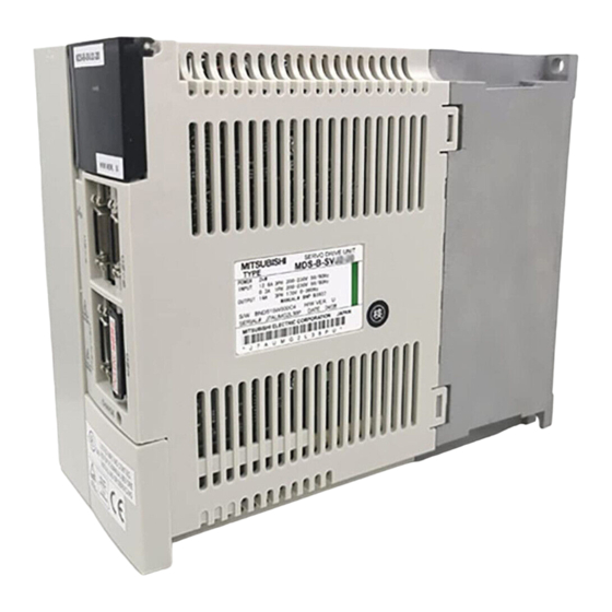
0.3A 1PH 200-230V 50/60Hz Rated output OUTPUT 3.6A 3PH 170V 0-360Hz MANUAL# BNP-B3937 Software, hardware version S/W BND515W000C3 H/W VER. L SERIAL# XXXXXXXXXXX DATE 00/01 Serial No., Data of manufacture MITSUBISHI ELECTRIC CORPORATION JAPAN X X X X X X X X X... - Page 41 SERVO MOTOR ASSY • Medium inertia HC102S-A42 TYPE Type • For CNC feed shaft SER. XXXXXXXXXXXX/ DATE 9910 Serial No. MITSUBISHI ELECTRIC CORPORATION JAPAN Rating nameplate MITSUBISHI AC SERVO MOTOR Motor type HC102S Detector INPUT 3AC 123V 6.0A Rated output...
- Page 42 HA80NBS-A42 MOTOR 1kW 2000r/min Rated output ENCODER ABS 100000p/rev Detector Serial No., SERIAL# DATE 9706 XXXXXXXXXXX Data of manufacture MITSUBISHI ELECTRIC CORPORATION JAPAN ① N ② ③ ④ − ⑤ ⑤ Detector Detection Detector Detector Symbol method resolution type 25000p/rev...
- Page 43 INPUT 3AC 126V 3.2A Rated output OUTPUT 0.5kW IEC34-1 1994 Detector 2000r/min IP65 CI.F 5.0kg SER.No.XXXXXXXXX DATE 98-9 Serial No., MITSUBISHI ELECTRIC MADE IN JAPAN Data of manufacture HC−SF ② ③ ④ ④Shaft end shape HC-RF Series The taper shaft...
- Page 44 INPUT 3AC 129V 3.6A machines OUTPUT 600W IEC34-1 1994 Rated output SPEED 3000r/min Detector SER.No.XXXXXXXXX DATE 98-9 Serial No., MITSUBISHI ELECTRIC MADE IN JAPAN Data of manufacture HA−FF ② ③ ④ ⑤ ⑥ ⑥ Standards and environment compliance HC-MF Series Standards and Symbol •...
-
Page 45: Explanation Of Each Part
Chapter 1 Preface 1-2 Explanation of each part 1-2-1 Explanation of each servo amplifier part Absolute position detection battery Absolute position detection battery holder Absolute position detection battery connector Display section : The operation status and alarms are displayed. Axis No. setting rotary switch Installation screw hole Display setting section cover CN1A... -
Page 47: Chapter 2 Wiring And Connection
Chapter 2 Wiring and Connection 2-1 System connection diagram ......................2-3 2-2 Servo amplifier main circuit terminal block, control circuit terminal block ........2-4 2-2-1 Main circuit terminal block, control circuit terminal block signal layout ........2-4 2-2-2 Names and application of main circuit terminal block and control circuit terminal block signals ................... - Page 48 Chapter 2 Wiring and Connection 1. Wiring work must be done by a qualified technician. 2. Wait at least 10 minutes after turning the power OFF and check the voltage with a tester, etc., before starting wiring. Failure to observe this could lead to electric shocks.
-
Page 49: System Connection Diagram
Chapter 2 Wiring and Connection 2-1 System connection diagram Configure a sequence that shuts off the MC when an emergency stop occurs. The converter unit output or CN3 connector Servo amplifier M D S - B - S V J 2 output (MC) of the SVJ2 amplifier can be used. -
Page 50: Servo Amplifier Main Circuit Terminal Block, Control Circuit Terminal Block
Chapter 2 Wiring and Connection 2-2 Servo amplifier main circuit terminal block, control circuit terminal block Do not apply a voltage other than that specified in Instruction Manual on each CAUTION terminal. Failure to observe this item could lead to ruptures or damage, etc. 2-2-1 Main circuit terminal block, control circuit terminal block signal layout The signal layout of each terminal block is as shown below. -
Page 51: Names And Application Of Main Circuit Terminal Block And Control Circuit Terminal
Chapter 2 Wiring and Connection 2-2-2 Names and application of main circuit terminal block and control circuit terminal block signals The following table shows the details for each terminal block signal. Name Signal name Description Main circuit power supply input terminal Main circuit L1·L2·L3 power supply... -
Page 52: How To Use The Control Circuit Terminal Block (Mds-B-Svj2-01~07)
Chapter 2 Wiring and Connection 2-2-3 How to use the control circuit terminal block (MDS-B-SVJ2-01~07) (1) For connector of the spring lock type • Treatment of wire end (a) Single strand Peel the wire sheath, and use the wire. Sheeth Core Approx. - Page 53 Chapter 2 Wiring and Connection • Connection method (a) When the wire is inserted directly Insert the wire to the end pressing the button with a small flat-blade screwdriver or the like. Button Small flat blade screwdriver or the like When removing the short-circuit bar from across P-D, press the buttons of P and D alternately pulling the...
- Page 54 Chapter 2 Wiring and Connection (2) For connector of the screw lock type • Treatment of wire end (a) Single strand Peel the wire sheath, and use the wire. Sheeth Core Approx. 10mm (b) Stranded wire Peel the wire sheath, and then twist the core wires. Take care to prevent short circuits with the neighboring poles due to the fine strands of the core wires.
-
Page 55: Nc And Servo Amplifier Connection
Chapter 2 Wiring and Connection 2-3 NC and servo amplifier connection The NC bus cables are connected from the NC to each servo amplifier so that they run in a straight line from the NC to the terminator connector (battery unit). MDS-C1-V1/V2 Series servo amplifiers and spindle amplifiers can be connected in combination, and up to 7 axes can be connected per system. -
Page 56: Motor And Detector Connection
Chapter 2 Wiring and Connection 2-4 Motor and detector connection 2-4-1 Connection of HC52, HC53, HC102* (1) HC52/HC53/HC102 -A47 The OSA17 detector is used, and the wiring differs from the other HC motor detectors. HC102* is connected with an amplifier having a one-rank lower capacity. MDS-B-SVJ2-06 to 07 Detector connector Detector connector: CN2... -
Page 57: Connection Of Hc102, Hc103, Hc152*, Hc152, Hc153
Chapter 2 Wiring and Connection 2-4-2 Connection of HC102, HC103, HC152*, HC152, HC153 (1) HC102/HC103/HC152/HC153 -A47 The OSA17 detector is used, and the wiring differs from the other HC motor detectors. HC152* is connected with an amplifier having a one-rank lower capacity. Detector connector Detector connector: CN2 MDS-B-SVJ2-10 to 20... -
Page 58: Connection Of Hc202*, Hc202, Hc203*, Hc352
Chapter 2 Wiring and Connection 2-4-3 Connection of HC202*, HC202, HC203*, HC352* (1) HC202/HC203/HC352 -A47 The OSA17 detector is used, and the wiring differs from the other HC motor detectors. HC202* is connected with an amplifier having a one-rank lower capacity. MDS-B-SVJ2-10 to 20 Detector connector Detector connector: CN2... -
Page 59: Connection Of Hc103R, Hc153R, Hc203R
Chapter 2 Wiring and Connection 2-4-4 Connection of HC103R, HC153R, HC203R (1) HC103R/HC153R/HC203R -A47 The OSA17 detector is used, and the wiring differs from the other HC motor detectors. Detector connector MDS-B-SVJ2-10 to 20 Detector connector: CN2 MS3102A20-29P Pin No. No.1 No.11 Option cable: CNV2C... -
Page 60: Connection Of Ha053N, Ha13N
Chapter 2 Wiring and Connection 2-4-5 Connection of HA053N, HA13N Either the OSE253, OSA253, OSE104 or OSA104 detector can be used. The connection methods are the same for all types. MDS-B-SVJ2-01 Detector connector Detector connector: CN2 MS3102A22-14P Pin No. No.1 No.11 No.10 No.20... -
Page 61: Connection Of Ha40N,Ha43N
Chapter 2 Wiring and Connection 2-4-7 Connection of HA40N,HA43N Either the OSE253, OSA253, OSE104 or OSA104 detector can be used. The connection methods are the same for all types. MDS-B-SVJ2-06 Detector connector: CN2 Detector connector MS3102A22-14P Pin No. No.1 No.11 No.10 No.20 Option cable: CNV12... -
Page 62: Connection Of Ha100N, Ha103N*, Ha200N
Chapter 2 Wiring and Connection 2-4-9 Connection of HA100N, HA103N*, HA200N* Either the OSE253, OSA253 OSE104 or OSA104 detector can be used. The connection methods are the same for all types. HA103N* and HA200N* are connected with an amplifier having a one-rank lower capacity than the standard detector. -
Page 63: Connection Of Hc-Sf52, Hc-Sf53, Hc-Sf102, Hc-Sf103
Chapter 2 Wiring and Connection 2-4-10 Connection of HC-SF52, HC-SF53, HC-SF102, HC-SF103 MDS-B-SVJ2-06 to 07 Detector connector Detector connector: CN2 MS3102A20-29P Pin No. No.1 No.11 No.10 No.20 Option cable: CNV2C (Refer to Chapter 6 for details on the cable treatment) Signal Signal Max. -
Page 64: Connection Of Hc-Sf202, Hc-Sf203, Hc-Sf352, Hc-Sf353
Chapter 2 Wiring and Connection 2-4-12 Connection of HC-SF202, HC-SF203, HC-SF352, HC-SF353 MDS-B-SVJ2-10 to 20 Detector connector Detector connector: CN2 MS3102A20-29P Pin No. No.1 No.11 No.10 No.20 Option cable: CNV2C (Refer to Chapter 6 for details on the cable treatment) Signal Signal Max. -
Page 65: Connection Of Ha-Ff Series
Chapter 2 Wiring and Connection 2-4-14 Connection of HA-FF Series MDS-B-SVJ2-01 to 06 Detector connector: CN2 Detector connector Pin No. No.1 No.11 No.10 No.20 Option cable: MR-JHSCBL□M-H (Refer to Chapter 6 for details on the Signal Signal Signal cable treatment) Max. -
Page 66: Connection Of Hc-Mf(-Ue) Series
Chapter 2 Wiring and Connection 2-4-16 Connection of HC-MF(-UE) Series MDS-B-SVJ2-01 to 04 Detector connector Detector connector: CN2 MDS-B-SVJ2-07 172161-9 Pin No. No.1 No.11 No.10 No.20 Option cable: MR-JHSCBL□M-H (Refer to Chapter 6 for details on the Signal cable treatment) Signal Signal Max. -
Page 67: Connection Of Power Supply
Chapter 2 Wiring and Connection 2-5 Connection of power supply 1. Make sure that the power supply voltage is within the specified range of the servo amplifier. Failure to observe this could lead to damage or faults. 2. For safety purposes, always install a circuit protector, and make sure that the circuit is cut off when an error occurs or during inspections. - Page 68 Chapter 2 Wiring and Connection (2) When not sharing a converter and power supply If the rated current exceeds 60A by the selection of the circuit protector when the converter and power supply are shared, install the circuit protectors and contactors separate from the converter unit.
-
Page 69: Example Of Connection When Controlling The Contactor With The Mds-B-Svj2
Chapter 2 Wiring and Connection 2-5-2 Example of connection when controlling the contactor with the MDS-B-SVJ2 Drive the contactor via the relay from the contactor control output (MC) of the CN3 connector. There are also some types of contactors that can be directly driven with 24VDC. Circuit 3-phase protector... -
Page 70: Connection Of Regenerative Resistor
Chapter 2 Wiring and Connection 2-6 Connection of regenerative resistor The servo amplifier has an internal regenerative resistor electronic thermal (software process), and when overheating of the regenerative resistor is detected, an over-regeneration (alarm 30) is detected. The parameters must be set correctly for the electronic thermal to operate correctly. Refer to section "6-1-1 Combinations with servo amplifiers"... -
Page 71: Connection Of External Option Regenerative Resistor
Chapter 2 Wiring and Connection 2-6-2 Connection of external option regenerative resistor Remove the short bar connected between terminals P and D, and connect the regenerative resistor between terminals P and C. External option regenerative resistor SVJ2 terminal block Use a flame retardant twisted wire. Wiring length 5m or less 100mm or more 100mm or more... -
Page 72: Connection Of External Option Regeneration Resistance Unit
Chapter 2 Wiring and Connection 2-6-3 Connection of external option regeneration resistance unit Disconnect the short bar connected between the P and D terminals, and connect the option regeneration resistor between the P and C terminals. The thermal protector terminals (G3, G4) are used together with the electronic thermal to provide double-protection against overheating of the regenerative resistor. -
Page 73: Wiring Of Contactors
Chapter 2 Wiring and Connection 2-7 Wiring of contactors A contactor (magnetic contactor) is inserted in the main circuit power supply input (L1, L2, L3) of servo amplifier, and the power supply input is shut off when an emergency stop or servo alarm occurs. When an emergency stop or servo alarm occurs, the servo amplifier stops the motor using deceleration control or a dynamic brake. -
Page 74: Contactor Power On Sequences
Chapter 2 Wiring and Connection 2-7-1 Contactor power ON sequences The main circuit power supply is turned ON in the sequences in the following drawing when the contactor control output (CN3 connector: MC) of the MDS-B-SVJ2 servo amplifier is used. In the 200msec interval after the amplifier emergency stop input is canceled, the contactor contact fusion is checked by discharging the PN bus voltage with the regenerative resistor. -
Page 75: Contactor Control Signal (Mc) Output Circuit
Chapter 2 Wiring and Connection 2-7-3 Contactor control signal (MC) output circuit A relay or photo coupler can be driven. When using an inductive load, install a diode. (Tolerable current: 40mA or less, rush current: 100mA or less) Contactor The servo amplifier will MDS-B-SVJ2 fail if the diode polarity is incorrect. -
Page 76: Wiring Of Motor Brake
Chapter 2 Wiring and Connection 2-8 Wiring of motor brake The magnetic brake of servomotors with magnetic brake is driven by the control signal (MBR) output by the servo amplifier MDS-B-SVJ2. The servo amplifier releases the brake when the motor is ON. (Servo ON means when torque is generated in the motor.) Parameter setting is not required when using motor brake control output (MBR). -
Page 77: Motor Brake Control Signal (Mbr) Output Circuit
Chapter 2 Wiring and Connection 2-8-4 Motor brake control signal (MBR) output circuit The motor brake power supply is controlled via a relay. When using an inductive load, install a diode. (Tolerable current: 40mA or less, rush current: 100mA or less) The servo amplifier will MDS-B-SVJ2 fail if the diode polarity... -
Page 78: Wiring Of External Emergency Stop
Chapter 2 Wiring and Connection 2-9 Wiring of external emergency stop 2-9-1 External emergency stop setting Besides the main emergency stop input from the CNC bus line (CN1A, CN1B), double-protection when an emergency stop occurs is possible by directly inputting an independent external emergency stop to the servo amplifier. -
Page 79: External Emergency Stop Operation Sequences
Chapter 2 Wiring and Connection 2-9-2 External emergency stop operation sequences If only an external emergency stop is input when external emergency stop valid is set in the parameters (the main emergency stop is not input), an "In external emergency stop" (warning EA) will be detected. -
Page 80: External Emergency Stop Signal (Emgx) Input Circuit
Chapter 2 Wiring and Connection 2-9-3 External emergency stop signal (EMGX) input circuit Issue a signal with a relay or open collector transistor. When using an external power supply, the power supply for the contactor control output and motor brake control output is the same external power supply. - Page 81 Chapter 3 Installation 3-1 Installation of servo amplifier ......................3-2 3-1-1 Environmental conditions ......................3-2 3-1-2 Installation direction and clearance ................... 3-3 3-1-3 Prevention of entering of foreign matter ..................3-3 3-2 Installation of servomotor ......................... 3-4 3-2-1 Environmental conditions ......................3-4 3-2-2 Cautions for mounting load (prevention of impact on shaft)............
-
Page 82: Chapter 3 Installation
Chapter 3 Installation 1. Install the unit on noncombustible material. Direct installation on combustible material or near combustible materials could lead to fires. 2. Follow this Instruction Manual and install the unit in a place where the weight can be borne. 3. -
Page 83: Installation Direction And Clearance
Chapter 3 Installation 3-1-2 Installation direction and clearance Install the servo amplifier so that the front side is visible. Refer to the following drawings for the heat dissipation and wiring of each unit, and secure sufficient space for ventilation. Front view Side view (Top) 100mm... -
Page 84: Installation Of Servomotor
Chapter 3 Installation 3-2 Installation of servomotor 1. Do not hold the cables, axis or detector when transporting the servomotor. Failure to observe this could lead to faults or injuries. 2. Securely fix the servomotor to the machine. Insufficient fixing could lead to the servomotor deviating during operation. -
Page 85: Cautions For Mounting Load (Prevention Of Impact On Shaft)
Chapter 3 Installation 3-2-2 Cautions for mounting load (prevention of impact on shaft) ① When using the servomotor with key way, use the screw hole Double-end stud at the end of the shaft to mount the pulley onto the shaft. To Servom otor install, first place the double-end stud into the shaft screw holes, contact the coupling end surface against the washer,... -
Page 86: Tolerable Load Of Axis
Chapter 3 Installation 3-2-4 Tolerable load of axis There is a limit to the load that can be applied on the motor shaft. Make sure that the load applied on the radial direction and thrust direction, when mounted on the machine, is below the tolerable values given below. -
Page 87: Oil And Waterproofing Measures
Chapter 3 Installation 3-2-5 Oil and waterproofing measures ① A format based on IEC Standards (IP types) is displayed as the Oil or water servomotor protective format (refer to "10-2-1 List of Specifications."). However, these Standards are short-term performance specifications. They do not guarantee continuous environmental protection characteristics. - Page 88 Chapter 3 Installation ④ Do not use the unit with the cable submerged in oil or water. (Refer to right drawing.) Cover Servomotor Oil or water pool <Fault> Capillary tube phenomenon ⑤ Make sure that oil and water do not flow along the cable into the motor or detector.
-
Page 89: Cable Stress
Chapter 3 Installation 3-2-6 Cable stress 1. Sufficiently consider the cable clamping method so that bending stress and the stress from the cable's own weight is not applied on the cable connection. Failure to observe this could lead to damage of the cable sheath and electric shocks. -
Page 90: Noise Measures
Chapter 3 Installation 3-3 Noise measures Noise includes that which enters the servo amplifier from an external source and causes the servo amplifier to malfunction, and that which is radiated from the servo amplifier or motor and causes the peripheral devices or amplifier itself to malfunction. The servo amplifier output is a source of noise as the DC voltage is switched at a high frequency. - Page 91 Chapter 3 Installation ⑤ ⑦ ② ⑦ ② ① Sensor Servo power Instru- Receiver amplifier supply ment ⑥ ③ ④ ⑧ Sensor SM Servomotor Noise propaga- Measures tion path When devices such as instruments, receivers or sensors, which handle minute signals and are easily affected by noise, or the signal wire of these devices, are stored in the same panel as the servo amplifier and the wiring is close, the device could malfunction due to airborne propagation of the noise.
-
Page 93: Chapter 4 Setup
Chapter 4 Setup 4-1 Initial setup of servo amplifier ......................4-2 4-1-1 Setting the rotary switches ......................4-2 4-1-2 Transition of LED display after power is turned ON ..............4-2 4-2 Setting the initial parameters ......................4-3 4-2-1 Servo specification parameters ....................4-3 4-2-2 Limitations to electronic gear setting value ................ -
Page 94: Initial Setup Of Servo Amplifier
Chapter 4 Setup 4-1 Initial setup of servo amplifier 4-1-1 Setting the rotary switches Before turning on the power, the axis No. must be set with the rotary switches. The rotary switch settings will be validated when the amplifier power is turned ON. Rotary switch setting Set axis No. -
Page 95: Setting The Initial Parameters
Chapter 4 Setup 4-2 Setting the initial parameters The servo parameters must be set to start up the servo drive system. The servo parameters are input from the CNC. The input method will differ according to the CNC, so refer to the Instruction Manual provided with each CNC. 4-2-1 Servo specification parameters The servo specification parameters are determined according to the machine specifications and servo system specifications. -
Page 96: Limitations To Electronic Gear Setting Value
Chapter 4 Setup 4-2-2 Limitations to electronic gear setting value The servo amplifier has internal electronic gears. The command value from the NC is converted into a detector resolution unit to carry out position control. The electronic gears are single gear ratios calculated from multiple parameters as shown below. - Page 97 Chapter 4 Setup Motor single unit HC352* <HC > <HC R> HC202* HC203* Standard HC103R VGN1 HC153R HC202 HC203R HC53 HC103 HC52 HC153 HC102 HC102* HC152 HC152* Load inertia scale Load inertia scale (total load inertia/motor inertia) (total load inertia/motor inertia) HA200N* <HA N>...
-
Page 98: Standard Parameter List According To Motor
Chapter 4 Setup 4-3 Standard parameter list according to motor Set the standard parameters for parameters not explained in section "4-2 Setting the initial parameters". (1) HC Series (2000r/min. rating) Motor series name HC -E42, -E33, HC -A47, -A42, -A33 HC -E42, -E33 : INC, HC -A47, -A42, -A33 : ABS ABS/INC (HC -A47 can also be used with the INC system) - Page 99 Chapter 4 Setup (2) HC Series (3000r/min. rating) Motor series name HC -E42, -E33, HC -A47, -A42, -A33 HC -E42, -E33 : INC, HC -A47, -A42, -A33 : ABS ABS/INC (HC -A47 can also be used with the INC system) Motor capacity symbol Connected amplifier type (MDS-B-) SVJ2-06...
- Page 100 Chapter 4 Setup (3) HC R Series Motor series name HC R-E42, -E33, HC R-A47, -A42, -A33 HC R-E42, -E33 : INC, HC R-A47, -A42, -A33 : ABS ABS/INC (HC R-A47 can also be used with the INC system) Motor capacity symbol Connected amplifier type (MDS-B-) SVJ2-10 SVJ2-10 (Caution)
- Page 101 Chapter 4 Setup (4) HA N Series (2000r/min rating) Motor series name HA -E42, -E33, HA -A42, -A33 ABS/INC HA -E42, -E33 : INC, HA -A42, -A33 : ABS Motor capacity symbol 100N 200N Connected amplifier type (MDS-B-) SVJ2-06 SVJ2-10 SVJ2-20 SVJ2-20 Abbrev.
- Page 102 Chapter 4 Setup (5) HA N Series (3000r/min rating) Motor series name HA -E42, -E33, HA -A42, -A33 ABS/INC HA -E42, -E33 : INC, HA -A42, -A33 : ABS Motor capacity symbol 053N 103N Connected amplifier type (MDS-B-) SVJ2-01 SVJ2-03 SVJ2-06 SVJ2-10 SVJ2-20 Abbrev.
- Page 103 Chapter 4 Setup (6) HC-SF Series (2000r/min rating) Motor series name HC-SF ABS/INC This is only for ABS specifications. This can be used with the INC system. Motor capacity symbol Connected amplifier type (MDS-B-) SVJ2-07 SVJ2-10 SVJ2-10 SVJ2-20 SVJ2-06 (Caution) (Caution) (Caution) (Caution)
- Page 104 Chapter 4 Setup (7) HC-SF Series (3000r/min rating) Motor series name HC-SF ABS/INC This is only for ABS specifications. This can be used with the INC system. Motor capacity symbol Connected amplifier type (MDS-B-) SVJ2-07 SVJ2-10 SVJ2-10 SVJ2-20 SVJ2-06 (Caution) (Caution) (Caution) (Caution)
- Page 105 Chapter 4 Setup (8) HC-RF Series Motor series name HC-RF ABS/INC This is only for ABS specifications. This can be used with the INC system. Motor capacity symbol Connected amplifier type (MDS-B-) SVJ2-10 SVJ2-10 (Caution) SVJ2-20 Abbrev. Parameter name SV001 Motor side gear ratio Set the motor side gear ratio in PC1 and the machine side gear ratio in PC2.
- Page 106 Chapter 4 Setup HA-FF Series Motor series name HC-FF ABS/INC This is only for ABS specifications. This can be used with the INC system. Motor capacity symbol Connected amplifier type (MDS-B-) SVJ2-01 SVJ2-01 SVJ2-03 SVJ2-03 SVJ2-04 SVJ2-06 Abbrev. Parameter name SV001 Motor side gear ratio Set the motor side gear ratio in PC1 and the machine side gear ratio in...
- Page 107 Chapter 4 Setup (10) HC-MF Series Motor series name HC-MF ABS/INC This is only for ABS specifications. This can be used with the INC system. Motor capacity symbol Connected amplifier type (MDS-B-) SVJ2-01 SVJ2-01 SVJ2-03 SVJ2-04 SVJ2-07 Abbrev. Parameter name SV001 Motor side gear ratio Set the motor side gear ratio in PC1 and the machine side gear ratio in...
-
Page 109: Chapter 5 Adjustment
Chapter 5 Adjustment 5-1 Measurement of adjustment data..................... 5-2 5-1-1 D/A output specifications ......................5-2 5-1-2 Setting the output data....................... 5-2 5-1-3 Setting the output scale ......................5-3 5-1-4 Setting the offset amount......................5-3 5-1-5 Clamp function........................... 5-3 5-1-6 Filter function ..........................5-3 5-2 Gain adjustment .......................... -
Page 110: Measurement Of Adjustment Data
Chapter 5 Adjustment 5-1 Measurement of adjustment data The MDS-B-SVJ2 servo amplifier has a function to D/A output the various control data. To adjust the servo and set the servo parameters that match the machine, it is necessary to use the D/A output and measure the internal status of the servo. -
Page 111: Setting The Output Scale
Chapter 5 Adjustment 5-1-3 Setting the output scale This is set when an output is to made with a unit other than the standard output unit. (Example 1) When SV061= 5, SV063 = 2560 The V-phase current value will be output with 1A/V unit to D/A output ch. 1. (Example 2) When SV063 = 11, SV064 = 128 The position droop will be output with a 2mm/V unit to the D/A output ch. -
Page 112: Gain Adjustment
Chapter 5 Adjustment 5-2 Gain adjustment 5-2-1 Current loop gain Abbrev. Parameter name Explanation Setting range This setting is determined by the motor's electrical SV009 Current loop q axis lead 1 ~ 20480 characteristics. compensation Set the standard parameters for all parameters. SV010 Current loop d axis lead 1 ~ 20480... - Page 113 Chapter 5 Adjustment (2) Setting the speed loop lead compensation The speed loop lead compensation (SV008: VIA) determines the characteristics of the speed loop mainly at low frequency regions. 1364 is set as a standard, and 1900 is set as a standard during SHG control.
-
Page 114: Position Loop Gain
Chapter 5 Adjustment 5-2-3 Position loop gain (1) Setting the position loop gain The position loop gain (SV003:PGN1) is a parameter that determines the trackability to the command position. 33 is set as a standard. Set the same position loop gain value between interpolation axes. - Page 115 Chapter 5 Adjustment (3) SHG control (option function) If the position loop gain is increased or feed forward control (CNC function ) is used to shorten the settling time or increase the precision, the machine system may vibrate easily. SHG control changes the position loop to a high-gain by stably compensating the servo system position loop through a delay.
-
Page 116: Characteristics Improvement
Chapter 5 Adjustment 5-3 Characteristics improvement 5-3-1 Optimal adjustment of cycle time The following items must be adjusted to adjust the cycle time. Refer to the Instruction Manuals provided with each CNC for the acceleration/deceleration pattern. ①Rapid traverse rate (rapid) : This will affect the maximum speed during positioning. - Page 117 Chapter 5 Adjustment (2) Adjusting the cutting rate To adjust the cutting rate, the CNC axis specification parameter clamp speed (clamp) and acceleration/deceleration time constant (G1t ) are adjusted. The in-position width at this time must be set to the same value as actual cutting. •...
- Page 118 Chapter 5 Adjustment (4) Adjusting the settling time The settling time is the time required for the position droop to enter the in-position width after the feed command (F⊿T) from the CNC reaches 0. Setting time F⊿T The settling time can be shortened by raising the position loop gain or using Time control.
-
Page 119: Vibration Suppression Measures
Chapter 5 Adjustment 5-3-2 Vibration suppression measures If vibration (machine resonance) occurs, it can be suppressed by lowering the speed loop gain (VGN1). However, cutting precision and cycle time will be sacrificed. (Refer to "5-2-2 Speed loop gain".) Thus, try to maintain the VGN1 as high as possible, and suppress the vibration using the vibration suppression functions. - Page 120 Chapter 5 Adjustment (2) Notch filter 2 The frequency can be set separately from the notch filter 1. Note that low frequencies cannot be set and the depth cannot be compensated. Abbrev. Parameter name Explanation SV033 SSF2 Servo function selection 2 The notch filter 2 sets the operation frequency with the following parameters.
- Page 121 Chapter 5 Adjustment (4) Adaptive filter (option function) The servo amplifier detects the machine resonance point and automatically sets the filter constant. Even if the ball screw and table position relation changes causing the resonance point to change, the filter will track these changes. Set the servo function selection 1 (SV027: SSF1) bit F to activate the adaptive filter.
-
Page 122: Improving The Cutting Surface Precision
Chapter 5 Adjustment 5-3-3 Improving the cutting surface precision If the cutting surface precision is poor, it can be improved by adjusting the speed loop gain or by using the voltage dead zone compensation or disturbance observer function. <Examples of faults> •... - Page 123 Chapter 5 Adjustment (4) Disturbance observer The disturbance observer can reduce the effect caused by disturbance, frictional resistance or torsion vibration during cutting by estimating the disturbance torque and compensating it. It also is effective in suppressing the vibration caused by speed leading compensation control. <Setting method>...
-
Page 124: Improvement Of Protrusion At Quadrant Changeover
Chapter 5 Adjustment 5-3-4 Improvement of protrusion at quadrant changeover The response delay (caused by non-sensitive band from friction, torsion, expansion/contraction, backlash, etc.) caused when the machine advance direction reverses is compensated with the lost motion compensation (LMC compensation) function. With this, the protrusions that occur with the quadrant changeover in the DDB measurement method, or the streaks that occur when the quadrant changes during circular cutting can be improved. - Page 125 Chapter 5 Adjustment <Adjustment method> First confirm whether the axis to be compensated is an unbalance axis (vertical axis, slant axis). If it is an unbalance axis, carry out the adjustment after performing step "(2) Unbalance torque compensation". Next, measure the frictional torque. Carry out reciprocation operation (approx. F1000) with the axis to be compensated and measure the load current % when fed at a constant speed on the CNC servo monitor screen.
- Page 126 Chapter 5 Adjustment (2) Unbalance torque compensation If the load torque differs in the positive and negative directions such as with a vertical axis or slant axis, the torque offset (SV032:TOF) is set to carry out accurate lost motion compensation. <Setting method>...
- Page 127 Chapter 5 Adjustment (3) Adjusting the lost motion compensation timing If the speed loop gain has been lowered from the standard setting value because the machine rigidity is low or because machine resonance occurs easily, or when cutting at high speeds, the quadrant protrusion may appear later than the quadrant changeover point on the servo control.
- Page 128 Chapter 5 Adjustment (4) Adjusting for feed forward control In LMC compensation, a model position considering the position loop gain is calculated based on the position command sent from the CNC, and compensation is carried out when the feed changes to that direction. When the CNC carries out feed forward (fwd) control, overshooting equivalent to the operation fraction unit occurs in the position commands, and the timing of the model position direction change may be mistaken.
-
Page 129: Improvement Of Overshooting
Chapter 5 Adjustment 5-3-5 Improvement of overshooting The phenomenon when the machine position goes past or exceeds the command during feed stopping is called overshooting. Overshooting is compensated by overshooting compensation (OVS compensation). The phenomenon when the machine position exceeds the command during feed stopping is called overshooting. - Page 130 Chapter 5 Adjustment (2) Adjusting for feed forward control Use OVS compensation type 2 if overshooting is a problem in contour cutting during feed forward control. If OVS compensation type 2 is used to attempt to compensate overshooting, the overshooting may conversely become larger, or projections may appear during arc cutting.
-
Page 131: Improvement Of Characteristics During Acceleration/Deceleration
Chapter 5 Adjustment 5-3-6 Improvement of characteristics during acceleration/deceleration (1) SHG control (option function) Because SHG control has a smoother response than conventional position controls, the acceleration/deceleration torque (current FB) has more ideal output characteristics (A constant torque is output during acceleration/deceleration.) The peak torque is kept low by the same acceleration/deceleration time constant, enabling the time constant to be shortened. - Page 132 Chapter 5 Adjustment (2) Acceleration feed forward Vibration may occur at 10 to 20 Hz during acceleration/deceleration when a short time constant of 30 msec or less is applied, and a position loop gain (PGN1) higher than the general standard value or SHG control is used.
- Page 133 Chapter 5 Adjustment (3) Inductive voltage compensation The current loop response is improved by compensating the back electromotive force element induced by the motor rotation. This improved the current command efficiency, and allows the acceleration/deceleration time constant to the shortened. <Adjustment method>...
-
Page 134: Setting For Emergency Stop
Chapter 5 Adjustment 5-4 Setting for emergency stop The emergency stop referred to here indicates the following states. ① When the external emergency stop was input (including other axis alarms) ② When the CNC power down was detected ③ When a servo alarm was detected 5-4-1 Deceleration control This MDS-B-SVJ2 servo amplifier decelerates the motor according to the set time constant in the ready ON state even when an emergency stop occurs, and activates the dynamic brakes after... - Page 135 Chapter 5 Adjustment If the deceleration time constant at emergency stop (EMGt) is set longer than the acceleration/deceleration time constant, the overtravel point (stroke end CAUTION point) may be exceeded. A collision may be caused on the machine end, so be careful. (2) Dynamic brake stop When an emergency stop occurs, it is possible to have the machine stop from the beginning using a dynamic brake without controlling the deceleration.
-
Page 136: Vertical Axis Drop Prevention Control
Chapter 5 Adjustment 5-4-2 Vertical axis drop prevention control (1) Vertical axis drop prevention control The vertical axis drop prevention control is a function that prevents the vertical axis from dropping due to a delay in the brake operation when an emergency stop occurs. The servo ready OFF will be delayed by the time set in the parameter from when the emergency stop occurs. - Page 137 Chapter 5 Adjustment (2) Vertical axis lift up control Even when the vertical axis drop prevention control is applied, the axis will drop several µm due to the mechanical play of the motor brakes. This function raises the axis, before the brakes are applied, by a motor angle of 1.44deg.
-
Page 138: Collision Detection
Chapter 5 Adjustment 5-5 Collision detection The purpose of the collision detection function is to quickly detect a collision and decelerate to a stop. This suppresses the excessive torque generated to the machine tool, and suppresses the occurrence of an abnormality. Impact during a collision cannot be prevented even when the collision detection function is used, so this function does not guarantee that the machine will not break and does not guarantee the machine accuracy after a collision. - Page 139 Chapter 5 Adjustment <Setting and adjustment methods> 1. Confirm that SHG control is being used. The collision detection function is valid only during SHG control. 2. Measure the unbalance torque, and set in the torque offset (SV32: TOF). Refer to the section "5-3-4 (2) Unbalance torque compensation"...
- Page 140 Chapter 5 Adjustment Abbrev. Parameter name Explanation SV034 SSF3 Servo function selection 3 The display for the load inertia rate and collision detection related data is set with the following parameters. daf2 daf1 dac2 dac1 MAX current 1 MAX current 2 0 Max.
-
Page 141: Parameter List
Chapter 5 Adjustment 5-6 Parameter list Setting range Abbrev. Parameter name Explanation (Unit) Motor side gear Set the motor side and machine side gear ratio. SV001 PC1* 1 to 32767 ratio For the rotary axis, set the total deceleration (acceleration) ratio. Even if the gear ratio is within the setting range, the electronic gears may Machine side gear SV002... - Page 142 Chapter 5 Adjustment Setting range Abbrev. Parameter name Explanation (Unit) Set this when the protrusion (that occurs due to the non-sensitive band by friction, torsion, backlash, etc) at quadrant change is too large. This compensates the torque at quadrant change. This is valid only when the lost motion compensation (SV027 (SSF1/lmc)) is selected.
- Page 143 Chapter 5 Adjustment Setting range Abbrev. Parameter name Explanation (Unit) For both parameters, set the number of pulses per one revolution of the motor detector. Position detector Setting value SV019 RNG1* Motor model name resolution SV019 SV020 HC*-E42/A42/A47, HC*R-E42/A42/A47 8 to 100 HA*N-E42/A42 (kp/rev) HC*-E33/A33, HC*R-E33/A33...
- Page 144 Chapter 5 Adjustment Abbrev. Parameter name Explanation mtyp Explanation Set the motor type. Setting HA40N HA-FF43 HA43N HA80N HA-FF63 HA83N mtyp HA100N HA103N HA200N HA93N HA-FF053 HA053N HA-FF13 HA13N HA-FF23 HA23N HA-FF33 HA33N Setting HC-MF4 HC52 or HC53 or HC-SF52 HC-SF53 HC-MF7 HC102 or...
- Page 145 Chapter 5 Adjustment Setting range Abbrev. Parameter name Explanation (Unit) Excessive error Set the excessive error detection width when servo ON. 0 to 32767 SV026 detection width For the standard setting, refer to the explanation of SV023 (OD1). (mm) during servo OFF When “0”...
- Page 146 Chapter 5 Adjustment Setting range Abbrev. Parameter name Explanation (Unit) Set this if overshooting occurs during positioning. This compensates the motor torque during positioning. This is valid only when the overshooting compensation SV027 (SSF1/ovs) is selected. Type 1: When SV027 (SSF1)/ bit11, 10 (ovs)=01 Set the compensation amount based on the motor’s stall (rated) current.
- Page 147 Chapter 5 Adjustment Abbrev. Parameter name Explanation daf2 daf1 dac2 dac1 Meaning when “0” is set Meaning when “1” is set NC servo monitor MAX current display data changeover Setting MAX current 1 MAX current 2 Max. current command value Max.
- Page 148 Chapter 5 Adjustment Explanation Abbrev. Parameter name cl2n clG1 Meaning when “0” is set Meaning when “1” is set Servo function SV035 SSF4 selection 4 Collision detection method 1 Set the collision detection level during cutting feed (G1). 13 clG1 The G1 collision detection level=SV060*clG1. When clG1=0, the collision detection method 1 during cutting feed won’t function.
- Page 149 Chapter 5 Adjustment Explanation Abbrev. Parameter name rtyp emgx Explanation Always set to “0(0000)”. Set the external emergency stop function. (Setting is prohibited for values with no description.) 5 emgx Setting Explanation External emergency stop invalid External emergency stop valid Regenerative SV036 PTYP*...
- Page 150 Chapter 5 Adjustment Setting range Abbrev. Parameter name Explanation (Unit) Set “the motor inertia + motor axis conversion load inertia” in respect to the motor inertia. 0 to 5000 SV037 Load inertia scale Jl+Jm Jm: Motor inertia SV037 (JL) = *100 Jl: Motor axis conversion load inertia...
- Page 151 Chapter 5 Adjustment Setting range Abbrev. Parameter name Explanation (Unit) Set the time constant used for the deceleration control at emergency stop. Deceleration time Set a length of time that takes from rapid traverse rate (rapid) to stopping. 0 to 5000 SV056 EMGt constant at...
- Page 153 Chapter 6 Dedicated Options 6-1 Regenerative option ......................... 6-3 6-1-1 Combinations with servo amplifiers ................... 6-3 6-1-2 Outline dimension drawing of external option regenerative resistor ......... 6-4 6-1-3 Outline dimension drawing of external option regenerative resistance unit......6-5 6-2 Battery option (MDS-A-BT, A6BAT) ....................6-7 6-3 Relay terminal block ........................
- Page 154 This chapter describes the dedicated option parts that can be ordered from Mitsubishi Electric Corp. (Excluding parts described as parts that cannot be ordered.)
-
Page 155: Chapter 6 Dedicated Options
Chapter 6 Dedicated Options 6-1 Regenerative option 6-1-1 Combinations with servo amplifiers Confirm the regenerative resistor capacity and possibility of connecting with the servo amplifier. Refer to section "11-4 Selection of regenerative resistor" for details on selecting an option regenerative resistor. -
Page 156: Outline Dimension Drawing Of External Option Regenerative Resistor
Chapter 6 Dedicated Options 6-1-2 Outline dimension drawing of external option regenerative resistor <GZG200W39OHMK, GZG200W120OHMK> [Unit: mm] ø4.3×2 installation hole <GZG300W39OHMK> [Unit: mm] ø5.5×2 installation hole... -
Page 157: Outline Dimension Drawing Of External Option Regenerative Resistance Unit
Chapter 6 Dedicated Options 6-1-3 Outline dimension drawing of external option regenerative resistance unit <MR-RB032> [Unit: mm] ø6 installation hole MR-RB032 Resistance Regenerative Regenerative Weight option type power (W) (kg) value (Ω) MR-RB032 <MR-RB12> ø6 installation hole [Unit: mm] MR-RB12 Resistance Regenerative Regenerative... - Page 158 Chapter 6 Dedicated Options <MR-RB32, MR-RB30> [Unit: mm] Regenerative Regenerative Resistance Weight option type power (W) value (Ω) (kg) MR-RB32 MR-RB30 <MR-RB50> [Unit: mm] Regenerative Regenerative Resistance Weight option type power (W) value (Ω) (kg) MR-RB50...
-
Page 159: Battery Option (Mds-A-Bt, A6Bat)
Chapter 6 Dedicated Options 6-2 Battery option (MDS-A-BT, A6BAT) This battery option may be required to establish absolute position system. Select a battery option from the table below depending on the servo system. MDS-A-BT- □□ Type A6BAT (MR-BAT) A6BAT (MR-BAT) Installation type Drive unit with battery holder type Dedicated case type... - Page 160 Chapter 6 Dedicated Options < Installing the cell battery > The internal circuit of the servo drive unit can be damaged by static electricity. Always observe the following points. ① Always ground the body and work table. CAUTION ② Never touch the conductive parts such as the connector pins or electrical parts by hand.
- Page 161 Chapter 6 Dedicated Options (2) Cell battery ( A6BAT ) Always use the cell battery (A6BAT) in combination with the dedicated case (MDS-BTCASE). < Specifications > Cell battery Battery option type A6BAT (MR-BAT) Lithium battery series ER17330V Nominal voltage 3.6V Nominal capacity 1700mAh Hazard class...
- Page 162 Chapter 6 Dedicated Options < Installing A6BAT (MR-BAT) to battery case > (a) Incorporate batteries in order, from the connector CON1 on the top of the case. In the same way, install batteries to holders in order, from the holder on the top. Example of incorporated batteries (Photo: 8 batteries incorporated) Corresponding to MDS-A-BT-2...
- Page 163 Chapter 6 Dedicated Options < Outline dimension drawing of the dedicated case MDS-BTCASE > 2-M5screw (15) 16.8 Panel drawing [Unit:mm] 6-11...
- Page 164 Chapter 6 Dedicated Options (3) Battery unit (MDS-A-BT-□) < Specifications > Battery unit Battery option type MDS-A-BT-2 MDS-A-BT-4 MDS-A-BT-6 MDS-A-BT-8 Lithium battery series ER6V Nominal voltage 3.6V Nominal capacity 4000mAh 8000mAh 12000mAh 16000mAh Hazard class Battery Class 9 Battery shape Set battery safety Number of batteries...
- Page 165 Chapter 6 Dedicated Options <Connection> The battery unit is connected with a bus cable (SH21) between the amplifiers instead of the terminator. MDS-B-SVJ2 MDS-B-SVJ2 SH21 cable SH21 cable SH21 cable Battery unit MDS-A-BT-2 MDS-A-BT-4 MDS-B-BT-6 MDS-A-BT-8 1. On January 1, 2003, new United Nations requirements, "United Nations Dangerous Goods Regulations Article 12", became effective regarding the transportation of lithium batteries.
-
Page 166: Relay Terminal Block
Chapter 6 Dedicated Options 6-3 Relay terminal block Signals input/output from the CN3 connector on the front of the servo amplifier can be sent to the terminal block. Connect the terminal block to the CN3 connector with an SH21 cable. This can also be used with the servo amplifier MR-J2-CT Series for auxiliary axes. -
Page 167: Cables And Connectors
Chapter 6 Dedicated Options 6-4 Cables and connectors The cables and connectors that can be ordered from Mitsubishi Electric Corp. as option parts are shown below. Cables can only be ordered in the designated lengths shown on the following pages. -
Page 168: Cable Option List
Chapter 6 Dedicated Options 6-4-1 Cable option list (1) Cables Part name Type Descriptions ① Communication cable for Servo amplifier side Servo amplifier side SH21 connector (Sumitomo 3M) connector (Sumitomo 3M) CN1A, CNC unit - Amplifier Length: CN1B 0.35, 0.5, 0.7, 1, 1.5, 2, Connector : 10120-6000EL Connector : 10120-6000EL Amplifier - Amplifier... - Page 169 Chapter 6 Dedicated Options (2) Connector sets Part name Type Descriptions ① Communication connector set for FCUA-CS000 Servo amplifier side Servo amplifier side CN1A, CNC - Amplifier connector (Sumitomo 3M) connector (Sumitomo 3M) CN1B Connector : 10120-3000VE Connector : 10120-3000VE Amplifier - Amplifier Shell kit : 10320-52F0-008 Shell kit : 10320-52F0-008...
- Page 170 Chapter 6 Dedicated Options Part name Type Descriptions ⑥ Power supply IP65 and Straight PWCE18-12S Servomotor detector side motor connector for Compliant cable connector (DDK) power standard range Connector : HA053N, HA13N, supply compati- CE05-6A18-12SD-B-BSS HA23N, HA33N ø8.5 ~ ø11 Clamp: CE3057-10A-2 (D265) Angle PWCE18-12L...
- Page 171 Chapter 6 Dedicated Options Part name Type Descriptions ⑥ Power supply IP65 and Straight PWCE24-10S Servomotor detector side connector motor connector for Compliant cable (DDK) power HC202, HA100N, standard range Connector : supply HC-SF202~352, compati- ø13 ~ ø15.5 CE05-6A24-10SD-B-BSS HC-SF203~353 MR-WCNS2 can Clamp: CE3057-16A-2 (D265) also be used.
-
Page 172: Connector Outline Dimension Drawings
Chapter 6 Dedicated Options 6-4-2 Connector outline dimension drawings Servo amplifier CN2 connector Maker: Sumitomo 3M (Ltd.) [Unit: mm] <Type> 12.0 Connector: 10120-3000VE Shell kit: 10320-52F0-008 22.0 14.0 33.3 12.7 Maker: Sumitomo 3M (Ltd.) [Unit: mm] <Type> Connector: 10120-3000VE 12.0 Shell kit: 10320-52A0-008 14.0 22.0... - Page 173 Chapter 6 Dedicated Options Connectors for detector and motor power supply (IP67 and EN standard compatible) Straight plug D or less Maker : DDK (Ltd.) 7.85 or more [Unit: mm] D or Type C±0.8 −0.38 less CE05-6A18-12SD-B-BSS -18UNEF-2B 34.13 32.1 1-20UNEF-2A CE05-6A22-23SD-B-BSS -18UNEF-2B...
- Page 174 Chapter 6 Dedicated Options Connectors for detectors, motor power supply and brakes (IP67 and EN standard compatible) Straight plug Gasket Maker : DDK (Ltd.) ±0.12 ±0.3 H or less ±0.5 [Unit: mm] +0.05 Type C±0.5 E±0.3 J±0.12 −0.38 −0.25 MS3106A10SL-4S (D190) -24UNEF-2B 22.22 23.3...
- Page 175 Chapter 6 Dedicated Options Connectors for motor power supply and brakes (IP67 and EN standard compatible) Cable clamp Maker : Daiwa (Ltd.) O-ring O-ring [Unit: mm] Length before Side to Corner to Accommodating American tightening side corner Type outside standard screw diameter thread Aø...
- Page 176 Chapter 6 Dedicated Options Connectors for detectors, motor power supply and brakes (for general environment) Straight plug or less Maker : DDK (Ltd.) ±0.12 more [Unit: mm] Cable clamp Effective Coupling Length of Total Connection nut Max. installation screw screw coupling section length outside diameter...
- Page 177 Chapter 6 Dedicated Options Connectors for detectors, motor power supply and brakes (for general environment) Cable clamp ±0.7 Maker : DDK (Ltd.) φ E(Bushing inside diameter) φ D(Cable clamp inside diameter) F (Moveable range) [Unit: mm] Outside Effective Total Installation diamete screw length...
-
Page 178: Flexible Conduits
VF-08 (Min. inside dia.: 24.4) HC-SF202~352, 203~353 HA-FF053C-UE~63C-UE Select according to section "(2) Method for connecting to the connector main body". (Note) None of the parts in this table can be ordered from Mitsubishi Electric Corp. Connector for conduit Flexible conduit... - Page 179 MSA-16-22 (Straight) FCV16 HC -E42/A42/E33/A33 MAA-16-22 (Angle) (Min. inside dia.: 15.8) MS3106A22-14S (D190) HC R-E42/A42/E33/A33 MSA-22-22 (Straight) FCV22 MAA-22-22 (Angle) (Min. inside dia.: 20.8) (Note) None of the parts in this table can be ordered from Mitsubishi Electric Corp. 6-27...
-
Page 180: Cable Wire And Assembly
PDC20-17 PT #17 (FePb sheath) PS-17 (straight) PF1/2 Purika Tube Wire conduit tube Sankei Works BC-17 (straight) PDC20-17 screws : 15 PA-2 (FePb sheath) (Note) None of the parts in this table can be ordered from Mitsubishi Electric Corp. 6-28... -
Page 181: Option Cable Connection Diagram
Chapter 6 Dedicated Options 6-4-5 Option cable connection diagram Do not mistake the connection when manufacturing the detector cable. Failure CAUTION to observe this could lead to faults, runaway or fires. (1) NC unit bus cable < SH21 cable connection diagram > This is an actual connection diagram for the SH21 cable supplied by Mitsubishi. - Page 182 Chapter 6 Dedicated Options (2) Detector cable for HC -A47, HC R-A47, HC-SF, HC-RF, HA-FF C-UE motors < CNV2 cable connection diagram > This is an actual connection diagram for the CNV2 cable supplied by Mitsubishi. The connection differs according to the cable length. (2m, 5m) (10m, 20m, 30m) Amplifier side...
- Page 183 Chapter 6 Dedicated Options (3) Detector cable for HA N, HC -E42/A42/E33/A33, HC R-E42/A42/E33/A33 motors < CNV12 cable connection diagram > This is an actual connection diagram for the CNV2 cable supplied by Mitsubishi. The connection differs according to the cable length. (20m or less) (20 to 30m) Amplifier side...
- Page 184 Chapter 6 Dedicated Options (4) Detector cable for HC-MF, HA-FF motors < MR-JCCBL□M-H cable connection diagram > This is an actual connection diagram for the MR-JCCBL□M-H cable supplied by Mitsubishi. The connection differs according to the cable length. MR-JCCBL2M-H MR-JCCBL10M-H MR-JCCBL5M-H MR-JCCBL20M-H MR-JCCBL30M-H...
- Page 185 Chapter 6 Dedicated Options (5) Detector cable for HC-MF -S15 motors < MR-RMCBL M cable connection diagram > This is an actual connection diagram for the MR-RMCBL□M cable supplied by Mitsubishi. The connection differs according to the cable length. MR-RMCBL2M MR-RMCBL10M MR-RMCBL5M MR-RMCBL20M...
-
Page 187: Chapter 7 Peripheral Devices
Chapter 7 Peripheral Devices 7-1 Selection of wire ..........................7-2 7-2 Selection of circuit protectors ......................7-3 7-3 Selection of contactor ........................7-4 7-3-1 Selection from rush current ....................... 7-4 7-3-2 Selection from input current....................... 7-5 7-4 Control circuit related........................7-6 7-4-1 Circuit protector ......................... -
Page 188: Selection Of Wire
Chapter 7 Peripheral Devices 7-1 Selection of wire Select the wire size for each servo amplifier capacity as shown below. Wire size Crimp terminal (Note 2) Amplifier type L1, L2, L3 U, V, W P, C Magnetic L11, L21 Type Tool brakes (Note 3) -
Page 189: Selection Of Circuit Protectors
NF30-CS3P NF30-CS3P NF50-CP3P NF50-CP3P NF60-CP3P (Mitsubishi Electric Corp.: Option part) (Example 1) The circuit protector is selected for the MDS-B-SVJ2-10 with 3 HC102 axes and an MDS-B-SPJ2-75 axis connected. Because there are 1kW × 3 = 3kW on the SVJ2 side, 20A is selected from the table for the circuit protector rated current. -
Page 190: Selection Of Contactor
650A 850A (Total rush current) Recommended contactor S-N10 S-N18 S-N20 S-N25 S-N35 S-K50 S-K65 S-K80 (Mitsubishi Electric Corp.: AC200V AC200V AC200V AC200V AC200V AC200V AC200V AC200V Option part) The rush current of the MDS-B-SPJ2 spindle amplifier decreases at capacities POINT of 5.5kW or more. -
Page 191: Selection From Input Current
Contactor selection table 2 Contactor rated continuity current (Total input current) Recommended contactor S-N10 S-N20 S-N25 S-N35 (Mitsubishi Electric Corp.: AC200V AC200V AC200V AC200V Option part) (Example 2) The contactor is selected for the MDS-B-SVJ2-10 with 4 HC102 axes and an MDS-C1-CV-55 connected. -
Page 192: Control Circuit Related
Recommended Rush Conductivity CP30-BA type with circuit protector Servo amplifier current time medium-speed inertial delay (Mitsubishi Electric Corp.: Option part) MDS-B-SVJ2-01~07 70 ~ 100A 0.5 ~ 1msec Circuit protector 1.0A per axis rated current MDS-B-SVJ2-10~20 100 ~ 130A 0.5 ~ 1msec... -
Page 193: Surge Absorber
Chapter 7 Peripheral Devices 7-4-3 Surge absorber When controlling a magnetic brake of a servomotor in DC OFF circuit, a surge absorber must be installed to protect the relay contacts and brakes. Commonly a varistor is used. (1) Selection of varistor When a varistor is installed in parallel with the coil, the surge voltage can be adsorbed as heat to protect a circuit. -
Page 195: Chapter 8 Troubleshooting
Chapter 8 Troubleshooting 8-1 Points of caution and confirmation ....................8-2 8-2 Troubleshooting at start up....................... 8-3 8-3 Protective functions list........................8-4 8-3-1 Alarm............................8-4 8-3-2 Warnings..........................8-10 8-3-3 Alarm and warning deceleration method and reset method............ 8-11... -
Page 196: Points Of Caution And Confirmation
Chapter 8 Troubleshooting 8-1 Points of caution and confirmation If an error occurs in the servo system, the servo warning or servo alarm will occur. When a servo warning or alarm occurs, check the state while observing the following points, and inspect or remedy the unit according to the details given in this section. -
Page 197: Troubleshooting At Start Up
Chapter 8 Troubleshooting 8-2 Troubleshooting at start up If the CNC system does not start up correctly and a system error occurs when the CNC power is turned ON, the servo amplifier may not have been started up correctly. Confirm the LED display on the amplifier, and take measures according to this section. Symptom Cause of occurrence Investigation method... -
Page 198: Protective Functions List
Chapter 8 Troubleshooting 8-3 Protective functions list 8-3-1 Alarm When an alarm occurs, the motor will stop by the deceleration control or dynamic brakes. At the same time, the alarm No. will appear on the CNC monitor screen and with the LEDs on the front of the amplifier. - Page 199 Chapter 8 Troubleshooting Name Details Cause of occurrence Investigation method Remedy 2C Motor side The LED in the Detector fault (life) Check the repeatability. Replace the detector. detector: detector has Review the ambient Check the ambient environment. EEPROM/LED deteriorated. environment. error 2D Motor side Detector position...
- Page 200 Chapter 8 Troubleshooting Name Details Cause of occurrence Investigation method Remedy 34 NC-DRV There was an error in The communication Check the conductivity with a tester. Replace the cable. communication: the communication cable is broken. CRC error data from the CNC. The communication Are the communication pair cables [Also detected when...
- Page 201 Chapter 8 Troubleshooting Name Details Cause of occurrence Investigation method Remedy 39 NC-DRV There was an error in The communication Check the conductivity with a tester. Replace the cable communication: the communication cable is broken. Protocol Error 2 data from the CNC. The communication Are the communication pair cables [Also detected when...
- Page 202 Chapter 8 Troubleshooting Name Details Cause of occurrence Investigation method Remedy 50 Overload 1 An excessive load was The motor capacity is Review the motor capacity selection. Change the motor or applied for longer than insufficient. amplifier capacity. the set time. The brakes cannot be Check the brake operation.
- Page 203 Chapter 8 Troubleshooting Name Details Cause of occurrence Investigation method Remedy 58 Collision During rapid The machine collided. Check the machine and workpiece state. Check the program. detection 1: G0 traverse (G0), the Check the disturbance torque overtravel setting. exceeded the The machine friction The machine was stopped for a long time.
-
Page 204: Warnings
Chapter 8 Troubleshooting 8-3-2 Warnings When a warning occurs, a warning No. will appear on the CNC monitor screen and with the LEDs on the front of the amplifier. Check the warning No., and remove the cause of the warning by following this list. -
Page 205: Alarm And Warning Deceleration Method And Reset Method
Chapter 8 Troubleshooting 8-3-3 Alarm and warning deceleration method and reset method Name Deceleration method Reset method Explanation When the power is cut off, the dynamic brakes may 10 Insufficient voltage Deceleration control be switched to. 13 Software processing error 1 Dynamic 15 Memory error 2 Initial error... - Page 206 Chapter 8 Troubleshooting • Deceleration method Deceleration control : The motor will be decelerated and controlled with the time constant set in the parameter (EMGt). If dynamic brake stop is selected with the parameter (SPEC), the motor will stop with the dynamic brakes.
-
Page 207: Chapter 9 Characteristics
Chapter 9 Characteristics 9-1 Overload protection characteristics ....................9-2 9-2 Servo amplifier generation loss ......................9-3 9-2-1 Servo amplifier calorific value....................9-3 9-2-2 Heat radiation area of fully closed type control panel..............9-4 9-3 Magnetic brake characteristics......................9-5 9-3-1 Motor with magnetic brakes....................... 9-5 9-3-2 Magnetic brake characteristics .................... -
Page 208: Overload Protection Characteristics
Chapter 9 Characteristics 9-1 Overload protection characteristics The servo amplifier has an electronic thermal relay to protect the servomotor and servo amplifier from overloads. The operation characteristics of the electronic thermal relay when standard parameters (SV021=60, SV022=150) are set shown below. If overload operation over the electronic thermal relay protection curve shown below is carried out, overload 1 (alarm 50) will occur. -
Page 209: Servo Amplifier Generation Loss
Chapter 9 Characteristics 9-2 Servo amplifier generation loss 9-2-1 Servo amplifier calorific value The servo amplifier calorific value is determined from the following table by the motor with which the servo amplifier is combined. The calorific value for the actual machine will be a value between the calorific values at the stall torque (at the rated torque) and the zero torque according to the frequency during operation. -
Page 210: Heat Radiation Area Of Fully Closed Type Control Panel
Chapter 9 Characteristics 9-2-2 Heat radiation area of fully closed type control panel Set the temperature in the fully closed type control panel (hereafter control panel) in which the servo amplifier is stored so that the ambient temperature is 40°C +10°C or less. (Provide a 5°C allowance in respect to the maximum working environment conditions temperature of 55°C.) The control panel heat radiation area is usually calculated with the following expression. -
Page 211: Magnetic Brake Characteristics
Chapter 9 Characteristics 9-3 Magnetic brake characteristics 1. The axis will not be mechanically held even when the dynamic brakes are used. If the machine could drop when the power fails, use a servomotor with magnetic brakes or provide an external brake mechanism as holding means to prevent dropping. -
Page 212: Magnetic Brake Characteristics
Chapter 9 Characteristics 9-3-2 Magnetic brake characteristics Table 9-2 (1) Magnetic brake characteristics 1 Motor type Series HC R Series 52B, 53B, 102B, 103B, 202B, 203B, 352B 103RB, 153RB, 203RB 152B, 153B Item Type (Note 1) Spring braking type safety brakes Rated voltage 24 VDC 0.80... - Page 213 Chapter 9 Characteristics Table 9-2 (3) Magnetic brake characteristics 3 Motor type HC-SF Series HC-RF Series 52B, 102B, 152B 202B, 352B 103B, 153B, 203B 53B, 103B, 153B 203B, 353B Item Type (Note 1) Spring braking type safety brakes Rated voltage 24 VDC Rated current at 20°C 0.80...
-
Page 214: Magnetic Brake Power Supply
Chapter 9 Characteristics 9-3-3 Magnetic brake power supply 1. The internal power supply output (VDD) 24 VDC as digital output cannot be used for the magnetic brake release power supply. Always prepare an external release power supply dedicated for the magnetic brakes. CAUTION 2. -
Page 215: Dynamic Brake Characteristics
Chapter 9 Characteristics 9-4 Dynamic brake characteristics When an emergency stop occurs such as that due to a servo alarm detection, the motor will stop with the deceleration control at the standard setting. However, by setting the servo parameter (SV017: SPEC), the dynamic brake stop can be selected. -
Page 216: Coasting Amount
Chapter 9 Characteristics 9-4-2 Coasting amount The motor coasting amount when stopped by a dynamic brake can be approximated using the following expression. · te + ( 1 + ) · (A · No + B · No) : Maximum motor coasting amount (turn) : Initial motor speed (r/min) -
Page 217: Vibration Class
Chapter 9 Characteristics 9-5 Vibration class The vibration class of the servomotor is V-10 at the rated speed. The servomotor installation posture and measurement position to be used when measuring the vibration are shown below. Servomotor Measurement position Bottom Fig. 9-6 Servomotor vibration measurement conditions 9-11... -
Page 219: Chapter 10 Specifications
Chapter 10 Specifications 10-1 Servo amplifiers ..........................10-2 10-1-1 List of specifications....................... 10-2 10-1-2 Outline dimension drawings ....................10-3 10-2 Servomotor ........................... 10-5 10-2-1 List of specifications....................... 10-5 10-2-2 Torque characteristic drawings.................... 10-11 10-2-3 Outline dimension drawings ....................10-17 10-2-4 Special axis servomotor ...................... 10-41 10-1... -
Page 220: Servo Amplifiers
Chapter 10 Specifications 10-1 Servo amplifiers 10-1-1 List of specifications Servo amplifier type SVJ2-01 SVJ2-03 SVJ2-04 SVJ2-06 SVJ2-07 SVJ2-10 SVJ2-20 (MDS-B-) Voltage, frequency 3-phase 200 to 230 VAC/ 50, 60 Hz Tolerable voltage Power 3-phase 170 to 253 VAC/ 50, 60 Hz fluctuation supply Tolerable frequency... -
Page 221: Outline Dimension Drawings
Chapter 10 Specifications 10-1-2 Outline dimension drawings • MDS-B-SVJ2-01, 03 04 [Unit: mm] Wiring allowance 70 or more ø6 installation 3 - M4 × 0.7 screw 6 - M4 × 0.7 screw • MDS-B-SVJ2-06 [Unit: mm] Wiring allowance 70 or more ø6 installation 3 - M4 ×... - Page 222 Chapter 10 Specifications • MDS-B-SVJ2-07 [Unit: mm] Wiring allowance 70 or more ø6 installation 3 - M4 × 0.7 screw 6 - M4 × 0.7 screw • MDS-B-SVJ2-10, -20 [Unit: mm] Wiring allowance 75 or more 2-ø6 installation hole 12- M4 × 0.7 screws 3- M4 × 0.7 screws 10-4...
-
Page 223: Servomotor
Chapter 10 Specifications 10-2 Servomotor 10-2-1 List of specifications HC Series (2000r/min. rating) Servomotor type INC specifications: HC -E42/-E33, ABS specifications: HC -A47/-A42/-A33 HC52 HC102 HC152 HC202 HC352 Corresponding servo amplifier type SVJ2-06 SVJ2-07 SVJ2-10 SVJ2-10 SVJ2-20 SVJ2-10 SVJ2-20 SVJ2-20 Rated output [kW] Rated current... - Page 224 Chapter 10 Specifications HC R Series (3000r/min. rating) Servomotor type INC specifications: HC R -E42/-E33, ABS specifications: HC R-A47/-A42/-A33 HC103R HC153R HC203R Corresponding servo amplifier type SVJ2-10 SVJ2-20 Rated output [kW] Rated current Continuous Rated torque [N·m] 3.18 4.77 6.37 characteristics Stall current Stall torque...
- Page 225 Chapter 10 Specifications HA N Series (2000r/min. rating) Servomotor type INC specifications: HC N -E42/-E33, ABS specifications: HC N-A42/-A33 HA40N HA80N HA100N HA200N Corresponding servo amplifier type SVJ2-06 SVJ2-10 SVJ2-20 SVJ2-20 Rated output [kW] Rated current Continuous Rated torque [N·m] 2.39 4.77 9.55...
- Page 226 Chapter 10 Specifications HC-SF Series (2000r/min rating) Servomotor type Absolute position standard HC-SF52 HC-SF102 HC-SF152 HC-SF202 HC-SF352 Corresponding servo amplifier type SVJ2-06 SVJ2-07 SVJ2-10 SVJ2-20 Rated output [kW] Continuous Rated current 10.7 16.6 characteristics Rated torque [N·m] 2.39 4.78 7.16 9.55 16.7 Rated speed...
- Page 227 Chapter 10 Specifications HC-RF Series Servomotor type Absolute position standard HC-RF103 HC-RF153 HC-RF203 Corresponding servo amplifier type SVJ2-10 SVJ2-20 Rated output [kW] Continuous Rated current characteristics Rated torque [N·m] 3.18 4.77 6.37 Rated speed [r/min] 3000 Max. speed [r/min] 4500 Max.
- Page 228 Chapter 10 Specifications HA-FF Series Servomotor type Absolute position standard HA-FF053 HA-FF13 HA-FF23 HA-FF33 HA-FF43 HA-FF63 Corresponding servo amplifier type SVJ2-01 SVJ2-03 SVJ2-04 SVJ2-06 Rated output [kW] 0.05 Continuous Rated current characteristics Rated torque [N·m] 0.16 0.32 0.64 0.95 Rated speed [r/min] 3000 Max.
-
Page 229: Torque Characteristic Drawings
Chapter 10 Specifications 10-2-2 Torque characteristic drawings (1) HC Series [ HC52 ] [ HC102+SVJ2-07 ] [ HC102+SVJ2-10 ] 21.6 1750 1600 14.4 17.6 Short-time operation 11.8 Short-time operation Short-time operation 5.88 4.78 4.78 2.94 2.39 Continuous operation Continuous operation Continuous operation 1000 2000... - Page 230 Chapter 10 Specifications [ HC53 ] [ HC103 ] [ HC153 ] 2900 16.7 2750 8.82 2750 13.7 28.4 Short-time operation Short-time operation Short-time operation 20.5 2.94 5.88 8.82 1.59 3.18 4.77 Continuous operation Continuous operation Continuous operation 1000 2000 3000 1000 2000...
- Page 231 Chapter 10 Specifications (2) HA Series [ HA40N ] [ HA80N ] [ HA100N ] 42.0 1650 1500 1550 14.2 33.6 Short-time operation 25.5 Short-time operation Short-time operation 18.0 13.7 9.55 2.94 5.88 2.39 4.78 Continuous operation Continuous operation Continuous operation 1000 2000 1000...
- Page 232 Chapter 10 Specifications (3) HC-SF Series [ HC-SF52 ] [ HC-SF102 ] [ HC-SF152 ] 2000 2000 7.16 14.4 21.6 2000 Short-time operation Short-time operation Short-time operation 2.39 4.78 2.44 7.16 4.26 6.52 1.33 2.65 Continuous operation Continuous operation Continuous operation 3.98 1000 2000...
- Page 233 Chapter 10 Specifications (4) HC-RF Series [ HC-RF103 ] [ HC-RF103 ] [ HC-RF153 ] [ HC-RF153 ] [ HC-RF203 ] [ HC-RF203 ] 15.9 15.9 3000 3000 3000 3000 11.9 11.9 Short-time operation Short-time operation 3000 3000 Short-time operation Short-time operation 6.37 7.95...
- Page 234 Chapter 10 Specifications (6) HC-MF Series [ HC-MF053 ] [ HC-MF13 ] [ HC-MF23 ] 0.95 4000 3000 0.83 Short-time operation Short-time operation 0.48 Short-time operation 0.64 0.32 0.42 0.21 Continuous operation Continuous operation 0.16 0.11 Continuous operation 1000 2000 3000 4000 1000 2000 3000 4000 1000 2000 3000 4000 Speed [r/min]...
-
Page 235: Outline Dimension Drawings
Chapter 10 Specifications 10-2-3 Outline dimension drawings • HC52(B)S-A47 • HC53(B)S-A47 • HC102(B)S-A47 • HC103(B)S-A47 • HC152(B)S-A47 • HC153(B)S-A47 • HC52(B)T-A47 • HC53(B)T-A47 • HC102(B)T-A47 • HC103(B)T-A47 • HC152(B)T-A47 • HC153(B)T-A47 [Unit: mm] □130 45° 39.5 Oil seal S30457B 19.5 Power supply 4-φ9 Detector... - Page 236 Chapter 10 Specifications • HC202S-A47 • HC203S-A47 • HC352S-A47 [Unit: mm] □176 45° 39.5 Oil seal S40608B 19.5 4-φ13.5 Power supply installation bolt Detector connector connector MS3102A20-29P Use a hexagon CE05-2A24-10P socket head bolt. Servomotor type 2000r/min 3000r/min HC202S-A47 HC203S-A47 68.5 HC352S-A47 110.5...
- Page 237 Chapter 10 Specifications • HC103R(B)S-A47 • HC153R(B)S-A47 • HC203R(B)S-A47 • HC103R(B)T-A47 • HC153R(B)T-A47 • HC203R(B)T-A47 [Unit: mm] □100 39.5 4-φ9 installation hole Use a hexagon socket head bolt. Oil seal S30457B 19.5 Detector Power supply connector connector CE05-2A22-23P MS3102A20-29P □100 4-φ9 45°...
- Page 238 Chapter 10 Specifications • HC52(B)S(W)-A42/E42/A33/E33 • HC53(B)S(W)-A42/E42/A33/E33 • HC102(B)(W)S-A42/E42/A33/E33 • HC103(B)S(W)-A42/E42/A33/E33 • HC152(B)(W)S-A42/E42/A33/E33 • HC153(B)S(W)-A42/E42/A33/E33 • HC52(B)(W)T-A42/E42/A33/E33 • HC53(B)T(W)-A42/E42/A33/E33 • HC102(B)(W)T-A42/E42/A33/E33 • HC103(B)T(W)-A42/E42/A33/E33 • HC152(B)(W)T-A42/E42/A33/E33 • HC153(B)T(W)-A42/E42/A33/E33 [Unit: mm] □130 45° Oil seal S30457B 21.5 4-φ9 Detector Power supply installation hole connector connector Use a hexagon socket head bolt.
- Page 239 Chapter 10 Specifications • HC202S(W)-A42/E42/A33/E33 • HC203S(W)-A42/E42/A33/E33 • HC352S(W)-A42/E42/A33/E33 [Unit: mm] □176 45° Oil seal S40608B 21.5 4- φ13.5 D e t e c t o r Power supply c o n n e c t o r connector installation hole MS3102A22-14P CE05-2A24-10P Use a hexagon...
- Page 240 Chapter 10 Specifications • HC103R(B)S-A42/E42/A33/E33 • HC153R(B)S-A42/E42/A33/E33 • HC203R(B)S-A42/E42/A33/E33 • HC103R(B)T-A42/E42/A33/E33 • HC153R(B)T-A42/E42/A33/E33 • HC203R(B)T-A42/E42/A33/E33 [Unit: mm] □100 4-φ9 45° installation bolt Use a hexagon socket head bolt. Oil seal S30457B 21.5 Detector Power supply connector connector MS3102A22-14P CE05-2A22-23P □100 4-φ9 45°...
- Page 241 Chapter 10 Specifications • HA053NS(D5)-A42/E42/A33/E33 • HA13NS(D5)-A42/E42/A33/E33 [Unit: mm] 0.015 0.03 S □85 0.04 S □64 45° 4-φ4.5 installation hole Oil seal Detector For motor GM10204B MS3102A18-12P MS3102A22-14P Servomotor type HA053NS HA13NS Note 1. The dimensions do not differ between the incremental specifications and absolute value specifications. Note 2.
- Page 242 Chapter 10 Specifications • HA23NT(D5)-A42/E42/A33/E33 • HA23NS(D5)-A42/E42/A33/E33 • HA33NT(D5)-A42/E42/A33/E33 • HA33NS(D5)-A42/E42/A33/E33 [Unit: mm] 0.05 S 0.02 0.04 S 0.04 S 0.05 S □86 45° ← ← Oil seal S15357B Oil seal S15357B -0.03 Tightening torque 48~65 kgf・cm Detector connector Power supply connector U-nut M6×1.0 Plain washer: 6 4-φ6.6 installation hole Use a hexagon socket...
- Page 243 Chapter 10 Specifications • HA40N(B)T(D5)-A42/E42/A33/E33 • HA40N(B)S(D5)-A42/E42/A33/E33 • HA43N(B)T(D5)-A42/E42/A33/E33 • HA43N(B)S(D5)-A42/E42/A33/E33 • HA80N(B)T(D5)-A42/E42/A33/E33 • HA80N(B)S(D5)-A42/E42/A33/E33 • HA83N(B)T(D5)-A42/E42/A33/E33 • HA83N(B)S(D5)-A42/E42/A33/E33 [Unit: mm] 0.04 S 0.04 S 0.06 S 0.06 S □130 28 12 45° ← ← Oil seal Oil seal S25408B S25408B -0.03 Tightening torque...
- Page 244 Chapter 10 Specifications • HA100NS(D5)-A42/E42/A33/E33 • HA103NS(D5)-A42/E42/A33/E33 • HA200NS(D5)-A42/E42/A33/E33 [Unit: mm] 0.03 0.08 S Screw hole for installation of an M8 eye-bolt □176 0.06 S 45° Oil seal S35508B 4-φ13.5 installation hole Detector connector Power supply connector CE05-2A24-10P MS3102A22-14P Servomotor type 2000r/min 3000r/min HA100NS...
- Page 245 Chapter 10 Specifications • HC-SF52(B)(K) • HC-SF53(B)(K) • HC-SF102(B)(K) • HC-SF103(B)(K) • HC-SF152(B)(K) • HC-SF153(B)(K) • HC-SF53(B)T • HC-SF53(B)T • HC-SF103(B)T • HC-SF103(B)T • HC-SF153(B)T • HC-SF153(B)T [Unit: mm] □130 39.5 45° Oil seal S30457B 19.5 4-φ9 installation hole Power supply connector Detector connector CE05-2A22-23P Use a hexagon socket head bolt.
- Page 246 Chapter 10 Specifications • HC-SF202(K) • HC-SF203(K) • HC-SF352(K) • HC-SF353(K) [Unit: mm] □176 39.5 45° Oil seal S40608B 19.5 4-φ13.5 Detector connector Power supply connector installation hole MS3102A20-29P CE05-2A24-10P Use a hexagon socket head bolt. Servomotor type 2000r/min 3000r/min HC-SF202 HC-SF203 68.5...
- Page 247 Chapter 10 Specifications • HC-RF103(B)(K) • HC-RF153(B)(K) • HC-RF203(B)(K) • HC-RF103(B)T • HC-RF153(B)T • HC-RF203(B)T [Unit: mm] □100 39.5 4-φ9 installation hole Use a hexagon socket head bolt. Oil seal S30457B 19.5 Detector connector Power supply connector MS3102A20-29P CE05-2A22-23P □100 45°...
- Page 248 Chapter 10 Specifications • HA-FF053(D) • HA-FF13(D) [Unit: mm] □54 Ground terminal M3 screw Ground terminal (opposite side) 45゜ V-ring 4-φ4.5 Power supply lead wire outlet Detector cable wire 39 Power supply lead 0.3m detector cable VCTF 3-1.25 0.5m With end connector 172169-9 (With round crimp terminals (AMP) with end insulation tube 1.25-4)
- Page 249 Chapter 10 Specifications • HA-FF23 • HA-FF33 [Unit: mm] □76 45° Ground terminal M3 screw ←A ←A V-ring 4-φ5.5 Detector cable wire outlet Power supply lead M4×0.7 screw Depth15 0.3m detector cable wire outlet With end connector 172169-9 φ11h6 (AMP) Cross-section A-A Power supply lead VCTF 3-1.25...
- Page 250 Chapter 10 Specifications • HA-FF43 • HA-FF63 [Unit: mm] □100 Ground terminal M3 screw 45° V-ring 4-φ9 Power supply lead wire outlet M5×0.8 screw Depth20 Detector cable wire outlet φ16h6 0.3m detector cable Power supply lead Cross-section With end connector 172169-9 VCTF 3-1.25 0.5m (AMP)
- Page 251 Chapter 10 Specifications • HA-FF053C(D)-UE • HA-FF13C(D)-UE [Unit: mm] □54 45° 4-φ4.5 Oil seal □32 HA-FF053C-UE :GM10204B HA-FF13C-UE :S10207B Power supply connector Detector connector CE05-2A14S-2PD-B (D17) MS3102A20-29P Servomotor type HA-FF053C-UE 49.5 HA-FF13C-UE 66.5 Note 1. Use a friction coupling (Spun ring, etc.) to connect with the load. Note 2.
- Page 252 Chapter 10 Specifications • HA-FF23C-UE • HA-FF33C-UE [Unit: mm] □76 45° 4-φ5.5 Oil seal S15307B □32 M4 screw depth 15 Power supply connector Detector connector Crosssection A-A CE05-2A14S-2PD-B (D17) MS3102A20-29P Servomotor type HA-FF23C -UE 71.5 HA-FF33C -UE • HA-FF23CB-UE • HA-FF33CB-UE [Unit: mm] □76 45°...
- Page 253 Chapter 10 Specifications • HA-FF43C-UE • HA-FF63C-UE [Unit: mm] □100 45° 4ーφ9 □32 Oil seal S17308B Power supply connector Detector connector M5 screw depth 20 MS3102A20-29P CE05-2A14S-2PD-B (D17) Cross-section A-A Servomotor type HA-FF43C-UE HA-FF63C-UE • HA-FF43CB-UE • HA-FF63CB-UE [Unit: mm] □100 45°...
- Page 254 Chapter 10 Specifications • HC-MF053(D) (-UE) • HC-MF13(D) (-UE) [Unit: mm] □40 45° 2-φ4.5 V-ring (Note 2) 25.2 10.3 V-10A Power supply lead 4-AWG19 0.3m (With round crimp terminals with end insulation 1.25-4) Detector cable 0.3m With connector 172169-9 (AMP) Servomotor type HC-MF053(-UE) 81.5 (89.5)
- Page 255 Chapter 10 Specifications • HC-MF23(K) (-UE) • HC-MF43(K) (-UE) [Unit: mm] □60 45° 4-φ5.8 V-ring (Note 2) 25.2 10.6 V-16A Power supply lead 4-AWG19 0.3m (With round crimp terminals with end insulation 1.25-4) Detector cable 0.3m With connector 172169-9 (AMP) Servomotor type HC-MF23(-UE) 99.5 (108.5)
- Page 256 Chapter 10 Specifications • HC-MF73(K)(-UE) [Unit: mm] □80 45° 4-φ6.6 25.2 V-ring (Note 2) V-25A Power supply lead 4-AWG19 0.3m (With round crimp terminals with end insulation 1.25-4) Detector cable 0.3m With connector 172169-9 (AMP) Servomotor type HC-MF73(-UE) 142 (150) 90 (98) Note 1.
- Page 257 Chapter 10 Specifications • HC-MF13(D)-S15 [Unit: mm] 113.5 2- 4.5 Oil seal SC10207 52.5 Detector cable 0.5m Power supply cable 0.5m (oil-proof cable) Connector: RM15WTP-10P Connector: RM15WTP-4P Cord clamp RM15WTP-CP(7) Cord clamp RM15WTP-CP(8) (Hirose) (Hirose) Note 1. Use a friction coupling (Spun ring, etc.) to connect with the load. Note 2.
- Page 258 Chapter 10 Specifications • HC-MF73(K)-S15 [Unit: mm] □80 45° 4-φ6.6 φ27 32.4 Oil seal 93.5 φ22 S25408B Detector cable 0.5m Power supply cable 0.5m (oil-proof cable) Connector: RM15WTP-10P Connector: RM15WTP-4P Cord clamp RM15WTP-CP(7) Cord clamp RM15WTP-CP(8) (Hirose) (Hirose) Note 1. Use a friction coupling (Spun ring, etc.) to connect with the load. Note 2.
-
Page 259: Special Axis Servomotor
Chapter 10 Specifications 10-2-4 Special axis servomotor For the HC-SF, HC-RF, HA-FF and HC-MF Series motors, a key way shaft and a D cut shaft are available as special shaft shapes. However, the HA-FF23 to 63 uses the key way shaft as a standard. Note that these shapes may not apply to some motors. - Page 261 Chapter 11 Selection 11-1 Outline ............................11-2 11-1-1 Servomotor ..........................11-2 11-1-2 Regeneration methods ......................11-3 11-2 Selection of servomotor series ..................... 11-4 11-2-1 Motor series characteristics....................11-4 11-2-2 Servomotor precision......................11-5 11-3 Selection of servomotor capacity ....................11-7 11-3-1 Load inertia ratio ........................11-7 11-3-2 Short time characteristics ......................
-
Page 262: Chapter 11 Selection
Chapter 11 Selection 11-1 Outline 11-1-1 Servomotor It important to select a servomotor matched to the purpose of the machine that will be installed. If the servomotor and machine to be installed do not match, the motor performance cannot be fully realized, and it will also be difficult to adjust the parameters. -
Page 263: Regeneration Methods
Chapter 11 Selection (2) Rated speed Even with motors having the same capacity, the rated speed will differ according to the motor. The motor's rated output is designed to be generated at the rated speed, and the output P (W) is expressed with expression (11-1). -
Page 264: Selection Of Servomotor Series
Chapter 11 Selection 11-2 Selection of servomotor series 11-2-1 Motor series characteristics The servomotor series is categorized according to purpose, motor inertia size, and detector resolution. Select the motor series that matches the purpose of the machine to be installed. Table 11-3 Motor series characteristics Motor Capacity... -
Page 265: Servomotor Precision
Chapter 11 Selection 11-2-2 Servomotor precision The control precision of the servomotor is determined by the detector resolution, motor characteristics and parameter adjustment. This section examines the following four types of servomotor control precision when the servo parameters are adjusted. When selecting a servo, confirm that these types of precision satisfy the machine specifications before determining the servomotor series. - Page 266 Chapter 11 Selection Table 11-4 shows the approximate precision at the motor end of each motor series. Obtain the precision at the motor end during actual machining by adding the machine precision to the value in the table. Table 11-4 Precision by motor series Control Absolute Theoretic...
-
Page 267: Selection Of Servomotor Capacity
Chapter 11 Selection 11-3 Selection of servomotor capacity The following three elements are used to determine the servomotor capacity. 1. Load inertia ratio 2. Short time characteristics (acceleration/deceleration torque) 3. Continuous characteristics (continuous effective load torque) Carry out appropriate measures, such as increasing the motor capacity, if any of the above conditions is not fulfilled. -
Page 268: Continuous Characteristics
Chapter 11 Selection 11-3-3 Continuous characteristics A typical operation pattern is assumed, and the motor's continuous effective load torque (Trms) is calculated from the motor shaft conversion and load torque. If numbers ① to ⑧ in the following drawing were considered a one cycle operation pattern, the continuous effective load torque is obtained from the root mean square of the torque during each operation, as shown in the expression (11-3). - Page 269 Chapter 11 Selection (1) Horizontal axis load torque When operations ① to ⑧ are for a horizontal axis, calculate so that the following torques are required in each period. Table 11-6 Load torques of horizontal axes Period Load torque calculation method Explanation Normally the acceleration/deceleration time constant is (Amount of acceleration torque) +...
- Page 270 Chapter 11 Selection < Acceleration/deceleration time constant 1 for servomotors > When No = Rated speed and PGN1 = 33. 100 150 200msec <HC Series> HC352* HC202 HC202* HC152 HC152* HC102 HC102* HC52 150 200 300msec HC203* HC153 HC103 HC53 100 150msec HC203R HC153R...
- Page 271 Chapter 11 Selection < Acceleration/deceleration time constant 2 for servomotors > When No = Rated speed and PGN1 = 33. <HC-SF Series> 400msec HC-SF352 HC-SF202 HC-SF152 HC-SF102 HC-SF52 400 500 700msec HC-SF353 HC-SF203 HC-SF153 HC-SF103 HC-SF53 500mse 1000 <HC-RF Series> 30msec HC-RF203 HC-RF153...
-
Page 272: Selection Of Regenerative Resistor
Chapter 11 Selection 11-4 Selection of regenerative resistor To select the regenerative resistor, first the regenerative energy from when each axis stops (is positioned) is calculated. A regenerative resistor having a capacity to satisfy the positioning frequency, determined from the machine specifications, is selected. 11-4-1 Calculation of regenerative energy (1) For horizontal axis For the horizontal axis, the regenerative energy E... - Page 273 Chapter 11 Selection (2) For an unbalance axis The regenerative energy differs in the upward stop and downward stop for an unbalance axis. A constant regeneration state results during downward movement if the unbalance torque is the same as or larger than the friction torque. Regeneration energy A regeneration state only occurs when deceleration torque (downward torque) is generated.
-
Page 274: Calculation Of Positioning Frequency
Chapter 11 Selection 11-4-2 Calculation of positioning frequency Select the regenerative resistor so that the positioning frequency DP (times/minute) calculated by the regenerative resistor capacity P (W) and the regenerative energy ER (J) consumed by the regenerative resistor is within the range shown in expression (11-11). With the unbalance axis, the number of times for one cycle to raise and lower the axis is judged as DP. -
Page 275: Example Of Servo Selection
Chapter 11 Selection 11-5 Example of servo selection A servomotor is selected using a machining center with the following specifications as an example. Specification item Unit X axis Y axis Z axis Axis type Linear Linear Linear Movement direction Horizontal Horizontal Vertical Table support method... - Page 276 Chapter 11 Selection • Load inertia: J This is the sum of the total rotation load inertia and the linear movement inertia. = 13.9 + 4.6 = 18.5 (kg·cm When looking at the load inertia components, the linear movement weight tends to increase. However, the rotation load generally accounts for most of the inertia.
-
Page 277: Regenerative Resistor Selection Calculation
Chapter 11 Selection (6) Selecting the appropriate motor from the continuous characteristics Generally, the expressions (11-3) and (11-4) are calculated following the typical operation pattern, and the motor is judged from the continuous characteristics. Because the Z axis is the vertical axis here, the motor will be judged by the torque during an upward stop. - Page 278 Chapter 11 Selection (3) Obtaining the tolerable No. of positionings The tolerable cycle operation frequency per minute DP is calculated respectively for the standard built-in regeneration resistor and option regeneration resistor. Refer to expression (11-11). • Standard built-in regenerative resistor = 48 ×...
-
Page 279: Servo Selection Results
Chapter 11 Selection 11-5-3 Servo selection results As a result of calculating the servo selection, the servo specifications for the Z axis of this machining center have been determined. Item Type Servo amplifier MDS-B-SVJ2-20 Servomotor HC153B□ Option regenerative resistor MR-RB30 The □... -
Page 280: Motor Shaft Conversion Load Torque
Chapter 11 Selection 11-6 Motor shaft conversion load torque The main load torque calculation expressions are shown below. Type Mechanism Calculation expression F·△S · ( πη πη 2×10 2×10 : Load torque (N·m) F : Force in axial direction of linear motion machine η... -
Page 281: Expressions For Load Inertia Calculation
Chapter 11 Selection 11-7 Expressions for load inertia calculation The calculation method for a representative load inertia is shown. Type Mechanism Calculation expression φD π · ρ ·L Rotary – D – D φD shaft is Reference data cylinder : Load inertia [kg·cm Material densities Iron center... -
Page 283: Chapter 12 Inspections
Chapter 12 Inspections 12-1 Inspections............................ 12-2 12-2 Life parts ............................12-2 12-1... -
Page 284: Life Parts
Chapter 12 Inspections 1. Wait at least 10 minutes after turning the power OFF and check that the input/output and voltage are zero with a tester, etc., before starting wiring or inspections. Failure to observe this could lead to electric shocks. DANGER 2. - Page 285 Revision History Printing Specification Revision details date manual No. Jan., 1997 BNP-B3937∗B Printing of tentative version (informal version) Feb., 1997 BNP-B3937A Printing of first proper version (informal version) Mar., 1997 BNP-B3937B Mass printing Software version B (B0, B1, B2, B3, B4) compatible Section 5-3-6 (2) Added items on inductive voltage compensation.
- Page 286 Printing Specification Revision details date manual No. Aug., 1998 BNP-B3937C Section 6-3 Newly added relay terminal explanation. (continued) Section 6-4-1, 2 Added EN standards compliance to cables and connector options, added IP67 specification compliant parts. Section 6-4-3 Newly added flexible conduit explanation. Section 6-4-4 Reviewed cable wire explanation.
- Page 287 Printing Specification Revision details date manual No. Jan., 1999 BNP-B3937D Section 3-2-6 Revised drawings. Added wires, etc. (continued) Section 3-3 Newly added. Section 4-2-2 Newly added. Section 4-2-4 Added new motors. Section 4-3 Added new motors. Section 5-1-1 Revised drawings. Section 5-3-1 Revised contents.
- Page 288 Printing Specification Revision details date manual No. Feb., 2000 BNP-B3937E Section 2-4-14 Corrected detector cable connector type. Added detector (continued) connector type. Corrected detector connector pin 9 name (LG → SD). Section 2-4-16 Corrected detector cable connector type. Added detector connector type.
- Page 289 Printing Specification Revision details date manual No. July, 2002 BNP-B3937F Enabled drive of HC102, HC152, HC202, HC203, HC352, HA103N and HA200N (continued) motor with amplifier having one-rank lower capacity than standard, and added specifications with output limit. Changed motor type change section from ** to Preface Added 3.5kW HC motor to section (4) in Compliance to UL/c-UL Standards...
- Page 290 Printing Specification Revision details date manual No. July, 2002 BNP-B3937F Section 4-3 Added parameters for combination with HC102, HC152 or HC202 (continued) one-rank lower capacity amplifier. Added HC352, HC203, HA200N and HA103N parameters. Added HC -A47 and HC R-47 parameters. Section 5-3-1 (1) Added characteristics of new motor to the table of maximum current command value Section 5-4-2 (2) Added explanation of vertical axis lift up control function.
- Page 291 Printing Specification Revision details date manual No. July, 2002 BNP-B3937F Section 10-2-3 Added outline drawing of HC -A47 and HC R-A47. (continued) Deleted IP67 specifications motor type. Revised L dimension in HC-MF73(K)-S15 motor outline drawing. (161 → 160) Section 11-1-2 Changed MDS-B-V1/V2 + MDS-B-CV to MDS-C1-V1/V2 + MDS-C1-CV.
- Page 292 Printing Specification Revision details date manual No. Nov., 2002 BNP-B3937G Section 5-3-2 (4) Corrected explanation. Changed parameter names to integrated (continued) names. Changed bit description. Section 5-3-3 (2) Changed Speed loop leading compensation to Speed loop lead compensation. Section 5-3-3 (3) Changed Voltage non-sensitive band compensation to Voltage dead-time compensation.
- Page 293 Printing Specification Revision details date manual No. May., 2007 BNP-B3937J Section 6-2 "Battery option (MDS-A-BT, MR-BAT)" was revised. (continued) Section 7-4-3 "Surge absorber" was revised. "Global service network" was added Feb., 2008 BNP-B3937K Preface "Instruction Manual for Compliance with UL/c-UL Standard" was revised.
- Page 295 FAX: +886-4-2359-0689 Taipei CNC Service Satellite TEL: +886-4-2359-0688 FAX: +886-4-2359-0689 Tainan CNC Service Satellite TEL: +886-4-2359-0688 FAX: +886-4-2359-0689 Korean FA Center (MITSUBISHI ELECTRIC AUTOMATION KOREA CO., LTD.) Korea CNC Service Center 1480-6, GAYANG-DONG, GANGSEO-GU SEOUL 157-200, KOREA TEL: +82-2-3660-9631 FAX: +82-2-3664-8668...
- Page 296 Every effort has been made to keep up with software and hardware revisions in the contents described in this manual. However, please understand that in some unavoidable cases simultaneous revision is not possible. Please contact your Mitsubishi Electric dealer with any questions or comments regarding the use of this product. Duplication Prohibited This manual may not be reproduced in any form, in part or in whole, without written permission from Mitsubishi Electric Corporation.