Siemens SMART 7KT Manual
Multifunction meter
Hide thumbs
Also See for SMART 7KT:
- Manual (22 pages) ,
- Operating instructions manual (12 pages) ,
- Assembly instruction (5 pages)

Related Manuals for Siemens SMART 7KT


Summary of Contents for Siemens SMART 7KT
- Page 1 SMART 7KT0310 Manual MANUAL SMART 7KT Multifunction meter 7KT0310 SMART 7KT power monitoring devices...
- Page 2 SMART 7KT0310 Manual Index SMART 7KT Introduction Multifunction meter Safety precautions 7KT0310 Technical specification Installation Connection Configuration Manual Communication Maintenance 01/2022 SME7KT03100122...
-
Page 3: Purpose Of This Document
SMART 7KT0310 Manual Introduction 1.1 Purpose of this document This present manual describes the SMART 7KT multifunction meter. It is intended for the use of: • Planners • Plant operators • Commissioning engineers • Service and maintenance personnel 1.2 Required basic knowledge A general knowledge of the field of electrical engineering is required to understand this manual. Knowledge of the relevant safety regulations and standards is required for installing and connecting the device. 1.3 Components of the product... -
Page 4: Safety Precautions
SMART 7KT0310 Manual Safety precautions Please read and understand these instructions before installing, operating, or maintaining the equipment. DANGER Hazardous voltage. Will cause death or serious injury. Turn off and lock out all power supply to this device before working on this device. Replace all covers before power supplying this device is turned on. All safety related codifications, symbols and instructions that appear in this operating manual or on the equipment must be strictly followed to ensure the safety of the operating personnel as well as the instrument. If the equipment is not used in a manner specified by the manufacturer it might impair the protection provided by the equipment. Do not use the equipment if there is any mechanical damage. Ensure that the equipment is supplied with correct voltage. CAUTION: 1. Read complete instructions prior to installation and operation of the unit. 2. Risk of electric shock. 3. The equipment in its installed state must not come in close proximity to any heating sources, oils, steam, caustic vapors or other unwanted process by products. -
Page 5: Technical Specification
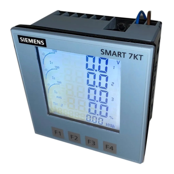
SMART 7KT0310 Manual Technical specification Display Type and specifics • Large backlit Liquid Crystal display • 4 Lines with 4 digits each to show measured values • 5th Line with 8 digits to show energy values • Graph for current loading indication Size of display (mm x mm) 60.3 mm x 60.3 mm LCD Indications Integration of energy PRG Unit is in configuration menu Communication in progress MAX DMD Maximum and Minimum Demand Power Display update time 1 sec. for all parameters Display scrolling Automatic or Manual (Programmable) Password protected Wiring input 3 Ø - 4 wire, 3 Ø - 3 wire, 1 Ø - 2 wire Measuring inputs Rated input voltage 11 to 300V AC (L-N); 19 to 519V AC (L-L); Installation Category III (600V) Frequency range... - Page 6 SMART 7KT0310 Manual Measured variables Measured variable On display On communication ● ● Voltage V , V ● ● Current ● ● Neutral current ● ● Frequency ● ● Power factor ● ● Active power ● ● Reactive power ● ● Apparent power ● ● Active energy (Import, Export, Total) ● ●...
-
Page 7: Installation
SMART 7KT0310 Manual Assembly Installation For installing the meter Prepare the panel cutout with proper dimensions as shown below. OUTLINE PANEL CUTOUT FRONT PANEL DESCRIPTION Dimensions (in mm) Dimensions (in mm) 91.5 1. Insert unit into the panel 2. Position the clamps (as shown in the 3. Push/Slide all 4 clamps towards the panel figure) and push the same into the slots evenly till the lowest possible tooth of in their respective locations. the clamp is engaged. Ensure the meter is properly tightened and it does not move. -
Page 8: Wiring Guidelines
SMART 7KT0310 Manual Installation Guidelines 1. This equipment, being built-in-type, normally becomes a part of main control panel and in such case the terminals do not remain accessible to the end user after installation and internal wiring. 2. Conductors must not come in contact with the internal circuitry of the equipment or else it may lead to a safety hazard that may in turn endanger life or cause electrical shock to the operator. 3. Circuit breaker or mains switch must be installed between power source and supply terminals to facilitate power ‘ON’ or ‘OFF’ function. However this switch or breaker must be installed in a convenient position normally accessible to the operator. 4. Before disconnecting the secondary of the external current transformer from the equipment, make sure that the current transformer is short circuited to avoid risk of electrical shock and injury. 5. The equipment shall not be installed in environmental conditions other than those mentioned in this manual. 6. The equipment does not have a built-in-type fuse. Installation of external fuse of rating 275V AC / 0.5Amp for electrical circuitry is highly recommended. 7. Remove the scratch-guard from the meter display during commissioning of the panel. Wiring Guidelines 1. To prevent the risk of electric shock, power supply to the equipment must be kept OFF while doing the wiring arrangement. 2. Wiring shall be done strictly according to the terminal layout. Confirm that all connections are correct. 3. Use lugged terminals. 4. To reduce electromagnetic interference use of wires with adequate ratings and twists of the same in equal size shall be made with shortest connections. 5. Layout of connecting cables shall be away from any internal EMI source. -
Page 9: Circuit Diagram
SMART 7KT0310 Manual Connection RS485 CONNECTIONS DIAGRAM Circuit Diagram 3 Phase 4-Wire (commonly used) 3 Ø - 4 Wire, 3 CT’S and 3 PT’S 3 Ø - 4 Wire, 3 CT’S RS485 RS485 SMART 7KT SMART 7KT V1 V2 Voltage upto 500V without PT Voltage 100V-500kV with PT LINE LOAD LINE LOAD... - Page 10 SMART 7KT0310 Manual Circuit Diagram (Continued) 3 Phase 3-Wire 1 Phase 2-Wire 3 Ø - 3 Wire, 2CTs and 2PTs 1 Ø - 2 Wire, 1 CT RS485 RS485 SMART 7KT SMART 7KT LINE LOAD LINE LOAD # All Fuse Type: 0.5A, Class gG...
- Page 11 SMART 7KT0310 Manual Configuration There are 4 dedicated keys labelled as F1, F2, F3, F4. Use these 4 keys to read meter parameters. Simply press these keys to read the parameters. The keys have multiple assignments. Function assignments and key labeling change according to the context of operator input. A short press on the key triggers the function once. Holding the key down for longer switches on the autorepeat function after approximately 1 s. The function of the key is triggered repeatedly while the key is held down. Autorepeat is useful, for example, for fast incrementing of values when parameterizing the device. For reading serial number Press F3 key for 5 sec. to display 8-digit serial number only for 5 sec. at 5th line of display Automatic / manual mode Press F4 key for 3 seconds to toggle between Automatic and Manual mode. Note: By default, unit operates in automatic mode. In automatic mode online pages scroll automatically at the rate of 5 seconds per page. In automatic mode when any key is pressed, unit temporarily switches to manual mode and the appropriate page is displayed. If any key is not pressed for 5 sec, unit resumes automatic mode. Password to start configuration When the meter is brought into the configuration mode by pressing keys F3+F4, the first page that is displayed is the password page which shows the password 0000. Enter the password 1000 which is the default factor-set password by pressing the F1 key to move curser left or right by one digit at a time and F2 or F3 keys for increasing or decreasing parameter values. After you enter the password of 1000, press F4 key to go to the next page which is the password change page and continue with parameterization. For the configuration setting mode Press F3 + F4 keys for 3 seconds to enter or exit from the Configuration menu.
- Page 12 SMART 7KT0310 Manual Parameterization with function keys Config. Factory Config. Factory Function Range or Selection Function Range or Selection page Setting page Setting Password 0000 to 9998 1000 16.11 Page sequence 11 1 to 22 Change Password No / Yes 16.12 Page sequence 12 1 to 22 New Password 0000 to 9998 1000 16.13 Page sequence 13...
- Page 13 SMART 7KT0310 Manual Reading of parameters Screen Key Press Description number Press F1 to Displays line to neutral voltage of three phase and average line to neutral voltage. navigate to each Displays line to line voltage of three phase and average line to line voltage. screen Displays total percentage harmonics of line to neutral voltage of three phase and average line to neutral voltage. Displays total percentage harmonics of line-to-line voltage of three phase and average line to line voltage. Displays phase current of three phase and neutral current. Displays phase maximum current demand of three phase and average current. Displays total percentage harmonic of current of three phase and average phase current. Note: 1) For 3 Ø 3 wire system, only second, fourth, fifth, sixth and seventh screens will be available. Displays average current instead of neutral current on screen number 5. 2) For 1 Ø 2 wire system, only first, third, fifth sixth and seventh screens will be available. Press F2 to Displays voltage, current, power factor of first phase and frequency. navigate to each Displays voltage, current, power factor of second phase and frequency.
- Page 14 SMART 7KT0310 Manual Reading of parameters (Continued) Screen Key Press Description number Press F4 to Displays import active energy of first phase. navigate to each Displays import active energy of second phase. screen. The Displays import active energy of third phase. energy values will be visible on the Displays export active energy of first phase. 5th line of the Displays export active energy of second phase. screen Displays export active energy of third phase. Displays total import active energy of three phase. Displays total export active energy of three phase. Displays total net active energy of three phase. Displays import reactive energy of first phase. Displays import reactive energy of second phase. Displays import reactive energy of third phase. Displays export reactive energy of first phase. Displays export reactive energy of second phase. Displays export reactive energy of third phase. Displays total import reactive energy of three phase. Displays total export reactive energy of three phase. Displays total net reactive energy of three phase. Displays apparent energy of first phase. Displays apparent energy of second phase. Displays apparent energy of third phase.
-
Page 15: Communication Parameters
SMART 7KT0310 Manual Communication Protocol and interface Connection diagram for communication Protocol: Modbus RTU Interface: Integrated RS485 interface Communication parameters Communication address 1 to 255 Master Transmission mode Half duplex Data types Float and Integer Transmission distance 500m maximum RS485-RS232 Transmission Speed 300, 600, 1200, 2400, 4800, Suggested Converter 9600, 19200 (in bps) terminating resistor (120 ohm, ¼ watt) Parity None, Odd, Even Stop bits... - Page 16 SMART 7KT0310 Manual Modbus register addresses list (Continued) Address Hex Address Parameter Address Hex Address Parameter 30086 0x56 kWh2 (Imp) 30193 0C1 27th Harmonic of V1N 30088 0x58 kWh3 (Imp) 30195 0C3 28th Harmonic of V1N 30090 0x5A kWh1 (Exp) 30197 0C5 29th Harmonic of V1N 30092 0x5C kWh2 (Exp) 30199 0C7 30th Harmonic of V1N 30094 0x5E kWh3 (Exp)
- Page 17 SMART 7KT0310 Manual Modbus register addresses list (Continued) Address Hex Address Parameter Address Hex Address Parameter 30293 125 17th Harmonic of V3N 30393 189 7th Harmonic of V23 30295 18th Harmonic of V3N 30395 8th Harmonic of V23 30297 129 19th Harmonic of V3N 30397 9th Harmonic of V23 30299 20th Harmonic of V3N 30399 10th Harmonic of V23 30301 21st Harmonic of V3N...
- Page 18 SMART 7KT0310 Manual Modbus register addresses list (Continued) Address Hex Address Parameter Address Hex Address Parameter 30493 27th Harmonic of V31 30593 251 17th Harmonic of I2 30495 28th Harmonic of V31 30595 253 18th Harmonic of I2 30497 29th Harmonic of V31 30597 255 19th Harmonic of I2...
- Page 19 SMART 7KT0310 Manual Modbus register addresses list (Continued) Readable / writable parameters: [Data Structure: Integer] Length Address Parameter Range Address (Register) 40000 0x00 Password Min value: 0 Max value: 9998 40001 0x01 N/W Selection Value: 0 Meaning: 3P4W Value: 1 Meaning: 3P3W Value: 2 Meaning: 1P2W-P1 Value: 3 Meaning: 1P2W-P2 Value: 4 Meaning: 1P2W-P3...
-
Page 20: Maintenance
Maintenance Guidelines • The equipment should be cleaned regularly to avoid blockage of ventilating parts. • Clean the equipment with a clean dry or damp cloth. Do not use any cleaning agent other than water. Disposal and recycling Dispose of or recycle the module in accordance with the applicable laws and regulations in your country. - Page 21 These instructions do not purport to cover all details or variations in Siemens. Any statements contained herein do not create new warranties equipment, or to provide for every possible contingency in connection or modify the existing warranty. with installation, operation, or maintenance. Should additional Trademarks - Unless otherwise noted, all names identified by ® are information be desired, please contact the local Siemens sales office. The registered trademarks of Siemens AG or Siemens Industry, Inc. The contents of this instruction manual shall not become part of or modify remaining trademarks in this publication may be trademarks whose use any prior or existing agreement, commitment, or relationship. The by third parties for their own purposes could violate the rights of the sales contract contains the entire obligation of Siemens. The warranty owner. contained in the contract between the parties is the sole warranty of Customer Care Toll free no. 1800 209 0987 Email: ics.india@siemens.com SACHIN ENTERPRISE Siemens Ltd. Product development is a continuous process. Consequently the data indicated in this Operating Instructions is subject to change without prior notice. For latest issue contact our sales offices.