Table of Contents
Advertisement
Quick Links
Advertisement
Table of Contents

Related Manuals for Siemens SITRANS LC500


Summary of Contents for Siemens SITRANS LC500
- Page 1 Capacitance Transmitters SITRANS LC500 Operating Instructions 05/2012 SITRANS...
- Page 2 The user is responsible for all changes and repairs made to the device by the user or the user’s agent. • All new components are to be provided by Siemens Milltronics Process Instruments. • Restrict repair to faulty components only.
-
Page 3: Table Of Contents
Probe Configuration ......................17 SITRANS LC500 Electrode (Probe) Characteristics ..............17 Electrode Assembly ..........................18 Process Connections ........................18 Seal Types .............................18 Process Connection and Seal Configuration of SITRANS LC500 ........18 Pressure and Temperature Considerations ................19 Non-standard applications .......................20 Installation .........................21 Handling Precautions ...........................21 Handling Electrodes ..........................22... - Page 4 Applications for Solid-state Output ....................33 Switch Protection (Diode) ......................34 Factory Settings .............................34 Settings: ............................34 The SITRANS LC500 User Interface ................36 The LCD (display) ...........................36 How to access the data: ........................37 Menu Levels 00 to 0F and 10 to 1F ..................37 The rotary switch ...........................38...
- Page 5 Appendix D: Block Diagram, and Correlation table, mA to % ........82 Correlation Table: 0% - 100% to 4-20 mA or 20-4 mA ..............83 Appendix E: SITRANS LC500, alternate versions and application details ....84 Cable version (non-insulated)(7ML5513) ................84 Cable version (insulated)(7ML5513) ..................85 Extended cable version with rod sensor (7ML5523) ............86...
- Page 6 Appendix F: Approvals ....................105 NAMUR recommendation NE 43 ..................105 Control Drawing FM/CSA Approval ....................106 SITRANS LC500 ..........................106 Glossary ..........................107 Index ..........................109 Quick Reference: SITRANS LC500 ................111 Quick Start ............................111...
-
Page 7: Safety Notes
The Manual Notes: • Please follow the installation and operating procedures for a quick, trouble-free installation and to ensure the maximum accuracy and reliability of your SITRANS LC500. • This manual applies to the SITRANS LC500 only. • This product is intended for use in industrial areas. Operation of this equipment in a residential area may cause interference to several frequency based communications. -
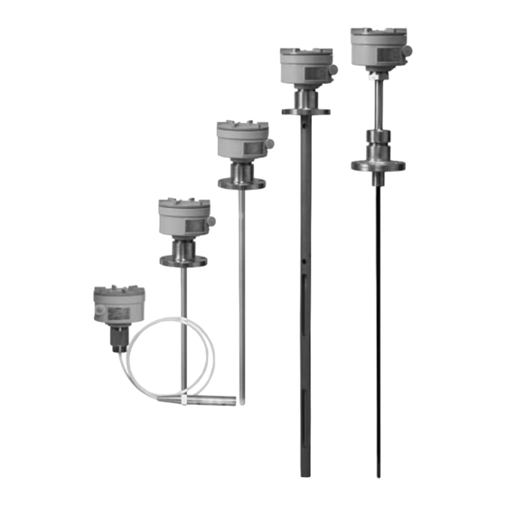
Page 8: Application Examples
This manual will help you set up your SITRANS LC500 for optimum performance. We always welcome suggestions and comments about manual content, design, and accessibility. Please direct your comments to techpubs.smpi@siemens.com. For other Siemens Milltronics level measurement manuals, go to: www.siemens.com/level and look under Level Measurement. -
Page 9: Abbreviations And Identifications
0% equivalent value Range Value Secondary Variable Upper SVURV 100% equivalent value Range Value Transmitter Variable Upper Range Value value for 100% 20 mA above which no PV is Upper Sensor Limit anticipated 7ML19985GE04 SITRANS LC500 – OPERATING INSTRUCTIONS Page 3... -
Page 10: Sitrans Lc500 Overview
SITRANS LC500 can be used as a level controller, by connecting the mA output and/or the solid-state switch to a relay, and activating a pump via an auxiliary power circuit. -
Page 11: Technical Specifications
0.1% full scale Repeatability 0. 1 % actual measurement Temperature stability 0.15 pF (0pF) or <0.25% (typically <0.1%) of actual measurement value, whichever is greater over the full temperature range of the transmitter 7ML19985GE04 SITRANS LC500 – OPERATING INSTRUCTIONS Page 5... - Page 12 0 to 9, A to F Push-buttons: RED (+), BLUE (–) used in conjunction with rotary switch, for programming menu items Communications HART Communication protocol HART® is a registered trademark of the HART Communications Foundation. Page 6 SITRANS LC500 – OPERATING INSTRUCTIONS 7ML19985GE04...
- Page 13 93 for a table showing flange sizes. Only available as Rod version, max. length 1500 mm (59”), and only for use in applications where pH 7. Teflon® is a registered trademark of Dupont. 7ML19985GE04 SITRANS LC500 – OPERATING INSTRUCTIONS Page 7...
- Page 14 Div. 1, Gr. A,B,C,D T4] no longer available. For LC500 devices purchased prior to June 2008 with IS approval, refer to Instruction Manual 7ML19985GE01, Edition 1.2. Go to www.siemens.com/level. From the LC500 product page, search the Instructions and Manuals archive.
-
Page 15: Transmitter
The SITRANS LC500 variable frequency oscillator The SITRANS LC500 probe is equipped with a variable frequency oscillator which responds to the capacitance: a change in capacitance is registered as a change in frequency. The relationship between capacitance and frequency is inverse, resulting in high resolution and accuracy. - Page 16 As the product level rises the capacitance will increase. Non-conductive or conductive contents In practice, the SITRANS LC500 probe is usually insulated. If the vessel contents are non- conductive, the dielectric is composed of the vessel contents and the insulation, and the separation distance is from the probe to the tank wall.
-
Page 17: The Sitrans Lc500 Electrode
The SITRANS LC500 electrode The SITRANS LC500 electrode, comprising a measurement section and an active shield section, is the primary sensor of the system. It supplies the electrical capacitance value of the measurement section relative to the environment (tank wall or stilling well). - Page 18 This increases the achievable resolution of the measurement, since any change in level will be greater relative to the length of the measurement section. Page 12 SITRANS LC500 – OPERATING INSTRUCTIONS 7ML19985GE04...
-
Page 19: Application: Sitrans Lc500
The entire SITRANS LC500 transmitter is potted in epoxy resin as part of the intrinsic safety protection. The potting also protects the electronics against mechanical vibration and moisture influences. The transmitter is connected to the electrode by a mini coaxial cable, and grounded to a connection point inside the enclosure. -
Page 20: Level Measurement
The LCD displays the value as mA, or pF, or percent, depending on the setting for the transmitter variable (TV). If you are using HART, you have the option to define the units. Page 14 SITRANS LC500 – OPERATING INSTRUCTIONS 7ML19985GE04... -
Page 21: Interface Measurement
Set the time delay to 10 seconds (for example): the alarm will be on only after the surface has been at 80% for at least 10 seconds. • Reset the hysteresis for 70 (for example): the unit will ignore small surface fluctuations between 79 and 80%. 7ML19985GE04 SITRANS LC500 – OPERATING INSTRUCTIONS Page 15... -
Page 22: Fault Signalling
It can then be used to activate a failure alarm, or a level switch. (See page 102 for details of an application using SITRANS LC500 as a level indicator, with the two-state output connected to a relay that activates a pump.) NAMUR recommendation NE 43 on page 105 for more details. -
Page 23: Probe Configuration
SITRANS LC500 Electrode (Probe) Characteristics Apply to all general connection configurations: • The standard SITRANS LC500 insulated electrode is designed for use in both conducting and non-conducting liquid applications. • Most electrodes consist of an active shield portion and a measurement portion, which combine to form the complete electrode. -
Page 24: Electrode Assembly
Any standard process connection is available with the SITRANS LC500, and special versions can be fabricated to match the mounting and application requirements. A wide range of threaded and flanged fittings is available. (Contact your local Siemens Milltronics representative for details, or check our website at: www.siemens-milltronics.com.) -
Page 25: Pressure And Temperature Considerations
Enamel probes are recommended when the process temperature exceeds 200 C, and/or in combination with very high pressure. Note: Consult your Siemens Milltronics representative if the material to be measured may be incompatible with the SITRANS LC500 materials of construction. -
Page 26: Non-Standard Applications
Use a stilling well as linearizer. horizontal-cylindrical tanks. Highly corrosive materials requiring no Use flange mount with PFA Facing (7ML5517). metallic wetted parts. Appendix E: SITRANS LC500, alternate For more details on alternate configurations, see, versions and application details on page 84. Page 20 SITRANS LC500 –... -
Page 27: Installation
At the process connection or flange Note: Unit shown is LC500 Threaded Rod Version. Handling precautions apply to all LC500 units with rods longer than 2 m (6.5 ft). 7ML19985GE04 SITRANS LC500 – OPERATING INSTRUCTIONS Page 21... -
Page 28: Handling Electrodes
Mounting Instructions The SITRANS LC500 is easily installed: simply mount the instrument on the process connection of the vessel. Notes: •... -
Page 29: Process Cautions
(rigid design only). • Various process connection materials • Both Rod and Cable versions Appendix E: SITRANS LC500, alternate versions and application details , page 84 onward, for details on dimensions, and for application examples. 7ML19985GE04 SITRANS LC500 – OPERATING INSTRUCTIONS... -
Page 30: Interconnection
The loop-circuit will withstand voltages up to 250 Vac/Vdc without any damage. The SITRANS LC500 uses a switched power supply circuit, which makes the most efficient use of the available power present on the terminals. If the signal current is low,... -
Page 31: Cable
For a multi-drop application, where the measuring supply is fixed to 4 mA, the voltage on the terminals of the SITRANS LC500 should be at least 12 Volts. The loop circuit is completely isolated from the measurement circuit. It is designed so that the internal capacitance and inductance on the terminals are isolated and do not factor in safety calculations. - Page 32 With three devices, at 3 x 68 nF, the allowable cable length will be considerably limited. Notes: • If the device is part of a multi-drop setup, the SITRANS LC500 sets the current to 4 mA, which inhibits analog signalling, including fault signalling. •...
-
Page 33: Terminals
Terminals The SITRANS LC500 is equipped with two terminal blocks, both insensitive to polarity. One terminal block is intended for connecting the instrument cable (loop power). The other terminal block provides the solid-state switch output. Connecting SITRANS LC500 The processor integrated circuit is covered by a label which contains product information and which also acts as a protective seal against moisture. -
Page 34: Connection Diagram
Feed cable through dome nut and clamping insert. Fold braided shield over clamping insert. Make sure that braided shield overlaps the O-ring by 3/32" (2 mm) and covers the entry 360 degrees. Push clamping insert into body and tighten dome nut. Assemble into housing. Page 28 SITRANS LC500 – OPERATING INSTRUCTIONS 7ML19985GE04... - Page 35 Ensure that the middle nut (2) does not rotate when tightening the backnut (1). Note: The deluge seal on this gland locates on assembly and requires no further action. Locate shroud over cable gland, if applicable. 7ML19985GE04 SITRANS LC500 – OPERATING INSTRUCTIONS Page 29...
-
Page 36: Protection For Solid-State Switch
1 mm • The SITRANS LC500 measurement circuit is completely isolated from the loop circuitry: this allows either line of the loop circuit to be grounded if requirements for Ex safety are followed and if the power supply voltage is less than 33 Vdc. -
Page 37: Grounding Examples: Sitrans Lc500
If the metal tank is reliably grounded, connect the ground lug on the SITRANS LC 500 to the earth ground on the tank as shown. (See page 28 for connection diagram.) metal 7ML19985GE04 SITRANS LC500 – OPERATING INSTRUCTIONS Page 31... -
Page 38: Cathodically Protected Metal Tanks
Safety Grounding The safety grounding requirements are determined by the application and the connected instruments. The SITRANS LC500 transmitter does not have any special requirements due to the galvanic separation between the measurement section and the loop section. Depending on the DCS characteristics, there are three possible grounding options: Page 32 SITRANS LC500 –... - Page 39 DIN rail inside a customer-supplied enclosure located in the non-hazardous area. Example 1 If no specific Ex conditions apply, the SITRANS LC500 can be directly connected to the DCS. The supply voltage, however, should remain within the limits set by the SITRANS LC 500.
-
Page 40: Communications
The internal diagnostic functions continuously monitor the operation of the transmitter. An error signal is generated if a failure or irregularity occurs. The SITRANS LC500 sends the signal current according to the NAMUR NE 43 recommendation. During normal operation the current remains within the range from 3.8 to 20.5 mA. -
Page 41: Applications For Solid-State Output
In menu 0E and menu 0F, you set the Upper and Lower Range Values (URV and LRV) for relay operation. Within that range, the solid-state switch has independent settings for Calibration using push-button adjustment on page 43. Fault Signalling on page 16 for details of fault conditions. 7ML19985GE04 SITRANS LC500 – OPERATING INSTRUCTIONS Page 35... -
Page 42: Switch Protection (Diode)
Factory Settings The SITRANS LC500 has a number of default factory settings. If the required settings for the application are known, the settings can be modified during final testing. Note:... - Page 43 An interruption of the measuring connection will be detected: a loose or interrupted connection results in up to 0.5 pF capacitance, which is below the adjusted LSL and thus signals a FAULT condition. 7ML19985GE04 SITRANS LC500 – OPERATING INSTRUCTIONS Page 37...
-
Page 44: The Sitrans Lc500 User Interface
The SITRANS LC500 User Interface The SITRANS LC500 user interface consists of the display (LCD), the rotary switch, and two push-buttons. The rotary switch enables you to select a particular item and/or variable for read-out and/or adjustment: the push-buttons allow you to select and/or alter a read-out or a value. -
Page 45: How To Access The Data
70 Digital Signalling Mode page 71 Digital Fault Signalling page 72 Output Signal Processing Test page 73 Factory Settings page 73 Miscellaneous Range Inversion page 74 Keylock Level page 74 Non-operational Spare 7ML19985GE04 SITRANS LC500 – OPERATING INSTRUCTIONS Page 37... -
Page 46: The Rotary Switch
LCD appears. (You have to press longer than the debounce time to have the action accepted: the debounce time varies according to the menu item selected.) Page 38 SITRANS LC500 – OPERATING INSTRUCTIONS 7ML19985GE04... -
Page 47: Transmitter Variables
Transmitter Variable 1 (TV1) is a computed variable: the dynamic value is a computed derivative from the range settings for TV0. Transmitter Variable User-defined Functions Units URV, LRV, Damping, USL and LSL Can be user-defined 7ML19985GE04 SITRANS LC500 – OPERATING INSTRUCTIONS Page 39... -
Page 48: Start-Up: Sitrans Lc500
For instruments without a stilling well, the 0% setting needs to be calibrated after the device is installed, and with the tank/vessel empty. Calibration is also sometimes neces- sary after installing a SITRANS LC500 fitted with a stilling well, although in most cases the 0% setting is calibrated at the factory. - Page 49 Threshold Threshold for Solid-state for Solid-state Operating Var 3 Keys Level 00 < - > 100 00 < - > 100 Point to 75% Point to 25% Mode Read-Out Default Disabled Disabled 7ML19985GE04 SITRANS LC500 – OPERATING INSTRUCTIONS Page 41...
-
Page 50: Menu Levels 0 And 1
• Calibrate value for 0% • Calibrate value for 100% • Set display for dynamic PV (primary variable): select values displayed as percent or units • SITRANS LC500 is ready to operate Page 42 SITRANS LC500 – OPERATING INSTRUCTIONS 7ML19985GE04... -
Page 51: Calibration Using Push-Button Adjustment
For instruments without a stilling well, the 0% setting needs to be calibrated after the device is installed, and with the tank/vessel empty. Calibration is also sometimes necessary after installing a SITRANS LC500 fitted with a stilling well, although in most cases the 0% setting is calibrated at the factory. - Page 52 As you step the capacitance down, you decrease the range and reduce the span, so the percentage increases in relation to the smaller span. Therefore the (+) and (–) buttons appear to function in reverse. Page 44 SITRANS LC500 – OPERATING INSTRUCTIONS 7ML19985GE04...
- Page 53 To see the value displayed as pF, select menu 01 and increase or decrease the value till Pv = 0. The SITRANS LC500 is now ready to operate. For a table showing the different functions available, and the combinations of switch position and button presses used to carry out Appendix A: Menu these functions, see page 41.
-
Page 54: Calibration Using Hart
Calibration using HART The SITRANS LC500 transmitter can be calibrated using HART, with a HART communicator ; a laptop running Simatic PDM, or with the Host system (DCS). The local circumstances determine the manner in which calibration takes place. If the circumstances allow the product to be brought to the 0% and 100% point level, calibration is simple. - Page 55 Example 2 For situations where the capacitance values are known in advance. Switch on the 275 and establish connection with the SITRANS LC500. a. Select: Online b. Select: Device setup c. Select: Diag service d. Select: Calibration e. Select: Enter values f.
- Page 56 = 47.22 pF. 3. Adjust URV and LRV by following the steps in Example 2. If the DCS and/or the 275 are fitted with the Device Descriptor for the SITRANS LC500, more functions can be used. The available functions are...
- Page 57 Read analog threshold settings (156) Write digital threshold settings (157) Read digital threshold settings (160) Write timers analog signalling (161) Read timers analog signalling (162) Write timers digital signalling (163) Read timers digital signalling 7ML19985GE04 SITRANS LC500 – OPERATING INSTRUCTIONS Page 49...
-
Page 58: Maintenance
Test function Auto Self-testing SITRANS LC500 continuously performs a variety of tests to verify that the device is functioning correctly. These include a test where a known capacitor is applied to the input of the device. The internal results must match the known capacitance value. If a deviation is detected the Fault/Failure can be flagged with a pre-set loop-current (user configurable) and as a status in each HART message. - Page 59 If it does, switch the output current to 4 mA and check the current through the loop, then to 20 mA and check the current through the loop. After the test, replace the plug. 7ML19985GE04 SITRANS LC500 – OPERATING INSTRUCTIONS Page 51...
-
Page 60: Troubleshooting: Sitrans Lc500
If the LCD displays a negative reading, typically around minus 300 pF, this often indicates a short circuit in the probe assembly: • check the enclosure and make sure no water has got in • check that all the connections in the probe assembly are solid Page 52 SITRANS LC500 – OPERATING INSTRUCTIONS 7ML19985GE04... -
Page 61: Error Messages And Error Codes
ADC Usually indicates a fault in the connection PV value is outside the limits set between the transmitter module and the probe (USL and LSL) (the coaxial connector is off) 7ML19985GE04 SITRANS LC500 – OPERATING INSTRUCTIONS Page 53... -
Page 62: Notes
Notes Page 54 SITRANS LC500 – OPERATING INSTRUCTIONS 7ML19985GE04... -
Page 63: Appendix A: Menu Groups
Processing Test Menu 11 Menu 12 Menu 19 Menu 1F see page 73 see page 73 see page 74 see page 74 Only 28 of the possible 32 items are currently used. 7ML19985GE04 SITRANS LC500 – OPERATING INSTRUCTIONS Page 55... -
Page 64: Menu Items
10, 100, and 1000 (1E3), or down to 0.1 and 0.01. 3. Press and hold both buttons simultaneously to restore the value to U:1.0 Page 56 SITRANS LC500 – OPERATING INSTRUCTIONS 7ML19985GE04... - Page 65 Press and hold a button to start a repeat function, or: Press and hold both buttons simultaneously to take the current PV reading as the new setting. For example, in an application with an agitated surface. 7ML19985GE04 SITRANS LC500 – OPERATING INSTRUCTIONS Page 57...
- Page 66 The Delta Range Setting allows you to commission the unit for overfill or underfill protection where it is impossible to bring the product to those levels in normal process conditions. This feature is not normally used for the SITRANS LC500. Overfill protection is used in applications where the probe is normally uncovered. Delta Range Setting adds the minimum span to the Lower Range Value: the result is used to update the Upper Range Value.
- Page 67 Press and hold a button for a prolonged time to start a repeat function. When the new setting exceeds that of the Limit Settings (Menu 0C and 0B), the new value is rejected and the previous value remains unchanged. 7ML19985GE04 SITRANS LC500 – OPERATING INSTRUCTIONS Page 59...
- Page 68 If the internal diagnostics detect a fault or failure, the display alternates between the PV value and the fault/failure message ‘Flt’ . If the product level goes outside the limit settings, then the display alternates between the PV value and ‘ooL’ . Alternatively, if the simulation Page 60 SITRANS LC500 – OPERATING INSTRUCTIONS 7ML19985GE04...
- Page 69 Menu Left Switch Description Values Item Arrow Position 0 * TVO (units are pF) Transmitter Variable TV1 (units are user definable selection for PV only via HART) TV0 (values displayed as %) 7ML19985GE04 SITRANS LC500 – OPERATING INSTRUCTIONS Page 61...
- Page 70 Dynamic Value simultaneously Invalid Display selection shows 0.00 The units are pF: there is no other option. TV2 and TV3 are not currently used, but are available for future development. Page 62 SITRANS LC500 – OPERATING INSTRUCTIONS 7ML19985GE04...
-
Page 71: Analog Output Signalling (Proportional Or 2-State): Menu Level 0
Menu 08 for an uncovered probe. Whenever the level rises above the Lower Threshold Setting before the timer expires, the timer is restarted. As an extra identifier, a downward running A is displayed to the right of the value. 7ML19985GE04 SITRANS LC500 – OPERATING INSTRUCTIONS Page 63... - Page 72 2. Set the rotary switch to 5. 3. Press the RED (+) or BLUE (–) button to increase or decrease the value. or: Press and hold a button to start a repeat function. Page 64 SITRANS LC500 – OPERATING INSTRUCTIONS 7ML19985GE04...
-
Page 73: Analog Signalling Mode (2-State): Menu Level 0
C: Hi selects a 20 mA signal for a covered probe, which switches to 4 mA if the probe becomes uncovered. • C: Lo selects a 4 mA signal for a covered probe, which switches to 20 mA if the probe becomes uncovered. 7ML19985GE04 SITRANS LC500 – OPERATING INSTRUCTIONS Page 65... - Page 74 The loop-current will be between 3.8 and 20.5 mA, and will saturate to one of these values if the level goes beyond the Upper or Lower range settings. Page 66 SITRANS LC500 – OPERATING INSTRUCTIONS 7ML19985GE04...
- Page 75 To change the mode to 2-state Low, press the BLUE (–) button for more than a second: the display reads F: Lo. In the case of a fault/failure the loop-current goes to 3.6 mA. Fault Signalling For detailed information, see on page 16. 7ML19985GE04 SITRANS LC500 – OPERATING INSTRUCTIONS Page 67...
-
Page 76: Digital Output Signalling (Solid-State Output): Menu Level 1
2. Press the RED (+) or BLUE (–) button to increase or decrease the value. or: Press and hold a button to start a repeat function. or: Press both buttons simultaneously to toggle the value between minimum (0) and maximum (100). Page 68 SITRANS LC500 – OPERATING INSTRUCTIONS 7ML19985GE04... - Page 77 When the solid-state switch control (Menu 17) is disabled, menu 15 displays only - - - -. When the solid-state switch control is enabled, menu 15 displays the Upper Threshold setting in percent. As an extra identifier, an upward ramp is displayed to the right of the value. 7ML19985GE04 SITRANS LC500 – OPERATING INSTRUCTIONS Page 69...
- Page 78 1. Set the rotary switch to 6. 2. Press the RED (+) or BLUE (–) button to increase or decrease the value. or: Press and hold a button to start a repeat function. Page 70 SITRANS LC500 – OPERATING INSTRUCTIONS 7ML19985GE04...
- Page 79 If digital fault signalling is enabled at menu 18, it takes precedence, and no equal sign will appear in the display for menu 17 if the device is responding to a fault. 7ML19985GE04 SITRANS LC500 – OPERATING INSTRUCTIONS Page 71...
- Page 80 A colon at the extreme left of the display appears while the button is pressed to indicate when a setting is accepted, for example : S: cc. Page 72 SITRANS LC500 – OPERATING INSTRUCTIONS 7ML19985GE04...
-
Page 81: Miscellaneous
Set the rotary switch to 2. To restore the factory settings, press both buttons simultaneously to change the LCD to ‘do it’ and hold both buttons for more than one second. When the buttons are released, the LCD displays FAC A. 7ML19985GE04 SITRANS LC500 – OPERATING INSTRUCTIONS Page 73... - Page 82 PL 2 PH 2 adjustments Disables all PL 3 PH 3 changes 1. Set the rotary switch to F. 2. Press the RED (+) or BLUE (–) button to change the setting. Page 74 SITRANS LC500 – OPERATING INSTRUCTIONS 7ML19985GE04...
-
Page 83: Appendix B: Lcd Display Examples
Solid-state switch / current-loop output functions PL 0 due to Faults are disabled: F: – – Simulation is active. Transmitter Variable TVO driven by simulation value: Current-loop, current goes to 22 mA when Fault detected: 7ML19985GE04 SITRANS LC500 – OPERATING INSTRUCTIONS Page 75... -
Page 84: Appendix C: Hart Documentation
HART Communication Foundation at www.hartcomm.org The SITRANS LC500 can be configured over the HART network using either the HART Communicator 275 by Fisher-Rosemount, or a software package. There are a number of different software packages available.The recommended software package is the Simatic Process Device Manager (PDM) by Siemens. -
Page 85: Sitrans Lc500 Dd Menu/Variable Organization
SITRANS LC500 DD Menu/Variable Organization Root Menu Device Setup Menu Process Variables Auto Calibration Menu Device setup menu Sensor digital value Process variables menu Applied rerange PV digital value Input percent range Diagnostics/service Keypad rerange PV upper range value A0 analog value... -
Page 86: Hart Response Code Information
Bit #0: Primary Variable Out of Limits This flag is set whenever the Transmitter Variable #0 (in pF), the Primary Variable exceeds the Sensor Limits returned with Command 14, Read Primary Variable Sensor Limits. Page 78 SITRANS LC500 – OPERATING INSTRUCTIONS 7ML19985GE04... -
Page 87: Hart Conformance And Command Class
HART Conformance and Command Class SITRANS LC500 transmitter Conformance and Command Class summary. Command Description Usage Number Conformance Class #1 Return Unique Identifier Universal Read Primary Variable Conformance Class #1A Return Unique Identifier Universal Read PV Current and Percent of Range... -
Page 88: General Transmitter Information
Read Delay Timers Digital Signalling General Transmitter Information Damping information The SITRANS LC500 transmitter implements damping on most of the transmitter variables. The damping setting may vary from 1 (shortest value) to 10000 (longest value). Non-volatile Memory Data Storage The flags byte of Command #0 referenced in the Universal Command Specification... -
Page 89: Multidrop Operation
MultiDrop operation The SITRANS LC500 transmitter supports MultiDrop Operation. Burst mode The SITRANS LC500 transmitter does not support Burst Mode. Units conversions The Transmitter Variable #0 Units are in pF and cannot be changed. The Transmitter Variable #1 Values may be set to any Units and Value with Command #140. -
Page 90: Appendix D: Block Diagram, And Correlation Table, Ma To
2-state max/min Lower Fault Delay recorded Threshold (menu 14) value (menu 16) Solid- Digital State reset Signalling Output Mode (menu 17) Fault Digital Fault/Failure (menu 18) SITRANS LC500 Block Diagram 7ML19985GE04 SITRANS LC500 – OPERATING INSTRUCTIONS Page 82... -
Page 91: Correlation Table: 0% - 100% To 4-20 Ma Or 20-4 Ma
Correlation Table: 0% - 100% to 4-20 mA or 20-4 mA Range 0 - 100 % Current in mA Range 100 - 0 % 10.4 11.2 12.0 12.8 13.6 14.4 15.2 16.0 16.8 17.6 18.4 19.2 20.0 7ML19985GE04 SITRANS LC500 – OPERATING INSTRUCTIONS Page 83... -
Page 92: Appendix E: Sitrans Lc500, Alternate Versions And Application Details
Appendix E: SITRANS LC500, alternate versions and application details Cable version (non-insulated)(7ML5513) Threaded Flanged transmitter/ transmitter/ electronics electronics stainless steel stainless steel cable cable ø 6 mm (0.24”) ø 6 mm (0.24”) stainless steel stainless steel weight weight ø 32 mm (1.26”) ø... -
Page 93: Cable Version (Insulated)(7Ml5513)
ø 12 mm (0.47”) stainless steel weight ø 25 mm (0.98”) ø 34.5 mm (1.36”) Applicable for both liquids and solids. Cable cannot be shortened. Weight is not part of measuring length. 7ML19985GE04 SITRANS LC500 – OPERATING INSTRUCTIONS Page 85... -
Page 94: Extended Cable Version With Rod Sensor (7Ml5523)
ø 48 mm (1.88”) stainless steel flexible tube Mounting eye option Flanged 20 mm mounting eye (0.79”) ø 12 mm (0.47”) ø 16 mm ø 25 mm (0.98”) (0.63”) ø 48 mm (1.88”) Page 86 SITRANS LC500 – OPERATING INSTRUCTIONS 7ML19985GE04... - Page 95 ø 35 mm (1.37”) 15 mm (0.60”) For Y02 lengths greater than 5000 mm (1.97”), cable is inactive and is not atively shielded. Insertion length Y01 = Y02 + measuring length + 92 mm (3.62”) 7ML19985GE04 SITRANS LC500 – OPERATING INSTRUCTIONS Page 87...
-
Page 96: Rod Version (7Ml5515)
Minimum Y02 (active shield length) = 50 mm (1.96”), minimum measuring length = 200 mm (7.87”) For Y02 lengths greater than 5000 mm (197”), cable is inactive and is not actively shielded. Insertion length Y01 = Y02 + measuring length + 15 mm (0.59”) Page 88 SITRANS LC500 – OPERATING INSTRUCTIONS 7ML19985GE04... - Page 97 ø 35 mm (1.38”) or ø 48 mm (1.89”) Minimum Y02 (active shield length) = 50 mm (1.96”), minimum measuring length = 200 mm (7.87”) Insertion length does not include any raised face/gasket face dimension. 7ML19985GE04 SITRANS LC500 – OPERATING INSTRUCTIONS Page 89...
-
Page 98: Enamel Rod Version (7Ml5515)
ø 16 mm (0.63”) ø 40 mm (1.57”) Flanged enamel probe ø 16 mm (0.63”) Minimum Y02 (active shield length) = 100 mm (3.94”), minimum measuring length = 250 mm (9.84”) Page 90 SITRANS LC500 – OPERATING INSTRUCTIONS 7ML19985GE04... -
Page 99: Enamel Rod Version With Stilling Well
ø 16 mm (0.63”) ø 40 mm (1.57”) 30 mm (1.18”) Inactive tip Minimum Y02 (active shield length) = 100 mm (3.94”), minimum measuring length = 250 mm (9.84”) 7ML19985GE04 SITRANS LC500 – OPERATING INSTRUCTIONS Page 91... -
Page 100: Remote Electronics With Mounting Bracket Option
½” NPT: 230 mm (9. 1 ”) With thermal isolator option With thermal isolator option (all versions) (all versions) With explosion-proof seal With explosion-proof seal option (all versions) option (all versions) thermal thermal isolator isolator Page 92 SITRANS LC500 – OPERATING INSTRUCTIONS 7ML19985GE04... -
Page 101: Flanges
Flange Standards Notes: • All measurements are given in mm • One (1) inch = 25.4 mm • For details, see drawings, technical data, and measuring probe details on pages 84 to 100. 7ML19985GE04 SITRANS LC500 – OPERATING INSTRUCTIONS Page 93... - Page 102 300 lb 1” 123.95 88.90 19.05 15.75 1½” 155.45 114.30 22.22 19.05 2” 165.10 127.00 19.05 20.57 3” 209.55 168.15 22.22 26.92 4” 254.00 200.15 22.22 30.23 6” 317.50 269.75 22.22 35.05 Page 94 SITRANS LC500 – OPERATING INSTRUCTIONS 7ML19985GE04...
- Page 103 4” 273.05 215.90 25.40 38.10 6” 355.60 292.10 28.58 47.75 900 lb 2” 215.90 165.10 25.40 38.10 3” 241.30 190.50 25.40 38.10 4” 292.10 234.95 31.75 44.45 6” 381.00 317.50 31.75 55.63 7ML19985GE04 SITRANS LC500 – OPERATING INSTRUCTIONS Page 95...
- Page 104 22.0 PN40 DN25 115.0 85.0 14.0 18.0 DN40 150.0 110.0 18.0 18.0 DN50 165.0 125.0 18.0 20.0 DN80 200.0 160.0 18.0 24.0 DN100 235.0 190.0 22.0 24.0 DN125 270.0 220.0 26.0 26.0 Page 96 SITRANS LC500 – OPERATING INSTRUCTIONS 7ML19985GE04...
- Page 105 øD øL (±1.0) (+1.0/-0.0) (±2.0) (±0.3 x N) PN63 DN50 180.0 135.0 22.0 26.0 DN80 215.0 170.0 22.0 28.0 DN100 250.0 200.0 26.0 30.0 DN125 295.0 240.0 30.0 34.0 7ML19985GE04 SITRANS LC500 – OPERATING INSTRUCTIONS Page 97...
- Page 106 (±1.0) (±0.3) (+3.0/-0.0) (+0.0/-0.5) (±0.8) 150 lb 1½” 127.0 98.55 15.88 15.75 2” 152.40 120.65 19.05 17.53 3” 190.50 152.40 19.05 22.35 4” 228.60 190.50 19.05 22.35 6” 279.40 241.30 22.22 23.88 Page 98 SITRANS LC500 – OPERATING INSTRUCTIONS 7ML19985GE04...
- Page 107 269.75 22.22 35.05 600 lb 1½” 155.45 114.30 22.22 22.35 2” 165.10 127.00 19.05 25.40 3” 209.55 168.15 22.22 31.75 4” 273.05 215.90 25.40 38. 1 0 6” 355.60 292.10 28.58 47.75 7ML19985GE04 SITRANS LC500 – OPERATING INSTRUCTIONS Page 99...
- Page 108 20.0 DN125 250.0 210.0 18.0 22.0 PN40 DN40 150.0 110.0 18.0 18.0 DN50 165.0 125.0 18.0 20.0 DN80 200.0 160.0 18.0 24.0 DN100 235.0 190.0 22.0 24.0 DN125 270.0 220.0 26.0 26.0 Page 100 SITRANS LC500 – OPERATING INSTRUCTIONS 7ML19985GE04...
-
Page 109: Applications Examples
The initial capacitance value at 0% (probe in air) is 12.7 pF, and the capacitance value for 100% (tank filled with oil) is 25.4 pF. After calibration: 12.7 pF 0% 4 mA or 20 mA 25.4 pF 100% 20 mA or 4 mA 7ML19985GE04 SITRANS LC500 – OPERATING INSTRUCTIONS Page 101... -
Page 110: Application: Level Indicator And Solid-State Switch Output
17 menu 16 (deactivation hysteresis) Lower Threshold Setting = 8% controlled 14.3 pF (menu 0E) LRV = 0% by menus (menu 0B) LSL 13 to 18. Page 102 SITRANS LC500 – OPERATING INSTRUCTIONS 7ML19985GE04... -
Page 111: Application: Analog Fault Signalling (2-State Output)
The mA reading can be stabilized if necessary by applying Damping (menu 0A): the increment value is controlled at menu 09. S:cc appears while the button is pressed. See menu 17 on page 71 for more details. 7ML19985GE04 SITRANS LC500 – OPERATING INSTRUCTIONS Page 103... - Page 112 8%, the probe is considered uncovered, and the output will switch to 4 mA. If the level drops below LSL, the fault signal will be 22 mA. F: Hi appears while the button is pressed. See Analog Fault Signalling (2-state) on page 67 for more details. Page 104 SITRANS LC500 – OPERATING INSTRUCTIONS 7ML19985GE04...
-
Page 113: Appendix F: Approvals
The application will determine which of these two ranges is more desirable. The SITRANS LC500 can be set for 3.6 mA, or 22 mA, as required It may also signal a process level outside the Upper and Lower Sensor Limits, if Fault the unit has been programmed for this. -
Page 114: Control Drawing Fm/Csa Approval
Control Drawing FM/CSA Approval SITRANS LC500 Page 106 SITRANS LC500 – OPERATING INSTRUCTIONS 7ML19985GE04... -
Page 115: Glossary
Many conductive liquids/electrolytes exhibit dielectric properties; the relative dielectric constant of water is 80. 7ML19985GE04 SITRANS LC500 – OPERATING INSTRUCTIONS Page 107... - Page 116 Notes Page 108 SITRANS LC500 – OPERATING INSTRUCTIONS 7ML19985GE04...
-
Page 117: Index
33 handling cautions 22 operating principles 9 external relay protection for solid-state switch 34 Simatic Process Device Manager 76 factory settings pressure and temperature considerations 19 restoring 73 values 34 7ML19985GE03 SITRANS LC500 – OPERATING INSTRUCTIONS Page 109... - Page 118 40 supply voltage requirements 24 system grounding referencing 29 test function details 50 transmitter damping 80 operating principles 9 specifications 5 transmitter variable selection 43 voltage power supply requirements 24 Page 110 SITRANS LC500 – OPERATING INSTRUCTIONS 7ML19985GE03...
-
Page 119: Quick Reference: Sitrans Lc500
For instruments without a stilling well, the 0% setting needs to be calibrated after the device is installed, and with the tank/vessel empty. Calibration is also sometimes neces- sary after installing a SITRANS LC500 fitted with a stilling well, although in most cases the 0% setting is calibrated at the factory. - Page 120 Threshold Threshold for Solid-state for Solid-state Operating Var 3 Keys Level 00 < - > 100 00 < - > 100 Point to 75% Point to 25% Mode Read-Out Default Disabled Disabled Page 112 SITRANS LC500 – OPERATING INSTRUCTIONS 7ML19985GE04...
- Page 121 For more information www.siemens.com/level www.siemens.com/weighing Siemens AG Subject to change without prior notice Industry Sector 7ML19985GE04 Rev. 4.0 1954 Technology Drive *7ml19985GE04* P.O. Box 4225 © Siemens AG 2012 Peterborough, ON Canada K9J 7B1 Printed in Canada email: techpubs.smpi@siemens.com www.siemens.com/processautomation...