
Related Manuals for Hitachi VK-S214R


Summary of Contents for Hitachi VK-S214R
- Page 1 No. 8301E VK-S214R VK-S214ER SERVICE MANUAL SPECIFICATIONS AND PARTS ARE SUBJECT TO CHANGE FOR IMPROVEMENT COLOR VIDEO CAMERA March 2003 Digital Media Division,Tokai...
-
Page 2: Table Of Contents
Table of Contents 6-1-4 Setting test equipment ......6-3 1 Safety Precaution for Repair ..... 1-1 6-1-5 Starting adjustment program (ZMAP) ..6-3 1-1 Cautions ........... 1-1 6-2 List of Adjustment Items ......6-5 1-2 Notes When Using Service Manual ..1-1 6-2-1 List of adjustments needed after 1-2-1 Value units used in parts list .... -
Page 3: Safety Precaution For Repair
The use of a substitute replacement component which does not have the same safety characteristics as the HITACHI recommended replacement one, shown in the parts list in this Service Manual, may create shock, fire, or other hazards. Product safety is continuously under review and new instructions are issued from time to time. -
Page 4: Identifications Of Sides A/B In Circuit Board Diagrams
Safety Precaution for Repair > Notes When Using Service Manual 1-2-3 Identifications of sides A/B in circuit board diagrams 1) Board having a pattern on one side and parts on both sides. Side A: Shows discrete parts, viewed from the pattern side. Side B: Shows leadless parts, viewed from the pattern side. -
Page 5: Electrostatic Protection Measures
Safety Precaution for Repair > Electrostatic Protection Measures 1-3 Electrostatic Protection Measures Semiconductor components, including optical pickups, may be damaged by static electricity charged on clothes, human body, etc. Take great care when handling it to avoid electrostatic damage. 1-3-1 Grounding for prevention of electrostatic damage Perform servicing in an environment where grounding is complete. -
Page 6: Lead-Free Solder
Safety Precaution for Repair > Lead-Free Solder 1-4 Lead-Free Solder To protect the global environment, lead-free solder is used in this product. Be sure to read the following before soldering. Caution Be sure to wear protective goggles so that no solder smoke or scattered solder enters the eye during servicing. -
Page 7: General Description
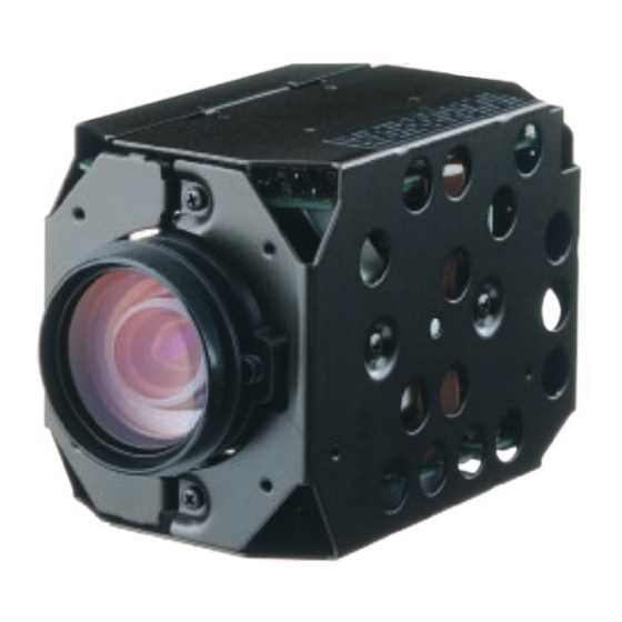
General Description 2-1 Overview VK-S214R/S214ER is a chassis video camera that incorporates an optical 22-power compact zoom lens. The signal process circuit is equipped with a digital signal processor (D.S.P. 3R) that is the same as that of VK-S914/S914E. The external appearance is identical to previous chassis cameras. -
Page 8: Specifications
VK-S914E: 50 Hz Image Sensor 1/4-inch CCD 1/4-inch CCD Total Pixels VK-S214R: 811 (H) × 508 (V), 410k VK-S914: 811 (H) × 508 (V), 410k VK-S214ER: 795 (H) × 596 (V), 470k VK-S914E: 795 (H) × 596 (V), 470k Effective Pixels VK-S214R: 768 (H) ×... -
Page 9: Comparison Of Main Control Ics
2-4 Comparison of Main Control ICs The comparison of main control ICs in shaded columns are different from those of previous models Item VK-S214R/S214ER VK-S914/S914E Image Sensor VK-S214R: ICX228AX (IC1001) VK-S914: ICX208AK (IC1001) VK-S214ER: ICX229AK (IC1001) VK-S914E: ICX209AK (IC1001) Sensor Drive µPD16510GR... -
Page 10: Description Of Operation
Description of Operation 3-1 Structure Schematics 4 - M2 SCREWS for TRIPOD PLATE (These screws are limit of height keep as being less than 2 mm for "A") 50mm 89.5mm 4 - M2 SCREWS 12.5mm 77mm M2 SCREW 25mm 4 - M2 SCREWS for 90˚... -
Page 11: Microprocessor Pin Function Tables
Description of Operation > Microprocessor Pin Function Table 3-2 Microprocessor Pin Function Table 3-2-1 Camera microprocessor (IC1201: Camera µP) Active Abbreviation Function Level (Pulse) LD-DSP Activates data communication with IC1121 (CAMERA DSP). (Pulse) CS-DAC Not used. Open. (Pulse) CS-VAP GYRO-RST ----- CEON -----... - Page 12 Description of Operation > Microprocessor Pin Function Table Active Abbreviation Function Level (Pulse) Receives the vertical sync pulses that detect the iris detection area, from IC1121 (CAMERA DSP). (Pulse) FCUS-SEN Focus motor position detection input. ----- ----- Not used. Open. (Pulse) ZOOM-SEN Zoom motor position detection input.
- Page 13 Description of Operation > Microprocessor Pin Function Table Active Abbreviation Function Level ----- ----- Not used. Open. ----- ----- NC10 ----- ----- NC11 ----- ----- NC12 (Pulse) For data communications with IC1121 (CAMERA DSP), IC1202 (Pulse) (EEPROM). (Pulse) SCLK ----- ----- DC-LIGHT Not used.
-
Page 14: Troubleshooting
Troubleshooting 4-1 Trouble Diagnosis 4-1-1 Setting to service position Remove chassis R and chassis L, referring to “5. Disassembly and Reassembly”, and connect the camera as shown in Fig. 4-1-1. Note: To prevent short-circuit, always perform trouble diagnosis of camera on insulated mat. PC CIRCUIT BOARD SP CIRCUIT... -
Page 15: Trouble Diagnosis Flowchart
Troubleshooting > Trouble Diagnosis 4-1-2 Trouble diagnosis flowchart (1) No video (luminance) signal The test lands and components of circuit no. 1000-1099 are on the SP circuit board. The test lands and components of circuit no. 1100-1499 are TL1530 : 5V Refer to "(3) No power"... - Page 16 Troubleshooting > Trouble Diagnosis TL1082, 1083, IC1121 faulty or connect TL1010 to 1012 : 1085, 1086 : the connections of circuit Pulse Pulse boards.. IC1121 faulty or connect TL1036 to 1039 : the connections of circuit Pulse boards.. IC1002 faulty. TL1004 to 1006 : IC1121 faulty.
- Page 17 Troubleshooting > Trouble Diagnosis The test lands and components of circuit no. 1000-1099 are (3) No power on the SP circuit board. The test lands and components of circuit no. 1100-1499 are on the PC circuit board. The test lands and components of circuit no. 1500 and higher are on the CSR circuit board.
- Page 18 Troubleshooting > Trouble Diagnosis (4) No zoom and focus operation L1301 faulty TL1301:7.2V The test lands and components of circuit no. 1000-1099 are on the SP circuit board. The test lands and components of circuit no. 1100-1499 are on the PC circuit board. Check IC1301 and The test lands and components of circuit no.
- Page 19 Troubleshooting > Trouble Diagnosis C h e c k t h e C o r r e c t t h e c o n n e c t i o n s o f t h e c o n n e c t i o n s l e n s f l a t c a b l e .
- Page 20 Troubleshooting > Trouble Diagnosis (6) No focus lens operation The test lands and components of circuit no. 1000-1099 are on the SP circuit board. The test lands and components of circuit no. 1100-1499 are Does zoom See "(4)No zoom and on the PC circuit board.
- Page 21 Troubleshooting > Trouble Diagnosis ( 7 ) N o z o o m o p e r a t i o n Does focus operate See "(4) No zoom and normally? focus operation." Check the Zoom switch faulty. zoom switch unit. The test lands and components of circuit no.
- Page 22 Troubleshooting > Trouble Diagnosis (8) No auto focus operation Does zoom See "(4) No zoom and operate focus operation." normally? The test lands and components of circuit no. 1000-1099 are on the SP circuit board. Connect an The test lands and components of circuit no. 1100-1499 are on the PC circuit board. oscilloscope The test lands and components of circuit no.
- Page 23 Troubleshooting > Trouble Diagnosis TL1347-TL1350: Lens unit faulty. PULSES IC1302-2,4,24:3V Check the 3V line Check the 7.2V line IC1302-10,15:7.2V IC1302-1 (TL1312): I C 1 3 0 2 f a u l t y . PULSE I C 1 2 0 1 f a u l t y . IC1302-23:PULSE I C 1 2 0 1 f a u l t y .
-
Page 24: Disassembly And Reassembly
Chassis R reverse order to removal unless otherwise specified. 1) and 2) Chassis L Note: When replacing components in the VK-S214R/S214ER, be sure to 3) to 5) PC Circuit Board use only those shown in "Replacement Parts List". 6) and 7) - Page 25 Disassembly and Reassembly > Disassembly PC Circuit Board (Fig. 5-2-2) 3) Disconnect the flat cable from the PC circuit board. To connect flat cables, perform the procedure in Fig. 5-2-3. 4) Remove one screw [B]. 5) Remove the PC circuit board in the direction of the arrow. CSR Circuit Board (Fig.
-
Page 26: Adjustment
Adjustment 6-1 Preparations for Adjustment All adjustments are performed using the adjustment program (ZMAP: Zoom camera Manual Adjustment Program) and personal computer (PC). If error message appears during adjustment, refer to "6-8 Error Messages and Countermeasure". 6-1-1 List of equipment and jigs DSP Interface Connect DSP-R Jig C12 Light Balancing... -
Page 27: Connections For Adjustment
Adjustment > Preparations for Adjustment 6-1-3 Connections for adjustment Connect the video camera to the test equipment and jigs as shown in Fig. 6-1-1 LIGHT VIDEO CAMERA VECTORSCOPE When using a 9PIN FLAT CABLE vectorscope (ACCESSORY) PG1601 INPUT OUTPUT OSCILLOSCOPE DSP INTERFACE CONNECT JIG CH1 CH2 VIDEO... -
Page 28: Setting Test Equipment
Adjustment > Preparations for Adjustment 6-1-4 Setting test equipment (1) Oscilloscope The names of switches, knobs, modes, etc. of oscilloscope may vary slightly depending on the manufacturer or model. Since some oscilloscopes may have switches, etc. other than the above that must be set, see the instruction manual of the particular oscilloscope for details. - Page 29 Adjustment > Preparations for Adjustment 7) The ZMAP will start: Make sure that the model select screen appears on the PC display. (See the model select Model select screen screen) *********************************************************** MODEL SELECT If the model select screen does not appear, make sure of *********************************************************** ××××××××...
-
Page 30: List Of Adjustment Items
Adjustment > List of Adjustment Items 6-2 List of Adjustment Items 6-2-1 List of adjustments needed after replacing major The following table shows the adjustment items, their purposes, and whether or not check is required after replacing major components. The components shown in the table below are the minimum to be checked after replacing major components: If several components have been replaced - or depending on the cause of a defect more components may need to be checked. -
Page 31: Adjustment Flowchart
Adjustment > List of Adjustment Items 6-2-2 Adjustment flowchart Main menu *********************************************************** MANUAL ADJUSTMENT PROGRAM *********************************************************** DATA INITIALIZE ELECTRIC VOLUME ADJUSTMENT AUTO FOCUS SPOT NOISE [ESC] END Please select [A] - [E] or [ESC] Input: A Input: B Input: C Data initialize Electrical volume Adjustment... -
Page 32: Data Initialize
Adjustment > Data Initialize / Electronic Volume 6-3 Data Initialize Restriction: 1) This procedure initializes the adjustment data in EEPROM (including the adjustment data). Any time you replace the EEPROM, be sure to perform this procedure. Generally, this procedure is not necessary after replacing other components. 2) After completing this adjustment, be sure to perform all adjustment items as follows. -
Page 33: Cds Sampling Pulse Adjustment
Adjustment > Electronic Volume / Adjustment (Camera Adjustment) 6-4-1 CDS sampling pulse adjustment Electronic volume menu *********************************************************** Incompleted Phenomenon ELECTRIC VOLUME Diagonal beats and horizontal noise occur. *********************************************************** CDS SAMPLING PULSE Condition: [ESC] RETURN TO MAIN MENU Please select [1] or [ESC] Leave the video camera for more than 2 minutes until the circuits are stabilized after turning it on, then start Input 1. -
Page 34: Auto Iris Control Adjustment
Adjustment > Adjustment (Camera Adjustment) 6-5-1 Auto iris control adjustment Adjustment menu Incompleted Phenomenon *********************************************************** 1) The picture becomes too bright. ADJUSTMENT *********************************************************** 2) The picture becomes too dark. AUTO IRIS CONTROL WHITE BALANCE Condition CHROMA GAIN [ESC] RETURN TO MAIN MENU Set point at the light box, without chart inserted, to fill the Please select [1] - [3] or [ESC] screen. -
Page 35: Chroma Gain Adjustment
5) Press any key to restore the adjustment menu screen. BURST BURST 240% 240% ± 5% ± 5% 686mV ± 20mV 100% 100% Fig. 6-5-1 Chroma Gain Fig. 6-5-3 Chroma Gain Fig. 6-5-2 Chroma Gain (For VK-S214R) (For VK-S214ER) 6 - 10... -
Page 36: Auto Focus
Adjustment > Auto Focus 6-6 Auto Focus Main menu *********************************************************** Input D to PC on the main menu screen to display the AF MANUAL ADJUSTMENT PROGRAM *********************************************************** menu screen. Input the appropriate adjustment number to DATA INITIALIZE PC. Pressing the Esc key on the AF menu screen will restore ELECTRIC VOLUME ADJUSTMENT the main menu screen. -
Page 37: Af Noise Level Adjustment
Adjustment > Auto Focus 6-6-2 AF noise level adjustment AF menu Incompleted Phenomenon *********************************************************** AUTO FOCUS ADJUSTMENT 1) It takes time until a subject is brought into focus. *********************************************************** ADJUSTMENT OF ZOOM/FOCUS TRACKING 2) Correct focus is not obtained. ADJUSTMENT OF AF NOISE LEVEL CHECK OF ZOOM/FOCUS TRACE Condition [ESC] RETURN TO MENU... -
Page 38: Spot Noise
Adjustment > Spot Noise 6-7 Spot Noise Spot noise refers to bright points that appear on the screen, Main menu *********************************************************** which are caused by a defect in pixel of image sensor. MANUAL ADJUSTMENT PROGRAM *********************************************************** DATA INITIALIZE Note: ELECTRIC VOLUME ADJUSTMENT 1) Perform this adjustment after specified components have AUTO FOCUS... -
Page 39: Error Messages And Countermeasure
Adjustment > Error Messages and Countermeasure 6-8 Error Messages and Countermeasure A message may appear while you are adjusting the video camera. If a message appears, refer to the following table and take appropriate corrective action. Error Messages Countermeasure When adjusting the electric volume and adjustment CAN'T ADJUST WHITE BALANCE 1) The subject is too bright or too dark. - Page 40 Adjustment > Error Messages and Countermeasure Error Messages Countermeasure TOO BRIGHT 1) The subject is too bright. PRESS ANY KEY 2) Move the camera further away from the light box. TOO DARK 1) The subject is too dark. PRESS ANY KEY 2) Check the light box.
-
Page 41: Exploded View And Parts List
Exploded View and Parts List 7-1 Exploded View Note: Components without any numbers in exploded views had not been assigned as service parts as of the date of issue of this manual. PC CIRCUIT BOARD [Component Replacement] SP CIRCUIT BOARD [Component Replacement] CSR CIRCUIT BOARD [Component Replacement]... -
Page 42: Replacement Parts List
AA00335R CHIP CERAMIC 1.0UF+80-20% 25V KQ10752 LENS ASSY C1003 AA00335R CHIP CERAMIC 1.0UF+80-20% 25V NX11252 RUBBER C1004 AA00422R CERAMIC CHIP 10UF 16V UE15891 SENSOR ASSY [VK-S214R] C1005 AA00422R CERAMIC CHIP 10UF 16V UE15892 SENSOR ASSY [VK-S214ER] C1006 0893193 CERAMIC CHIP 0.01UF+-10% 25V DT10251 TUBE,CAMERA... - Page 43 0893008 CERAMIC CHIP 0.1UF +-10% 16V R1151 0790001 JUMPER CHIP RESISTOR C1509 AA00422R CERAMIC CHIP 10UF 16V R1153 AQ00176R CHIP RESISTOR 220 OHM+-1% 1/16W [VK-S214R] C1511 0893008 CERAMIC CHIP 0.1UF +-10% 16V R1153 0790001 JUMPER CHIP RESISTOR [VK-S214ER] C1513 0893202...
- Page 44 SYMBOL SYMBOL P-NO DESCRIPTION P-NO DESCRIPTION R1171 0790077 CHIP RESISTOR 1MOHM+-5% 1/16W R1371 0790029 CHIP RESISTOR 270 OHM+-5% 1/16W R1172 0790035 CHIP RESISTOR 680 OHM+-5% 1/16W R1372 0790046 CHIP RESISTOR 4.7KOHM+-5% 1/16W R1173 0790051 CHIP RESISTOR 10KOHM+-5% 1/16W R1374 0790049 CHIP RESISTOR 8.2KOHM+-5% 1/16W R1175 0790059...
- Page 45 BA10584R COIL 100UH IC1002 CK12061R IC UPD16510GR IC1101 CK21332U IC HD49323AF CRYSTALS IC1121 CK20631U IC HG73C012TE IC1173 CK15051R IC TC7SU04FU X1171 BL11096R CRYSTAL [VK-S214R] IC1174 CK18421R IC TC7SHU04FU X1171 BL11097R CRYSTAL [VK-S214ER] IC1175 CK27241R IC SN74VLC00APW X1172 BL11098R CRYSTAL IC1176...
-
Page 46: Schematic, Circuit Board And Block Diagrams
Schematic, Circuit Board and Block Diagrams 1 Wiring Diagram PG1301 PG1241 LENS UNIT PG1001 PG1002 PG1501 PG1601 OUTPUT - 1 - - 1 -... -
Page 47: Schematic Diagrams
12.0 -5.0 -5.0 -5.0 IC1001 ICX228AK-K[S214R] ICX229AK-K[S214ER] IMAGE SENSOR 25.0 -5.0 10.0 12.0 -5.0 -5.0 PROCESS [PC] PG1241 CODE PART NAME VK-S214R VK-S214ER IC1001 ICX228AK-K ICX229AK-K 2SC2620-QC 1SS353 VOLTAGE: REC MODE SENSOR [SP] SWITCH REG [CSR] PG1501 - 2 -... -
Page 48: Process [Pc] Schematic Diagram (For Display)
A/D CONV CAMERA DSP LENSE UNIT SENSOR [SP] PG1001 CLOCK GEN. ZOOM MOTOR DRIVE ZOOM MOTOR DRIVE CLOCK SELECT INV. 28.6M[S214R] CLOCK GEN. 28.5M[S214ER] VK-S214R VK-S214ER X1171 28.6MHz 28.5MHz R1153 HD6432237M15TE CAMERA µP CODE PART NAME 2SB1462 2SC2412K 2SC2411K TC7S08FU F.DET/IRIS DRIVE... -
Page 49: Process [Pc] Schematic Diagram
2-3 Process [PC] Schematic Diagram (For Printing) - 4 -... -
Page 50: Process [Pc] Schematic Diagram
2-4 Process [PC] Schematic Diagram (For Printing) - 5 -... - Page 51 2-5 Switch Reg [CSR] Schematic Diagram Y/C MIX & VIDEO AMP TC7S08 VCO/PHASE COMPA. LEVEL SHIFT C1607 22p[S214R] 12p[S214ER] OUTPUT CODE PART NAME VK-S214R VK-S214ER C1607 2SB1424 2SB1462 2SC4081 2SC4617 2SC2620-QC (AE) DTA143EE DTC144EE DTC114YE XP4401 1SS353 SB07-03C (AE) MA132WA...
-
Page 52: Circuit Board Diagram
3-1 PC Circuit Board Diagram TL1301 TL1311 TL1312 TL1349 TL1346 TL1336 TL1345 TL1335 TL1344 TL1348 TL1347 TL1350 TL1333 TL1332 TL1334 TL1331 BLM11B750SPT VK-S214R VK-S214ER PC -SIDE A- PC -SIDE B- VK-S214R VK-S214ER R1153 X1171 28.6MHz 28.5MHz [PATTERN No.JA2065-2] [PATTERN No.JA2065-2] - 7 -... -
Page 53: Sp Circuit Board Diagram
3-2 SP Circuit Board Diagram 3-3 CSR Circuit Board Diagram BV10201R SP -SIDE A- CSR -SIDE A- VK-S214R VK-S214ER [PATTERN No.JA2065-2] C1607 [PATTERN No.JA2065-2] TL1525 TL1609 TL1004 TL1005 TL1085 TL1008 FLC800Z16SMMZ TL1006 TL1036 TL1010 TL1528 TL1082 TL1086 TL1083 120k TL1533... -
Page 54: Identification Parts Location
3-4 Identification of Parts Location Symbol Parts Symbol Parts Symbol Parts Symbol Parts Symbol Parts Symbol Parts Symbol Parts Symbol Parts Symbol Parts Location Location Location Location Location Location Location Location Location C1184 A-1B IC1202 A-3C R1182 B-1A R1375 A-1D D1503 B-1A R1518... -
Page 55: Block Diagrams
4. Block Diagrams 4-1 Overall Block Diagram IC1121 CAMERA DSP TYPE R TYPE ER IC1101 22pF 12pF IC1001 C1607 PG1001 PG1241 CDS/AGC & A/D CONV IMAGE 3.58MHz 4.43MHz Q1001 (1/2) (1/2) SENSOR BUF. Y/CHROMA 2-11 91-100 DIGITAL PROCESS AUTO FOCUS IC1601 12-14 DET. -
Page 56: Power Block Diagram
4-2 Powe Block Diagram IC1502 IC1301 PG1501 PG1002 PG1001 PG1241 PG1601 CP1601 7.2V 7.2V 7.2V F1601 L1301 23,24 23,24 7.2V 10,15 ZOOM D1507 MOTOR 2,4,24 DRIVE L1507 IC1302 10,15 FOCUS Q1502 MOTOR IC1501 L1502 2,4,24 DRIVE IC1601 IC1351 L1601 13,16 L1202 Y/C MIX &... - Page 57 VK-S214R TK No. 8301E Digital Media Division,Tokai VK-S214ER Copyright © Hitachi, Ltd. 2003. All rights reserved. Printed in Japan (I)