
Related Manuals for Epson RC700-D


Summary of Contents for Epson RC700-D
- Page 1 ROBOT CONTROLLER RC700-D Manual Rev.2 EM221C5146F Control Unit RC700-D Original instructions...
- Page 3 ROBOT CONTROLLER RC700-D Manual Rev.2 Copyright © 2021-2022 SEIKO EPSON CORPORATION. All rights reserved. RC700-D Rev.2...
- Page 4 Please notify us if you should find any errors in this manual or if you have any comments regarding its contents. MANUFACTURER CONTACT INFORMATION Contact information is described in “SUPPLIERS” in the first pages of the following manual: Robot System Safety Manual Read this manual first RC700-D Rev.2...
- Page 5 For more details on available collection facilities please contact your local government office or the retailer where you purchased this product. For California customers only The lithium batteries in this product contain Perchlorate Material - special handling may apply, See www.dtsc.ca.gov/hazardouswaste/perchlorate RC700-D Rev.2...
- Page 6 Before Reading This Manual NOTE Do not connect the followings to the TP port of RC700-D. Connecting to the followings may result in malfunction of the device since the pin assignments are different. OPTIONAL DEVICE dummy plug Operation Pendant OP500...
- Page 7 EPSON RC+ 7.0 User’s Guide (PDF) This manual describes general information about program development software. EPSON RC+ 7.0 SPEL+ Language Reference (PDF) This manual describes the robot programming language “SPEL+”. Other Manual (PDF) Manuals for each option are available.
- Page 8 RC700-D Rev.2...
-
Page 9: Table Of Contents
2.6.10 Resetting the Safeguard ............24 2.6.11 Robot Operation Panel.............. 24 2.7 Connecting ....................25 2.7.1 Connection to EMERGENCY Connector ........25 2.7.2 Power Supply ................32 2.7.3 Connecting Manipulator and Controller ........34 2.8 Saving Default Status ................34 RC700-D Rev.2... - Page 10 3.1 Power-ON Precautions ................35 3.2 Power ON Procedure ................36 4. First Step 4.1 Installing EPSON RC+ 7.0 Software ............37 4.2 Development PC and Controller Connection ......... 39 4.2.1 About Development PC Connection USB Port ......40 4.2.2 Precaution ................... 40 4.2.3 Software Setup and Connection Check ........
- Page 11 4.2 Switch Operation Mode ................93 4.3 Program Mode (AUTO) ................94 4.3.1 What is Program Mode (AUTO)? ..........94 4.3.2 Setup from EPSON RC+ ............. 94 4.4 Auto Mode (AUTO) ................. 95 4.4.1 What is Auto mode (AUTO)? ............95 4.4.2 Setup from EPSON RC+ .............
- Page 12 6.2.2 Adoptable USB Memory ............100 6.3 Backup Controller Function ..............101 6.3.1 Backup Controller with Trigger Button ........101 6.3.2 Load Data with EPSON RC+ 7.0 ..........101 6.3.3 Transfer with E-mail ..............101 6.4 Details of Data ..................102 7.
- Page 13 9.4.2 Example 2: External safety relay typical application ....115 10. Standard RS-232C Port 10.1 RS-232C Port ..................116 10.2 Confirmation with EPSON RC+ 7.0 (RS-232C) ......... 116 10.3 RS-232C Software Communication Setup (RS-232C)....... 117 10.4 Communication Cable (RS-232C) ............117 11.
- Page 14 14.2 Expansion I/O Board ................137 14.2.1 Expansion I/O Board ............... 137 14.2.2 Board Configuration (Expansion I/O Board) ......138 14.2.3 Confirmation with EPSON RC+ 7.0 (Expansion I/O Board) ... 138 14.2.4 Input Circuit ................139 14.2.5 Output Circuit ................141 14.2.6 Pin Assignments (Expansion I/O Board) ........
- Page 15 Table of Contents 14.8.11 Emergency stop connecter Pin Assignments (EUROMAP67 Board) .............. 171 Regular Inspection 1. Regular Inspection for RC700-D 1.1 Inspections and Schedules ..............175 2. Backup and Restore 2.1 What is the Backup Controller Function? ..........176 2.2 Backup Data Types ................176 2.3 Backup ....................
- Page 16 Table of Contents RC700-D Rev.2...
-
Page 17: Installation
Installation This section describes outline from unpacking to operation of Robot System and design of Robot System. -
Page 19: Safety
WARNING not followed properly. This symbol indicates that a danger of possible harm to people or physical damage to equipment and facilities exists if the associated CAUTION instructions are not followed properly. RC700-D Rev.2... -
Page 20: Installation
Windows 8.1 Pro (EPSON RC+ 7.0 Ver.7.1.0 or later) Windows 10 Pro (EPSON RC+ 7.0 Ver.7.2.0 or later) *2 Any one of the Teach pendant can be controlled. *3 When connecting to RC700-D, a dedicated conversion cable is required. RC700-D Rev.2... -
Page 21: Unpacking
: Under the arm 1 and bottom of the base *(shade part) * When hold bottom of the base, be careful not caught your hands or fingers. Minimum number of people : 2 people Do not hold Table Top Mounting Multiple Mounting RC700-D Rev.2... - Page 22 : Under the arm 1 and bottom of the base *(shade part) * When hold bottom of the base, be careful not caught your hands or fingers. Minimum number of people : 2 people Do not hold Wall Mounting Table Top Mounting Ceiling Mounting RC700-D Rev.2...
-
Page 23: Manipulator Installation
When using Manipulators in inadequate environments that do not meet the above conditions, please contact the supplier of your region. - If there are conductive things such as fences or ladders within 2.5 m of the Manipulator, ground the things. RC700-D Rev.2... -
Page 24: Noise Level
Use the mounting bolts conforming to the strength of ISO898-1 property class 10.9 or 12.9. The plate for the Manipulator mounting face should be 20 mm thick or more and made of steel to reduce vibration. The surface roughness of the steel plate should be 25 μm or less. RC700-D Rev.2... - Page 25 Manipulator does not fall over. (3) Wipe off the dust on the Manipulator with a little alcohol or distilled water on a lint- free cloth. (4) Transport the Manipulator into the cleanroom. (5) Secure the Manipulator to the base table. RC700-D Rev.2...
-
Page 26: Installation Procedure
4×M8 screw hole (depth: 20 mm or more) For cable downward: NOTE Be sure to allow spaces for the center of the table to mount the base. Length: 190mm or more Width: 104mm Depth: 190mm or more RC700-D Rev.2... - Page 27 4×M8 Screw Hole (depth 20mm or Make sure to use the washer. more) NOTE Use bolts with specifications conforming to ISO898-1 Property Class: 10.9 or 12.9. Tightening torque: 32.0 N·m (326 kgf·cm) Pane washer Spring washer 4×M8×30 RC700-D Rev.2...
- Page 28 Be sure to allow spaces for the center of the table to mount the base. Diameter: ø150mm or more Diameter: Depth: M/C cable (L-shaped) ø150mm or more 120mm or more Depth: M/C cable (straight) 120mm or more 190mm more RC700-D Rev.2...
- Page 29 6×M8 Screw hole (depth 20 mm or NOTE Use bolts with specifications conforming to more) ISO898-1 Property Class: 10.9 or 12.9. Tightening torque: 32.0 N·m (326 kgf·cm) 6×Pane washer (3) Remove the shipping bolt and jigs. 6×Spring washer 6×M8×40 RC700-D Rev.2...
- Page 30 Use bolts with specifications conforming to or more) Pane washer ISO898-1 Property Class: 10.9 or 12.9. Spring Tightening torque: washer M8 : 32.0 N·m (326 kgf·cm) 4×M8×40 M10 : 58.0 N·m (592 kgf·cm) (3) Remove the shipping bolt and jigs. RC700-D Rev.2...
-
Page 31: Control Unit Installation
- Keep away from dust, oily mist, oil, salinity, metal powder or other contaminants. - Keep away from water. - Keep away from shocks or vibrations. - Keep away from sources of electronic noise - Keep away from strong electric or magnetic fields. RC700-D Rev.2... -
Page 32: Installation
Remove the screws that interfere the rubber foot. (C) Rack mounting * A plate for rack mounting is required. NOTE For Controller installation to the Controller box or the base table, process screw hole drilling as follows. RC700-D Rev.2... - Page 33 - Hot air with higher temperature than the ambient temperature (about 10 °C) comes out from the Controller. Make sure that heat sensitive devices are not placed near the outlet. - Arrange the cables in front of the Controller so that you can pull the Controller forward. RC700-D Rev.2...
-
Page 34: Wall Mounting Option
* Keep the space about 200 mm or more on the top to maintenance. Wall mounting with the front side down Wall mounting with the front side up 100 mm 200 mm 50 mm * 50 mm 50 mm 50 mm * 50 mm 50 mm 200 mm 100 mm RC700-D Rev.2... -
Page 35: Designing A Safe Robot System
This section summarizes the minimum conditions that should be observed when using EPSON robots in your robot systems. Please design and manufacture robot systems in accordance with the principles described in this and the following sections. -
Page 36: Disabling Power To The System Using Lock Out / Tag Out
I/O. To prevent danger from unintended remote control, the remote function will not be enabled without proper settings. Also when remote is valid, motion command execution and I/O output are available only from remote. RC700-D Rev.2... -
Page 37: Emergency Stop
To place the robot system in emergency mode during normal operation, press the Emergency Stop switch while the Manipulator is not moving. Refer to the Controller manual for instructions on how to wire the Emergency Stop switch circuit. RC700-D Rev.2... -
Page 38: Safeguard
Carefully consider the size of the end effector and the work pieces to be held so that there will be no error between the moving parts and the safeguard system. Manufacture the safeguard system to withstand calculated external forces (forces that will RC700-D Rev.2... - Page 39 For details of the safeguard, refer to the following manuals as well. 2.7.1 Connection to EMERGENCY Connector Free running distance when the safeguard is opened The Manipulator in operation cannot stop immediately after the safeguard is opened. In RC700-D Rev.2...
-
Page 40: Presence Sensing Device
The robot will never restart simply by resetting the safeguard interlock switch. Apply this concept to the interlock gates and presence sensing devices for the entire system. 2.6.11 Robot Operation Panel Ensure that the robot system can be operated from outside of the safeguard. RC700-D Rev.2... -
Page 41: Connecting
The EMERGENCY connector has input terminals for the Safety Door switch and the Emergency Stop switch. Be sure to use these input terminals to keep the system safe. Connector Standard EMERGENCY connector D-sub25 Pin (male) (Controller side) Screwlock #4-40 RC700-D Rev.2... - Page 42 When the latched TEACH mode is released while the safety door is open, the status of NOTE Manipulator power is operation-prohibited because the safety door is open at that time. To execute a Manipulator operation, close the safety door again, and then close the latch release input. RC700-D Rev.2...
- Page 43 (1) Turn ON the Controller while the safety door is open in order to boot the Controller software. (2) Make sure that “Safety” is displayed on the EPSON RC+ 7.0 status bar. (3) Close the safety door, and turn ON the switch connecting to the latch release input.
- Page 44 Stop switch. (2) Make sure that the seven-segment LED on the Controller displays (3) Make sure that “EStop” is displayed on the EPSON RC+ 7.0 status bar. (4) Release the Emergency Stop Switch. (5) Select EPSON RC+ 7.0-[Tools]-[Robot Manager]-[Control Panel] and click the <Reset>...
- Page 45 The 24 V output is for emergency stop. Do not use it for other purposes. Doing so may result in system malfunction. ■ Do not apply reverse voltage to the Emergency Stop circuit. CAUTION Doing so may result in system malfunction. RC700-D Rev.2...
- Page 46 IF circuit External AC Input Safety Door input 1 IF circuit Safety Door input 2 IF circuit Latch release input IF circuit External Latch release input +24V NOTE:+24V GND Close: Latch off + 5V GND Open: Latch on RC700-D Rev.2...
- Page 47 IF Circuit External +24V NOTE:+24V GND Latch release input + 5V GND Close: Latch off Open: Latch on * To protect Emergency Stop Circuit, use the fuse that is 0.4A or under and matches amount of external safety relay. RC700-D Rev.2...
-
Page 48: Power Supply
10 kHz or more leakage current. If you install a circuit breaker, please select one that will handle the above mentioned “peak current”. The power receptacle should be installed near the equipment and should be easily accessible. RC700-D Rev.2... - Page 49 Following shows specification of power connection side. Mount to the plug like following below. Item Specification AC power wire Black, Black (2 cables) Ground wire Green / Yellow Cable length M4 round solderless Terminal terminal RC700-D Rev.2...
-
Page 50: Connecting Manipulator And Controller
The Controller is already setup with the purchased robot(s) at shipment. However, just in case, we recommend saving the default Controller status. A USB memory is necessary to save the Controller status. For the procedure of Controller status storage, refer to Robot Controller: 8. Memory Port. RC700-D Rev.2... -
Page 51: Power-On
Manipulator. When supplying the power to the Controller again, turn OFF the When supplying Controller and wait for 5 seconds or more. Then, turn ON the the power again Controller again. RC700-D Rev.2... -
Page 52: Power On Procedure
30 seconds after Controller starts up normally. If an error is displayed, check connection in step (1) to (5) and turn ON the power again. If an error is displayed after checking the connection, contact the supplier in your region. RC700-D Rev.2... -
Page 53: First Step
Installation 4. First Step 4. First Step This section indicates the procedure to install the development PC EPSON RC+, and execute simple program after connecting the development PC and Controller with a USB. Make sure that the Robot system is installed safely by following the description in “Safety”... - Page 54 Installation 4. First Step (4) Select the drive where you want to install EPSON RC+ 7.0 and click <Next>. The installation directory is called EpsonRC70. This cannot be changed. (5) The dialog box for selecting the options to be installed will be displayed. Check the options you want to install and click <Next>.
-
Page 55: Development Pc And Controller Connection
Installation 4. First Step (7) “Windows Installer” will be installed. This may takes several minutes. Adobe Reader needs to be installed on your PC in order to view the EPSON RC+ 7.0 NOTE manuals. If the installer cannot find Adobe Reader on your system, it will be installed at this time. -
Page 56: About Development Pc Connection Usb Port
(USB Ver.1.1 upward compatible) Connect the Controller and development PC by a USB cable to develop the robot system or set the Controller configuration with the EPSON RC+ 7.0 software installed in the development PC. Development PC connection port supports hot plugging. Insertion and removal of the cables while the power of the development PC and the Controller are ON is available. -
Page 57: Software Setup And Connection Check
4.2.3 Software Setup and Connection Check The following is the steps of connecting the development PC and the Controller. (1) Make sure that EPSON RC+ 7.0 is installed on the Controller connected to the development PC. (Install the software when it is not installed.) (2) Connect the development PC and the Controller by the USB cable. -
Page 58: Backup The Initial Condition Of The Controller
4.2.5 Disconnection of Development PC and Controller Disconnection of the development PC and the Controller is indicated. (1) Select the EPSON RC+ 7.0 menu-[Setup]-[PC to Controller Communications] to display the [PC to Controller Communications] dialog box. (2) Click the <Disconnect> button. - Page 59 The arm falling may cause equipment damage to and/or malfunction of the Manipulator. (1) Start the EPSON RC+ 7.0. Double click the <EPSON RC+ 7.0> icon on the desktop. (2) Open the command window. EPSON RC+ 7.0 menu-[Tool]-[Command Window] (3) Execute the following command in [Command Window].
- Page 60 Following explains the example of moving all joints to the 0 pulse positions by specifying the pulse for each joint. (1) Start EPSON RC+ 7.0. Double click the <EPSON RC+ 7.0> icon on the desktop. (2) Open the command window. EPSON RC+ 7.0 menu-[Tools]-[Command Window] (3) Execute the following command in [Command Window].
- Page 61 (1) Start EPSON RC+ 7.0. Double click the <EPSON RC+ 7.0> icon on the desktop. (2) Create a new project. 1. EPSON RC+ 7.0 menu-[Project]-[New Project]. [New Project] dialog box will be displayed. 2. Enter the project name in [Project Name] box. (Ex: FirstApp) 3.
- Page 62 (5) Move the Manipulator with Jog motion. Select [Jog & Teach] tab. Select “Joint” in [Jogging]-<Mode>. Move the Manipulator by joint by clicking J1-J4 jog keys. Manipulator can be moved by setting to other modes or setting the jog distance. RC700-D Rev.2...
-
Page 63: Writing Your First Program
Installation 4. First Step 4.3 Writing your first program After installing the Controller, Manipulator, and EPSON RC+ 7.0 software on your PC, follow the instructions below to create a simple application program so that you will become more familiar with EPSON RC+ 7.0 development environment. - Page 64 (3) Click the Start button on the Run window to run the program. (4) The texts like the following will be displayed in the status window. 19:32:45 Task main started 19:32:45 All tasks stopped On the Run window, you will see the output of the print statement. RC700-D Rev.2...
- Page 65 Move the robot until it reaches the middle of the work envelope. (7) Click the <-Z> button to lower the Z axis of the robot. (8) Select “P1” in the [Point (P)] dropdown list which is next to the <Teach> button. The current point is set to P1. RC700-D Rev.2...
- Page 66 (3) Click the <Start> button to execute the program. (4) The robot will move to each of the points you taught at 20% speed, acceleration, and deceleration. The Power High statement executes the program to operate the robot with increased speed and acceleration. RC700-D Rev.2...
- Page 67 Even though this is only a sample project, we will backup the project and Controller configuration. Backup can be done easily with EPSON RC+ 7.0. It is important that you keep regular backups of your applications on an external media such as a USB memory key.
-
Page 68: Firmware Update
Controller firmware is supplied by CD-ROM as needed. Please contact the supplier of your region for information. You must use a PC running EPSON RC+ 7.0 connected to a Controller with USB to update the Controller firmware. Firmware cannot be updated with an Ethernet connection. - Page 69 <Install> button. (8) The firmware upgrade starts. It takes several minutes to complete. Do not disconnect the USB cable during transfer or turn OFF the Controller or the NOTE development PC. (9) Continuous data file transfer starts. RC700-D Rev.2...
- Page 70 The firmware upgrade is complete. When you install the firmware (Ver.7.4.0.2 or later) on the Controller which the firmware NOTE (before Ver.7.4.0.2) has been installed, the following message is displayed. When the message is displayed, re-install the firmware. RC700-D Rev.2...
-
Page 71: Controller Recovery
30 seconds. This will cause the Controller to start in Recovery mode. (3) Make sure that the LED of ERROR, TEACH, and PROGRAM are lighting. (4) Follow the procedure in 4.4.4 Firmware Initialization Procedure from step (3) to initialize the firmware. RC700-D Rev.2... -
Page 72: Firmware Initialization Procedure
(1) Connect the development PC to the Controller with a USB cable (the firmware cannot be changed with an Ethernet connection). (2) Turn ON the Controller. Do not start the development software EPSON RC+ 7.0 until firmware initialization is complete. - Page 73 (9) The following dialog appears after the Controller reboot. Click the <Finish> button. The firmware upgrade is completed. Start EPSON RC+ 7.0 and restore the Controller settings. For details of restoring the operating system, refer to Regular Inspection 2. Backup and Restore.
-
Page 74: Adding Confirmation Steps By Strengthening Security Of Ethernet
Controller IP address is set to global IP address Firmware version is 7.4.8.x or later EPSON RC+7.0 is Ver.7.4.7 or before When the Controller firmware is updated under the following conditions, additional steps to confirm whether to continue the firmware update may be execute depending on the configuration settings of the Controller. - Page 75 When the <OK> button is clicked, Step3 window is displayed. Go to the step (6). When the <Cancel> button is clicked, Step3 window is displayed. The [Disable connection password] checkbox and the <Install> button will be grayed out and cannot be selected. RC700-D Rev.2...
- Page 76 When the <OK> button is clicked, Step 4 window is displayed. Go to the step (7). When the <Cancel> button is clicked, the window is closed. (7) Firmware installation starts. When the firmware is installed, click the <Next> button. Reboot the Controller. RC700-D Rev.2...
- Page 77 Installation 4. First Step (8) When the Controller is rebooted, the following window is displayed. Confirm that the firmware is installed. Click the <Finish> button. RC700-D Rev.2...
-
Page 78: Second Step
This section shows the manuals which contains information of necessary settings and setting procedure. 5.1 Connection with External Equipment 5.1.1 Remote Control EPSON RC+ 7.0 User’s Guide “12. Remote Control” Functions “12.1 Remote I/O” EPSON RC+ 7.0 User’s Guide “11. I/O Setup” Functions “11. I/O Connector” “14.2 Expansion I/O Board”... -
Page 79: Ethernet Connection Of Development Pc And Controller
Installation 5. Second Step 5.2 Ethernet Connection of Development PC and Controller EPSON RC+ 7.0 User’s Guide “1.9 Security for Controller Ethernet Connection” “1.10 Security for Compact Vision CV2-A Ethernet Connection” “1.11 Security for Feeder Ethernet Connection ” “4.3.3 Ethernet Communication ”... - Page 80 Installation 5. Second Step RC700-D Rev.2...
-
Page 81: Functions Required For Designing
Functions required for designing This section contains information for setup and operation of the Robot Controller. -
Page 83: Specifications
Windows 8.1 Pro (EPSON RC+ 7.0 Ver.7.1.0 or later) Windows 10 Pro (EPSON RC+ 7.0 Ver.7.2.0 or later) *2 Any one of the Teach pendant can be controlled. *3 When connecting to RC700-D, a dedicated conversion cable is required. RC700-D Rev.2... -
Page 84: Standard Specifications
Functions 1. Specifications 1.2 Standard Specifications Item Specification Model Robot Controller RC700-D 32 bits Micro Processor Controllable axes AC servo motors 4 joints Programming language and EPSON RC+ 7.0 Robot control (a multi-tasking robot language) software Up to 4 joints simultaneous control... - Page 85 Also, make sure to keep your hands, fingers, and feet safe from being caught or serious injury. *2 When using the Force Sensor I/F board, a maximum of one board/two ports expansion is available for RS-232C board. RC700-D Rev.2...
- Page 86 Functions 1. Specifications NOTE Use this product under the condition of overvoltage category 2, degree of stain category 2. RC700-D Rev.2...
-
Page 87: Outer Dimensions
Functions 1. Specifications 1.3 Outer Dimensions [Unit: mm] RC700-D Rev.2... -
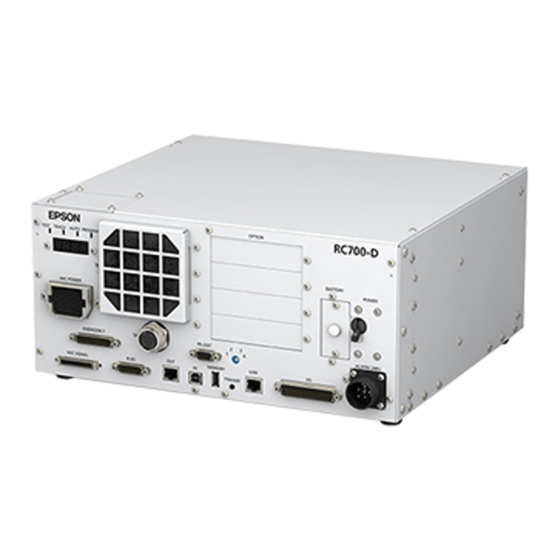
Page 88: Part Names And Functions
Analog I/O board, and Force Sensor I/F board can be installed. Four slots are available. For details, refer to 14. Option Slots. (7) Battery A lithium battery for data backup. (8) POWER switch Turns ON or OFF the Controller. RC700-D Rev.2... - Page 89 Connects Teach Pendant TP2, TP3 (Option) and TP bypass plug. For details, refer to 8. TP Port. NOTE Do not connect the following to the TP port of RC700-D. It may result in malfunction of the device since the pin assignments are different.
- Page 90 This connector is used for input/output device. There are 24 inputs and 16 outputs. For details, refer to Setup & Operation 11. I/O Connector. (22) AC IN The connector for 200VAC power input. For details, refer to 3.3.2 AC Power Cable. RC700-D Rev.2...
-
Page 91: Led And Seven-Segment Led
*1 For error numbers, refer to Status Code / Error Code List or Online Help. *2 In initial status, execution line of task number 1 is displayed in three-digit. Use Ton statement to change the displayed task number. For details, refer to EPSON RC+ 7.0 SPEL+ Language Reference, or Online Help. RC700-D Rev.2... -
Page 92: Particular Status Display
Indicate:9998 AC power supply drop is detected and software shut down. Indicate:9997 Software shut down is specified from the EPSON RC+ 7.0 (software) or the Teach Pendant (option). *1 When the Initialize Error occurs, reboot the Controller. If the Initialize Error is displayed again after the Controller is rebooted, please contact the supplier of your region. -
Page 93: Protection Features
CPU and the motor controlling CPU inside the Drive Unit are also designed to constantly check each other for any discrepancies. If a discrepancy is detected, the dynamic brake circuit is activated. Memory Check-sum Error Detection The dynamic brake circuit is activated when a memory check-sum error is detected. RC700-D Rev.2... - Page 94 AC Power Supply Voltage Drop Detection The dynamic brake circuit is activated when the drop of the power supply voltage is detected. Temperature Anomaly Detection The temperature anomaly is detected. Fan Malfunction Detection Malfunction of the fan rotation speed is detected. RC700-D Rev.2...
-
Page 95: Installation
Use a base table that is at least 100 mm off the floor. Placing the Controller directly on the floor could allow dust penetration leading to malfunction. Tilt 0.5° or less Install surface (When installing upright, you put your hand on it, it may fall over.) RC700-D Rev.2... -
Page 96: Installation
Remove the screws that interfere the rubber foot. (C) Rack Mounting * A plate for rack mounting is required. NOTE or Controller installation to the Controller box or the base table, process screw holes as follows. RC700-D Rev.2... - Page 97 Ensure the air flow around the supply and exhaust ports, and install the Controller while leaving space from other equipment or walls as below. * Keep the space about 200 mm or more on the top to maintenance. RC700-D Rev.2...
- Page 98 - Hot air with higher temperature than the ambient temperature (about 10 °C) comes out from the Controller. Make sure that heat sensitive devices are not placed near the outlet. - Arrange the cables in front of the Controller so that you can pull the Controller forward. RC700-D Rev.2...
-
Page 99: Wall Mounting Option
* Keep the space about 200 mm or more on the top to maintenance. Wall mounting with the front side down Wall mounting with the front side up 100 mm 200 mm 50 mm * 50 mm 50 mm 50 mm * 50 mm 50 mm 200 mm 100 mm RC700-D Rev.2... -
Page 100: Power Supply
10 kHz or more leakage current. If you install a circuit breaker, please select one that will handle the above mentioned “peak current”. The power receptacle shall be installed near the equipment and shall be easily accessible. RC700-D Rev.2... -
Page 101: Ac Power Cable
Following shows specification of power connection side. Mount to the plug like following below. Item Specification AC power wire Black, Black (2 cables) Ground wire Green / Yellow Cable length M4 round solderless Terminal terminal RC700-D Rev.2... -
Page 102: Cable Connection
Manipulator may cause not only improper function of the robot system but also safety problems. CAUTION Before connecting the connector, make sure that the pins are not bent. Connecting with the pins bent may damage the connector and result in malfunction of the robot system. RC700-D Rev.2... -
Page 103: Typical Cable Connection
Connect the Manipulator and the M/C SIGNAL connector on the Controller. (4) EMERGENCY The EMERGENCY connector has inputs to connect the Emergency Stop switch and the Safety Door switch. For safety reasons, connect proper switches for these input devices. For details, refer to the 9. EMERGENCY. RC700-D Rev.2... - Page 104 This connector is used for connecting with input signals necessary for real time I/O function. For details, refer to the 13. R-I/O Connector. (12) Fieldbus I/O If necessary, take EMC countermeasures for the Fieldbus I/O cable. For details, refer to 3.5 Noise Countermeasures. RC700-D Rev.2...
-
Page 105: Connecting Manipulator To Controller
Therefore, the Controller should be connected to the Manipulator whose serial number is specified in the Connection Check label attached on the front of the Controller. NOTE The Manipulator’s serial number is indicated on the signature label on the back of the Manipulator. RC700-D Rev.2... -
Page 106: Noise Countermeasures
The spark suppressor is more effective when placed closer to the motor. - As they are easily influenced by noise, keep cable such as USB, Ethernet, RS-232C, or fieldbus away from peripheral noise sources. RC700-D Rev.2... - Page 107 - Put together the cable shield side. Remove the outer cover and fix with the FG clamp. Secure the clamps to the Controller with screws to ground the shield. - Mount Ferrite core to the cable. Ferrite core RC700-D Rev.2...
-
Page 108: Operation Mode (Teach/Auto/Test)
To use a low speed program verification function (T1: manual deceleration mode) or a NOTE high speed program verification function (T2: manual deceleration mode) which is defined in Safety Standards, you will need a Teach Pendant that supported for the function. RC700-D Rev.2... -
Page 109: Switch Operation Mode
If you switch the mode with the mode selector key switch and turn on the motor while the enable switch is ON, an error will occur. Turn the Enable Switch off and then on again, and then turn on the motor. RC700-D Rev.2... -
Page 110: Program Mode (Auto)
Follow the procedures below to switch to the Program mode. 4.3.2 Setup from EPSON RC+ Switch the mode to Program mode from the EPSON RC+. (1) Select EPSON RC+ menu-[Setup]-[System Configuration] to display the [System Configuration] dialog. (2) Select [Startup]-[Start mode]. -
Page 111: Auto Mode (Auto)
Auto mode (AUTO) is for automatic operation of the Robot system. Procedures for switching to the Auto mode (AUTO) are the followings. A : Set the start mode of the EPSON RC+ to “Auto” and start the EPSON RC+. (Refer to 4.4.2 Setup from EPSON RC+.) B : Offline the EPSON RC+. -
Page 112: Setup From Control Device
Functions 4. Operation Mode (TEACH/AUTO/TEST) 4.4.3 Setup from Control Device Set the control device from EPSON RC+. (1) Select EPSON RC+ menu-[Setup]-[System Configuration] to display the [System Configuration] dialog. (2) Select [Controller]-[Configuration]. (3) Select [Setup Controller]-[Control Device] to select the control device from the following two types. -
Page 113: Development Pc Connection Usb Port
7.0 User’s Guide 5.12.1 PC to Controller Communications Command. For RC700-D, be sure to install the EPSON RC+ 7.0 to the development PC first, then connect the development PC and RC700-D with the USB cable. If RC700-D and the development PC are connected without installing the EPSON RC+ 7.0 to the development PC, [Add New Hardware Wizard] appears. -
Page 114: Precaution
Development PC Connection USB Port Connection of the development PC and the Controller is indicated. (1) Make sure that software EPSON RC+ 7.0 is installed to the Controller connected to the development PC. (Install the software when it is not installed.) (2) Connect the development PC and the Controller using a USB cable. -
Page 115: Disconnection Of Development Pc And Controller
5.4 Disconnection of Development PC and Controller This section describes how to disconnect the development PC and the Controller communication. (1) Select the EPSON RC+ 7.0 menu-[Setup]-[PC to Controller Communications] to display the [PC to Controller Communications] dialog. (2) Click the <Disconnect> button. -
Page 116: Memory Port
This function saves various kinds of Controller data to the USB memory with one push. Data saved in the USB memory is loaded to EPSON RC+ 7.0 to get the status of the Controller and the program simply and accurately. -
Page 117: Backup Controller Function
USB memory or execute the storage during Motor OFF status. 6.3.2 Load Data with EPSON RC+ 7.0 The procedure to read the data stored in the USB memory by EPSON RC+ 7.0 and display the Controller status is described in the following manual. -
Page 118: Details Of Data
NOTE - Delete files that do not relate to the project before transfer. - This function is used to send the data to the system director and EPSON from the end users for problem analysis. 6.4 Details of Data The following data files are created by the Controller backup function. -
Page 119: Lan (Ethernet Communication) Port
Functions 7. LAN (Ethernet Communication) Port 7. LAN (Ethernet Communication) Port - Refer to EPSON RC+ 7.0 User’s Guide 5.12.1 PC to Controller Communications NOTE Command (Setup Menu) for other details for the development PC and Controller connection. - For Ethernet (TCP/IP) communication with robot application software, refer to EPSON RC+ 7.0 Online Help or User’s Guide 5. -
Page 120: Changing Controller Ip Address
(1) Connect between the development PC and the Controller using the USB cable by referring to 5. Development PC Connection USB Port. (2) Select the EPSON RC+ 7.0 menu-[Setup]-[Controller] to display the following dialog. (3) Select [Controller]-[Configuration]. (4) Enter the proper IP address and subnet mask and click the <Apply> button. -
Page 121: Connection Of Development Pc And Controller With
(1) Connect the development PC and the Controller using the Ethernet cable. (2) Turn ON the Controller. (3) Start EPSON RC+ 7.0. (4) Display the [PC to Controller Communication] dialog from [Setup] in EPSON RC+ 7.0 menu. (5) Click the <Add> button. -
Page 122: Disconnection Of Development Pc And Controller
<Close> button to close the [PC to Controller Communications] dialog. Connection between the development PC and the Controller is complete. Now the robot system can be used via an Ethernet connection from EPSON RC+ 7.0. 7.5 Disconnection of Development PC and Controller with Ethernet Disconnection of the development PC and the Controller is shown below. -
Page 123: Tp Port
Save the removed TP in place so that it can be distinguished from the TP connected to the controller. Do not connect the following devices to the TP port of / RC700-D. Connecting these devices may result in malfunction of the device since the pin assignments are different. -
Page 124: Teach Pendant Connection
Functions 8. TP Port 8.2 Teach Pendant Connection A cable for connection to the RC700 / RC700-A / RC700-D Controller is attached to the Teach Pendant. Connect this cable connector to the TP port. Communication is set automatically. Enable the Teach Pendant by one of the following procedures. -
Page 125: Emergency
When nothing is connected to the EMERGENCY connector, the robot system does not operate normally. Before connecting the connector, make sure that the pins are not bent. Connecting with the pins bent may damage the connector and result in malfunction of the robot system. CAUTION EMERGENCY Connector RC700-D Rev.2... -
Page 126: Safety Door Switch And Latch Release Switch
Therefore, make sure that the Safety Door switch has two separate redundant circuits and that each connects to the specified pins at the EMERGENCY connector on the Controller. - The Safety Door must be designed and installed so that it does not close accidentally. RC700-D Rev.2... -
Page 127: Latch Release Switch
The latch release input also functions to acknowledge the change of to TEACH mode. NOTE In order to change the latched condition of TEACH mode, turn the mode selector key switch on the Teach Pendant to “Auto”. Then, close the latch release input. RC700-D Rev.2... -
Page 128: Emergency Stop Switch Connection
To recover from the emergency stop condition, follow the procedure of safety check as required by the system. After safety check, the operations below are required to recover from the emergency stop condition. - Release the Emergency Stop Switch - Execute the RESET command RC700-D Rev.2... -
Page 129: Pin Assignments
The 24 V output is for emergency stop. Do not use it for other purposes. Doing so may result in system malfunction. Do not apply reverse voltage to the Emergency Stop circuit. Doing so may result CAUTION in system malfunction. RC700-D Rev.2... -
Page 130: Circuit Diagrams
IF Circuit External AC Input Safety Door input 1 IF Circuit Safety Door input 2 IF Circuit Latch release input IF Circuit External Latch release input Close :Latch off +24V NOTE:+24V GND Open :Latch on + 5V GND RC700-D Rev.2... -
Page 131: Example 2: External Safety Relay Typical Application
IF Circuit External +24V NOTE:+24V GND Latch release input Close :Latch off + 5V GND Open :Latch on * To protect Emergency Stop Circuit, use the fuse that is 0.4A or under and matches amount of external safety relay. RC700-D Rev.2... -
Page 132: Standard Rs-232C Port
10.2 Confirmation with EPSON RC+ 7.0 (RS-232C) When an RS-232C board is mounted in as option unit, the Controller software automatically identifies the RS-232C board. Therefore, no software configuration is needed. Correct identification can be confirmed from EPSON RC+ 7.0. -
Page 133: Rs-232C Software Communication Setup (Rs-232C)
Odd, even, NA Terminator CR, LF, CRLF Refer to EPSON RC+ 7.0 Online Help or User’s Guide – 13. RS-232C Communications for RS-232C communication from the Robot application. 10.4 Communication Cable (RS-232C) Prepare a communication cable as described in this section. -
Page 134: I/O Connector
ON Voltage : +10.8 V (min.) OFF Voltage : +5 V (max.) Input Current : 10 mA (TYP) at +24 V input Two types of wiring are available for use with the two-way photo coupler in the input circuit. RC700-D Rev.2... -
Page 135: Typical Input Circuit Application 1
6 Input No.4 7 Input No.5 8 Input No.6 9 Input No.7 18 Input No.8~15 common 19 Input No.8 20 Input No.9 same 26 Input No.15 34 Input No.16~23 common 35 Input No.16 36 Input No.17 same 42 Input No.23 RC700-D Rev.2... -
Page 136: Typical Input Circuit Application 2
6 Input No.4 7 Input No.5 8 Input No.6 9 Input No.7 18 Input No.8~15 common 19 Input No.8 20 Input No.9 Same 26 Input No.15 34 Input No.16~23 common 35 Input No.16 36 Input No.17 Same 42 Input No.23 RC700-D Rev.2... -
Page 137: Output Circuit
This conforms to European Machinery Directives. Plus Common (PNP) connection I/O Connector Output No.0 Load CAUTION Ground Fault occurred same Output common (+DC) If there is ground fault, it does not flow to the load and does not start operate. RC700-D Rev.2... -
Page 138: Typical Output Circuit Application 1: Sink Type (Npn)
11 output No.1 (same) 12 output No.2 13 output No.3 14 output No.4 15 output No.5 27 output No.6 28 output No.7 17 output No.0~7 common (+DC) 29 output No.8 30 output No.9 same 33 output No.8~15 common(+DC) RC700-D Rev.2... -
Page 139: Pin Assignments
12. I/O Remote Settings. Connector Standard D-sub 50 male pin I/O Connector (Controller side) Screwlock #4 - 40 * The I/O connector, I/O cable, and terminal block are offered as options. * I/O connector is included with shipment. RC700-D Rev.2... -
Page 140: I/O Remote Settings
To accept external remote inputs, assign the remote function and the control device is remote. The user defines the I/O number that a remote function is assigned to using software configuration. For details about communication with external equipment, refer to EPSON RC+ 7.0 User’s Guide – 12. Remote Control. -
Page 141: I/O Signal Description
The remote function is initially assigned to the input 0 to 7 and output 0 to 8. To change the function assignment from the initial setting, use EPSON RC+ 7.0. To use all signals, you will need to add Expansion I/O or Fieldbus I/O board(s). - Page 142 EStopOff output ON open. RecoverReqd output ON Pause input OFF Stop input OFF ResetAlarm Not Set Cancel the alarm (*11) SelAlarm1 SelAlarm2 Specify the alarm number to cancel Not Set SelAlarm4 (*10) SelAlarm8 RC700-D Rev.2...
- Page 143 For details, refer to EPSON RC+ 7.0 Online Help or Motor in SPEL+ Language Reference. (*7) For details, refer to EPSON RC+ 7.0 Online Help or MCal in SPEL+ Language Reference. (*8) This is for experienced users only. Make sure that you fully understand the input specification before using.
- Page 144 Preferences (1): “Motor power low when ForcePowerLow signal OFF” Preferences (2): “ForcePowerLow signal change pauses all tasks” For details of the Controller preferences, refer to EPSON RC+ 7.0 User’s Guide [Setup]-[System Configuration]-[Controller]-[Preferences] in 5.12.2 [System Configuration] Command (Setup Menu).
-
Page 145: Remote Output Signals
Turns ON in remote input acceptable status. (*2) TeachMode Turns ON in TEACH mode. Not set TestMode Not set Turns ON in TEST mode. EnableOn Turns ON when enable switch is ON. Not set ErrorCode1 Not set Indicates the error number. ErrorCode8192 RC700-D Rev.2... - Page 146 Not set Outputs the current torque value of Joint #6 (*6) (*7) Torque6 Not set Outputs the CPU load factor of the user program (*8) Not set Outputs how many times emergency stops have been ESTOP Not set executed. RC700-D Rev.2...
- Page 147 - The setting is Auto mode and the control device is remote. - The setting is Program mode and Remote I/O is enabled. (*3) For details, refer to EPSON RC+ 7.0 Online Help or Box in SPEL Language Reference. (*4) For details, refer to EPSON RC+ 7.0 Online Help or Plane in SPEL Language Reference.
-
Page 148: Timing Specifications
The pulse width of an input signal must be 25 or more milliseconds to be detected. 12.2.2 Timing Diagram for Operation Execution Sequence MotorsOn Output AtHome Output Depending on HOME motion SetMotorsOn Input SetMotorsOff Input Home Input [Unit: msec] RC700-D Rev.2... -
Page 149: Timing Diagram For Program Execution Sequence
Output * Paused Output SelProg1 Input Start Input Pause Input Continue Input Stop Input * The duration varies depending on the Quick Pause (QP) setting and the program’s operating status at the time of Pause input [Unit: msec] RC700-D Rev.2... -
Page 150: Timing Diagram For Safety Door Input Sequence
Output ESW Signal (*1) Reset Signal Input [Unit: msec] (*1) A logical signal to explain the timing of internal processing of the controller. For details about input signals name and operating conditions, refer to the 9.3 Pin Assignments. RC700-D Rev.2... -
Page 151: R-I/O Connector
If you use this function with Vision, you can create an application of parts pickup, alignment, and assembly by robots without stopping. For details, refer to EPSON RC+7.0 Users Guide – 20. Real time I/O. 13.1 Input Circuit Input Voltage Range : +24 V ±10%... -
Page 152: Pin Assignments
INPUT No25-2 1 to 8, 13 to 15* Not Used * For the pins 1 to 8 and 13 to 15, do not connect anything. Connector Standard D-sub 15 male pin R-I/O Connector (Controller side) Screwlock #4 - 40 RC700-D Rev.2... -
Page 153: Option Slots
The 1 Expansion I/O board 96 to 119 96 to 111 The 2 Expansion I/O board 128 to 151 128 to 143 The 3rd Expansion I/O board 160 to 183 160 to 175 The 4th Expansion I/O board RC700-D Rev.2... -
Page 154: Board Configuration (Expansion I/O Board)
When an expansion I/O board is mounted to the option unit, the Controller software automatically identifies the expansion I/O board. Therefore, no software configuration is needed. Correct identification can be confirmed from EPSON RC+ 7.0. (1) Select the EPSON RC+ 7.0 menu-[Setup]-[System Configuration] to display the [System Configuration] dialog. (2) Select [Controller]-[Inputs / Outputs]. -
Page 155: Input Circuit
4 Input No.66 (Same) 5 Input No.67 (Same) 6 Input No.68 (Same) 7 Input No.69 (Same) 8 Input No.70 (Same) 9 Input No.71 (Same) 18 Input No.72 to 79 common (Same) 19 Input No.72 20 Input No.73 Omit RC700-D Rev.2... - Page 156 4 Input No.66 (Same) 5 Input No.67 (Same) 6 Input No.68 (Same) 7 Input No.69 (Same) 8 Input No.70 (Same) 9 Input No.71 (Same) 18 Input No.72 to 79 common (Same) 19 Input No.72 20 Input No.73 Omit RC700-D Rev.2...
-
Page 157: Output Circuit
Be sure to wire the output circuit properly because it has no protection circuitry ■ for short-circuit and reverse-connection. Improper wiring may cause malfunction of the parts on the board and then improper function of the robot system. RC700-D Rev.2... - Page 158 13 Output No.67 (Same) 14 Output No.68 (Same) 15 Output No.69 (Same) 27 Output No.70 (Same) 28 Output No.71 (Same) 17 Output No.64 to 71 Common (GND) 29 Output No.72 30 Output No.73 ~ ~ ~ ~ Omit RC700-D Rev.2...
- Page 159 (Same) 13 Output No.67 (Same) 14 Output No.68 (Same) 15 Output No.69 (Same) 27 Output No.70 (Same) 28 Output No.71 (Same) 33 Output No.72 to 79 Common 29 Output No.72 30 Output No.73 ~ ~ ~ Omit ~ RC700-D Rev.2...
-
Page 160: Pin Assignments (Expansion I/O Board)
Output common No.64 to 71 Not Used Connector Standard D-sub 50 male pin I/O Connector (Controller side) Screwlock #4 - 40 * The I/O connector, I/O connector cable, terminal block, and I/O connector kit are offered as options. RC700-D Rev.2... - Page 161 Not Used Output common No.96 to Not Used Connector Standard D-sub 50 male pin I/O Connector (Controller side) Screwlock #4 - 40 * The I/O connector, I/O connector cable, terminal block, and I/O connector kit are offered as options. RC700-D Rev.2...
- Page 162 Not Used Output common No.128 to Not Used Connector Standard D-sub 50 male pin I/O Connector (Controller side) Screwlock #4 - 40 * The I/O connector, I/O connector cable, terminal block, and I/O connector kit are offered as options. RC700-D Rev.2...
- Page 163 Not Used Output common No.160 to Not Used Connector Standard D-sub 50 male pin I/O Connector (Controller side) Screwlock #4 - 40 * The I/O connector, I/O connector cable, terminal block, and I/O connector kit are offered as options. RC700-D Rev.2...
-
Page 164: Fieldbus I/O Board
- PROFIBUS-DP - PROFINET - CC-LINK - EtherNet/IP™ - EtherCAT® - Modbus (This is not optional but a standard feature.) Refer to the following manuals. Robot Controller option Fieldbus I/O EPSON RC+ 7.0 User’s Guide 11.7 Fieldbus Slave I/O RC700-D Rev.2... -
Page 165: Rs-232C Board
14.4.2 Board Setup (RS-232C) Board Appearance Switch and Jumper Configuration Set DSW1, DSW2 and JMP1. CN3 is all open. board board (#2 or #4) JMP1 IRQ5 IRQ5 IRQ7 IRQ7 (#3 or #5) IRQ10 IRQ10 DSW1 IRQ11 IRQ11 DSW2 IRQ15 IRQ15 RC700-D Rev.2... -
Page 166: Confirmation With Epson Rc+ (Rs-232C)
Data bit length 7, 8 Stop bit length 1, 2 Parity Odd, even, NA Terminator CR, LF, CRLF Refer to EPSON RC+ 7.0 Online Help or Users Guide – 13. RS-232C Communications for RS-232C communication from the Robot application. RC700-D Rev.2... -
Page 167: Communication Cable (Rs-232C)
Pin assign of the RS-232C connector is as follows. Pin No Signal Function Signal Direction Data carrier detect Input Receive data Input Send data Output Terminal ready Output Signal ground Data set ready Input Request to send Output Clear to send Input Ring indicator Input RC700-D Rev.2... -
Page 168: Pg Board
For details, refer to the related manuals. When using as the conveyor encoder: Refer to EPSON RC+ 7.0 User’s Guide 16. Conveyor Tracking When using as a PG motion system: Refer to Robot Controller option PG Motion System 14.6 Analog I/O Board 14.6.1 About Analog I/O Board... -
Page 169: Board Configuration (Analog I/O Board)
Functions 14. Option Slots Overview of Analog I/O Board Circuit Rv: Voltage Input Terminating Resistance (100kΩ), 14.6.2 Board Configuration (Analog I/O Board) RC700-D Rev.2... - Page 170 4~20mA ±5V Voltage ±10V output mode 0~5V DAC 2ch Not Use Not Use Not Use Not Use Not Use 0~10V * 0~20mA Current output mode 4~20mA *: Default: DAC default configuration (voltage output: 0 to 10V) SWD1 SWD2 RC700-D Rev.2...
- Page 171 ±10.24V Input Mode 0 to 5.12V ADC 2ch 0 to 10.24V * Current 0 to 24mA Input Mode SWD4: Not used. Please turn them OFF. *: Default: ADC default configuration (voltage input: 0 to 10.24V) SWD1 SWD3 SWD4 RC700-D Rev.2...
-
Page 172: Confirmation With Epson Rc+ (Analog I/O Board)
I/O board to the optional unit of the Controller. Therefore, no software configuration is needed. Correct identification can be confirmed from EPSON RC+. (1) Select the EPSON RC+ 7.0 menu-[Setup]-[System Configuration] to display the [System Configuration] dialog. (2) Select [Controller]-[Inputs / Outputs]-[Analog I/O]. RC700-D Rev.2... -
Page 173: Input Circuit (Analog I/O Board)
Applying a voltage more than ±11V may result in malfunction of the board. Improper wiring or short circuit may cause malfunction of the parts on the board and then improper function of the robot system. RC700-D Rev.2... -
Page 174: Pin Assignments (Analog I/O Board)
Shield (DAC 2ch) COM (DAC 2ch) IOUT (DAC 2ch) Shield (DAC 2ch) COM (DAC 2ch) Not Used Not Used Not Used Not Used Not Used Not Used Not Used Not Used VIN (ADC 2ch) Shield (ADC 2ch) COM (ADC 2ch) RC700-D Rev.2... -
Page 175: Force Sensor I/F Board
Force Sensor can connect to all S250 series. 14.7.2 Board Configuration (Force Sensor I/F Board) Board Appearance Switch and Jumper Configuration Do not change the following DSW1, DSW2, and JMP1 configurations. IRQ5 (Sensor1) IRQ7 IRQ10 JMP1 IRQ11 IRQ15 DSW1 DSW2 CN3 is all open. RC700-D Rev.2... -
Page 176: Confirmation With Epson Rc+ (Force Sensor I/F Board)
Force Sensor I/F board to the optional slot of the Controller. Correct identification can be confirmed from EPSON RC+. (1) Select the EPSON RC+ 7.0 menu-[Setup]-[System Configuration] to display the [System Configuration] dialog. (2) Select [Force Sensing]-[Force Sensor I/F Unit]. -
Page 177: Euromap67 Board
Reference: 9. EMERGENCY The connector signal placement is described below. Reference: 14.8.11 Emergency stop connecter Pin Assignments List of connectors used Connecter No. Manufacturer Model DD-50PF-N 10126-3000PE, 10326-52K0-008 CN3 (accessory) 10136-3000PE, 10336-52K0-008 T1319320125-000 / T2020252201-000 / Tyco T2020252101-000 RC700-D Rev.2... - Page 178 Functions 14. Option Slots Connection outline (IMM: Injection Molding Machine) One EUROMAP67 board: Two EUROMAP67 boards: RC700-D Rev.2...
-
Page 179: Notes On The Euromap67 Board
Reserved for future use by EUROMAP I/O Input (*1) Not fixed by EUROMAP, manufacturer I/O Input (*1) dependent Supply from handling device / robot 0V (Robot → IMM) Emergency stop of robot channel1 Emergency stop of robot channel2 Mold area free RC700-D Rev.2... -
Page 180: Board Settings (Euromap67 Board)
14.8.2 Board Settings (EUROMAP67 Board) Configure DIP-Switch (SW1) to enable the robot Controller to recognize the EUROMAP67 board. Board Appearance Switch setting: Setup the DSW1 board board 14.8.3 Installation (EUROMAP67 Board) For the install procedure, please contact the supplier of your region. RC700-D Rev.2... -
Page 181: Confirming With Epson Rc+ 7.0 (Euromap67 Board)
You can check whether the software has correctly recognized the EUROMAP67 board on the EPSON RC+ 7.0 screen. (1) Select EPSON RC+ 7.0 menu - [Setup] - [System Configuration] to display the [System Configuration] dialog box. (2) Select [Controller] - [Input/Output]. -
Page 182: Circuit Overview (Euromap67 Board)
Functions 14. Option Slots 14.8.6 Circuit Overview (EUROMAP67 Board) EUROMAP67 Board: System diagram RC700-D Rev.2... -
Page 183: Input Circuit (Euromap67 Board)
Doing so may damage board parts and prevent the robot system from functioning properly. Note that the I/O logic for controlling the IMM will vary depending on the molding machine. Confirm the proper logic to use before creating programs. RC700-D Rev.2... -
Page 184: Emergency Stop, Safeguard (Euromap67 Board)
When the safety door has been opened on the IMM side: A function is used to communicate the open safeguard instruction to the robot Controller. EUROMAP67 Board: Overview of Emergency stop circuit EUROMAP67 Board: Overview of Safety Door circuit RC700-D Rev.2... -
Page 185: I/O Pin Assignments (Euromap67 Board)
Emergency2 (IMM) 21/20 ZA2/ZC2 Safety1 (IMM) ZA3/ZC3 Safety2 (IMM) 23/22 ZA4/ZC4 24V (Robot) GND (Robot) Emergency1 (Robot) 35/34 A1/C1 Emergency2 (Robot) 19/18 A2/C2 *1: DO NOT input a voltage which exceeds 24V. Board may get damage and burnout. RC700-D Rev.2... - Page 186 Emergency2 (IMM) 21/20 ZA2/ZC2 Safety1 (IMM) ZA3/ZC3 Safety2 (IMM) 23/22 ZA4/ZC4 24V (Robot) GND (Robot) Emergency1 (Robot) 35/34 A1/C1 Emergency2 (Robot) 19/18 A2/C2 *1: DO NOT input a voltage which exceeds 24V. Board may get damage and burnout. RC700-D Rev.2...
-
Page 187: Emergency Stop Connecter Pin Assignments
Emergency Stop circuit 2+ ESTOP2- Emergency Stop circuit 2- SDLATCH1 Safety Door Latch Release SDLATCH2 Safety Door Latch Release SD21 Safety Door input 2 SD22 Safety Door input 2 24V output 24V output 24VGND 24VGND output 24VGND 24VGND output Not Used RC700-D Rev.2... - Page 188 Safety Door input 2 SD22 Safety Door input 2 24V output 24V output 24VGND 24VGND output 24VGND 24VGND output Not Used Not Used Not Used Not Used Not Used Not Used Not Used Not Used Not Used Not Used Not Used RC700-D Rev.2...
-
Page 189: Regular Inspection
Regular Inspection Performing inspection properly is essential to prevent trouble and ensure safety. This volume describes the inspection schedule and contents. Inspect according to the schedule. -
Page 191: Regular Inspection For Rc700-D
Regular Inspection 1. Regular Inspection for RC700-D 1. Regular Inspection for RC700-D This chapter describes maintenance inspection procedures. Performing maintenance inspection properly is essential to prevent trouble and ensure safety. Be sure to perform the maintenance inspections in accordance with the schedule. -
Page 192: Backup And Restore
2. Backup and Restore 2.1 What is the Backup Controller Function? The Controller configuration set by EPSON RC+ 7.0 can be stored with the “Backup Controller” function. The Controller settings can be restored easily using the data previously stored with “Backup Controller”... -
Page 193: Backup
Regular Inspection 2. Backup and Restore 2.3 Backup Backup the Controller status from the EPSON RC+ 7.0. (1) Select EPSON RC+ 7.0 menu-[Tools]-[Controller] to display the [Controller Tools] dialog. (2) Click the <Backup Controller…> button to display the [Browse For Folder] dialog. -
Page 194: Restore
■ Do not edit the backup files. Otherwise, operation of the robot system after data CAUTION restoration to the Controller is not assured. (1) Select the EPSON RC+ 7.0 menu-[Tools]-[Controller] to display the [Controller Tools] dialog. (2) Click the <Restore Controller…> button to display the [Browse For Folder] dialog. - Page 195 For details, refer to 3. Alarm. This is not selected by the default setting. Restoring saved backup data when check box EPSON RC+ 7.0 Menu- [Setup]- [System Configuration]- [Controller]- [Preferences]- [Enable robot maintenance data] is checked, the robot maintenance data is not applied if the box is not checked. So be careful.
- Page 196 When different system information is restored, the following warning message appears. Click the <No> button (do not restore data) except for special situations such as Controller replacement. NOTE When restoring the backup including unsupported robot information to the target Controller, an error occurs. RC700-D Rev.2...
-
Page 197: Alarm
Ball screw spline unit on the Joint # 3 When the robot is deleted from the configuration, the maintenance information will also be automatically deleted. For details on the robot configuration, refer to the EPSON RC+ 7.0 User’s Guide 10.1 Setting the Robot Model. ■... -
Page 198: How To View The Maintenance Information
3.2 How to View the Maintenance Information The following shows the procedure to check the configured maintenance information. (1) Select the EPSON RC+ 7.0 menu-[Tools]-[Maintenance] to display the [Controller Tools] dialog box. (2) To check the Controller maintenance information, click the <Maintenance> button and display the [Maintenance] dialog box. - Page 199 Remaining months is calculated based on the past operation conditions. Enable to set the period for calculation by “HealthCalcPeriod” command. (Default: seven days of the Controller ON time) Remaining months may not be calculated properly until the period for the calculation passed. RC700-D Rev.2...
-
Page 200: How To Edit The Maintenance Information
3.3 How to Edit the Maintenance Information The following shows the procedure to edit the configured maintenance information. (1) Select the EPSON RC+ 7.0 menu-[Tools]-[Maintenance] to display the [Controller Tools] dialog box. (2) To edit the maintenance information, display the [Maintenance] dialog box. -
Page 201: Alarm Notifying Method
Status Code / Error Code List The alarm notifying method can be configured by the output bit of the Remote I/O. The Remote I/O can be configured in the EPSON RC+ 7.0- [Setup] - [System Configuration] - [Controller] - [Remote Control]. - Page 202 Regular Inspection 3. Alarm RC700-D Rev.2...
-
Page 203: Appendix
Appendix... -
Page 205: Appendix A: Option Parts List
R12NZ900A8 R12N748011 PG Board R12NZ900WZ − Analog I/O Board (1CH) R12NZ900X1 Analog I/O Board (4CH) − 2184536 Force Sensor I/F Board (FS2) − R12NZ90104 EUROMAP67 Board − EUROMAP67 Board EUROMAP67 R12NZ9010A − without Cable2 (without IMM connection cable) RC700-D Rev.2... -
Page 206: Appendix B: Open Source Software License
Appendix B: Open Source Software License Appendix B: Open Source Software License (for RC700-D) (1) This product includes open source software programs listed below according to the license terms of each open source software program. (2) We provide the source code of the Open Source Programs (each is defined below) until five (5) years after the discontinuation of same model of this option product.