Sign In
Upload
Manuals
Brands
Epson Manuals
Controller
RC700-D
Epson RC700-D Manuals
Manuals and User Guides for Epson RC700-D. We have
1
Epson RC700-D manual available for free PDF download: Manual
Epson RC700-D Manual (206 pages)
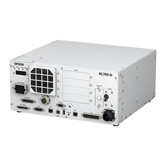
ROBOT CONTROLLER
Brand:
Epson
| Category:
Controller
| Size: 6.09 MB
Table of Contents
Table of Contents
9
Installation
17
Safety
19
Conventions
19
Installation
20
System Example
20
Unpacking
21
Transportation
21
Transportation Precautions
21
Number of People and Position to Hold, When Transporting Manipulator
21
Manipulator Installation
23
Transportation Precautions
23
Environment
23
Noise Level
24
Base Table
24
Installation Procedure
26
Control Unit Installation
31
Environment
31
Installation
32
Wall Mounting Option
34
Designing a Safe Robot System
35
Environmental Conditions
35
System Layout
35
Disabling Power to the System Using Lock out / Tag out
36
End Effector Design
36
Peripheral Equipment Design
36
Remote Control
36
Emergency Stop
37
Safeguard
38
Presence Sensing Device
40
Resetting the Safeguard
40
Robot Operation Panel
40
Connecting
41
Connection to EMERGENCY Connector
41
Power Supply
48
Connecting Manipulator and Controller
50
Saving Default Status
50
Power-ON
51
Power-ON Precautions
51
Power on Procedure
52
First Step
53
Installing EPSON RC+ 7.0 Software
53
Development PC and Controller Connection
55
About Development PC Connection USB Port
56
Precaution
56
Software Setup and Connection Check
57
Backup the Initial Condition of the Controller
58
Disconnection of Development PC and Controller
58
Moving the Robot to Initial Position
58
Writing Your First Program
63
Firmware Update
68
Updating Firmware
68
Firmware Upgrade Procedure
68
Controller Recovery
71
Firmware Initialization Procedure
72
Adding Confirmation Steps by Strengthening Security of Ethernet
74
Connection
74
Second Step
78
Connection with External Equipment
78
Remote Control
78
Ethernet
78
RS-232C (Option)
78
Analog I/O Board (Option)
78
Force Sensor I/F Board (Option)
78
Ethernet Connection of Development PC and Controller
79
Connection of Teach Pendant (Option)
79
Functions Required for Designing
81
Specifications
83
System Example
83
Standard Specifications
84
Outer Dimensions
87
Part Names and Functions
88
LED and Seven-Segment LED
91
LED and Seven-Segment LED Display
91
Particular Status Display
92
Safety Function
92
Protection Features
93
Installation
95
Unpacking
95
Environmental Requirements
95
Environment
95
Installation
96
Wall Mounting Option
99
Power Supply
100
Specifications
100
AC Power Cable
101
Cable Connection
102
Typical Cable Connection
103
Connecting Manipulator to Controller
105
Noise Countermeasures
106
Operation Mode (TEACH/AUTO/TEST)
108
Overview
108
Switch Operation Mode
109
Program Mode (AUTO)
110
What Is Program Mode (AUTO)
110
Setup from EPSON RC
110
Auto Mode (AUTO)
111
What Is Auto Mode (AUTO)
111
Setup from EPSON RC
111
Setup from Control Device
112
Development PC Connection USB Port
113
About Development PC Connection USB Port
113
Precaution
114
PC and Controller Connection Using
114
Disconnection of Development PC and Controller
115
How to Fix USB Cable
115
Memory Port
116
What Is Backup Controller Function
116
Before Using Backup Controller Function
116
Precautions
116
Adoptable USB Memory
116
Backup Controller Function
117
Backup Controller with Trigger Button
117
Load Data with EPSON RC+ 7.0
117
Transfer with E-Mail
117
Details of Data
118
LAN (Ethernet Communication) Port
119
About the LAN (Ethernet Communication) Port
119
IP Address
119
Changing Controller IP Address
120
Connection of Development PC and Controller with
121
Disconnection of Development PC and Controller
122
TP Port
123
What Is the TP Port
123
Teach Pendant Connection
124
Emergency
125
Safety Door Switch and Latch Release Switch
126
Safety Door Switch
126
Latch Release Switch
127
Checking Latch Release Switch Operation
127
Emergency Stop Switch Connection
128
Emergency Stop Switch
128
Checking Emergency Stop Switch Operation
128
Recovery from Emergency Stop
128
Pin Assignments
129
Circuit Diagrams
130
Example 1: External Emergency Stop Switch Typical Application114
130
Example 2: External Safety Relay Typical Application
131
Standard RS-232C Port
132
RS-232C Port
132
Confirmation with EPSON RC+ 7.0 (RS-232C)
132
RS-232C Software Communication Setup (RS-232C)
133
Communication Cable (RS-232C)
133
I/O Connector
134
Input Circuit
134
Typical Input Circuit Application 1
135
Typical Input Circuit Application 2
136
Output Circuit
137
Typical Output Circuit Application 1: Sink Type (NPN)
138
Typical Output Circuit Application 2: Source Type (PNP)
138
Pin Assignments
139
I/O Remote Settings
140
I/O Signal Description
141
Remote Input Signals
141
Remote Output Signals
145
Timing Specifications
148
Design Notes for Remote Input Signals
148
Timing Diagram for Operation Execution Sequence
148
Timing Diagram for Program Execution Sequence
149
Timing Diagram for Safety Door Input Sequence
150
Timing Diagram for Emergency Stop Sequence
150
R-I/O Connector
151
Input Circuit
151
Typical Input Circuit Application 1
151
Typical Input Circuit Application 2
151
Pin Assignments
152
Option Slots
153
About Option Slots
153
Expansion I/O Board
153
Board Configuration (Expansion I/O Board)
154
Confirmation with EPSON RC+ 7.0 (Expansion I/O Board)
154
Input Circuit
155
Output Circuit
157
Pin Assignments (Expansion I/O Board)
160
Fieldbus I/O Board
164
RS-232C Board
165
About the RS-232C Board
165
Board Setup (RS-232C)
165
Confirmation with EPSON RC+ (RS-232C)
166
RS-232C Software Communication Setup (RS-232C)
166
Communication Cable (RS-232C)
167
PG Board
168
Analog I/O Board
168
About Analog I/O Board
168
Board Configuration (Analog I/O Board)
169
Confirmation with EPSON RC+ (Analog I/O Board)
172
Input Circuit (Analog I/O Board)
173
Output Circuit (Analog I/O Board)
173
Pin Assignments (Analog I/O Board)
174
Force Sensor I/F Board
175
About Force Sensor I/F Board
175
Board Configuration (Force Sensor I/F Board)
175
Confirmation with EPSON RC+ (Force Sensor I/F Board)
176
EUROMAP67 Board
177
Notes on the EUROMAP67 Board
179
Board Settings (EUROMAP67 Board)
180
Installation (EUROMAP67 Board)
180
Confirming with EPSON RC+ 7.0 (EUROMAP67 Board)
181
Sample Project (EUROMAP67 Board)
181
Circuit Overview (EUROMAP67 Board)
182
Input Circuit (EUROMAP67 Board)
183
Output Circuit (EUROMAP67 Board)
183
Emergency Stop, Safeguard (EUROMAP67 Board)
184
I/O Pin Assignments (EUROMAP67 Board)
185
Emergency Stop Connecter Pin Assignments
187
(EUROMAP67 Board)
187
Regular Inspection
189
Regular Inspection for RC700-D
191
Inspections and Schedules
191
Backup and Restore
192
What Is the Backup Controller Function
192
Backup Data Types
192
Backup
193
Restore
194
Alarm
197
Maintenance
197
How to View the Maintenance Information
198
How to Edit the Maintenance Information
200
Alarm Notifying Method
201
How to Cancel the Alarm
201
Appendix
203
Appendix A: Option Parts List
205
Appendix B: Open Source Software License
206
Advertisement
Advertisement
Related Products
Epson RC700
Epson RC700-A
Epson RC700DU
Epson RC700DU-A
Epson RC620 CU
Epson RC620 DU
epson RC420
Epson RC+ 7.0
Epson RC620 Series
Epson RC520
Epson Categories
Printer
Projector
All in One Printer
Scanner
Printer Accessories
More Epson Manuals
Login
Sign In
OR
Sign in with Facebook
Sign in with Google
Upload manual
Upload from disk
Upload from URL