Mitsubishi Electric MELSECQ Series User Manual
Multichannel high-speed counter module
Hide thumbs
Also See for MELSECQ Series:
- User manual (834 pages) ,
- Reference manual (674 pages) ,
- Programming manual (624 pages)

Related Manuals for Mitsubishi Electric MELSECQ Series


Summary of Contents for Mitsubishi Electric MELSECQ Series
- Page 1 Multichannel High-Speed Counter Module User's Manual -QD63P6 -GX Configurator-CT (SW0D5C-QCTU-E) Downloaded from ManualsNet.com search engine...
- Page 2 Downloaded from ManualsNet.com search engine...
-
Page 3: Safety Precautions
SAFETY PRECAUTIONS (Read these precautions before using this product.) Before using this product, please read this manual and the relevant manuals carefully and pay full attention to safety to handle the product correctly. The precautions given in this manual are concerned with this product. For the safety precautions of the programmable controller system, please read the User's Manual for the CPU module. - Page 4 [Installation Precautions] CAUTION ● While pressing the installation lever located at the bottom of the module, fully insert the module fixing projection into the fixing hole in the base unit and press the module using the hole as a fulcrum. Incorrect module mounting may cause a malfunction, failure, or drop of the module.
- Page 5 [Wiring precautions] CAUTION ● Always ground the shielded cable on the encoder side (relay box). Failure to do may cause a malfunction. ● Correctly wire cables to the module after checking the rated voltage and terminal layout of the product. Connecting a voltage different from the rated voltage or incorrect wiring may result in a fire or failure.
-
Page 6: Conditions Of Use For The Product
CONDITIONS OF USE FOR THE PRODUCT (1) Mitsubishi programmable controller ("the PRODUCT") shall be used in conditions; i) where any problem, fault or failure occurring in the PRODUCT, if any, shall not lead to any major or serious accident; and ii) where the backup and fail-safe function are systematically or automatically provided outside of the PRODUCT for the case of any problem, fault or failure occurring in the PRODUCT. -
Page 7: Revisions
This manual confers no industrial property rights or any rights of any other kind, nor does it confer any licenses. Mitsubishi Electric Corporation cannot be held responsible for any problems involving industrial property rights which may occur as a result of using the contents noted in this manual. © 2007 MITSUBISHI ELECTRIC CORPORATION Downloaded from ManualsNet.com... -
Page 8: Table Of Contents
INTRODUCTION Thank you for purchasing the Mitsubishi programmable controller MELSEC-Q series. Before using the product, please read this manual carefully to develop full familiarity with the functions and performance of the Q series programmable controller to ensure correct use. CONTENTS SAFETY PRECAUTIONS ••••••••••••••••••••••••••••••••••••••••••••••••••••••••••••••••••••••••••••••••••••••••••••••••••••••... - Page 9 4.4.2 Example of wiring the module and an encoder•••••••••••••••••••••••••••••••••••••••••••••••••••••••••• 4 - 8 Intelligent Function Module Switch Setting •••••••••••••••••••••••••••••••••••••••••••••••••••••••••••••••••• 4 - 14 CHAPTER5 FUNCTIONS 5 - 1 to 5 - 22 Pulse Input and Count Methods ••••••••••••••••••••••••••••••••••••••••••••••••••••••••••••••••••••••••••••••••• 5 - 1 5.1.1 Types of the pulse input method •••••••••••••••••••••••••••••••••••••••••••••••••••••••••••••••••••••••••••...
- Page 10 When the QD63P6 Does Not Start Counting ••••••••••••••••••••••••••••••••••••••••••••••••••••••••••••••••••8 - 5 When the QD63P6 Does Not Normally Count ••••••••••••••••••••••••••••••••••••••••••••••••••••••••••••••••8 - 6 When the Coincidence Detection Interrupt Does Not Occur •••••••••••••••••••••••••••••••••••••••••••••••8 - 7 Error Codes List •••••••••••••••••••••••••••••••••••••••••••••••••••••••••••••••••••••••••••••••••••••••••••••••••••••8 - 8 APPENDICES APPX - 1 to APPX - 5 Appendix 1 Dedicated Instructions ••••••••••••••••••••••••••••••••••••••••••••••••••••••••••••••••••••••••••••••APPX - 1 Appendix 1.1...
-
Page 11: Compliance With Emc And Low Voltage Directives
COMPLIANCE WITH EMC AND LOW VOLTAGE DIRECTIVES (1) Method of ensuring compliance To ensure that Mitsubishi programmable controllers maintain EMC and Low Voltage Directives when incorporated into other machinery or equipment, certain measures may be necessary. Please refer to one of the following manuals. •... -
Page 12: Generic Terms And Abbreviations
GENERIC TERMS AND ABBREVIATIONS This manual describes the type QD63P6 multichannel high-speed counter module using the following generic terms and abbreviations, unless otherwise specified. Generic term and Description abbreviation QD63P6 Abbreviation for the type QD63P6 multichannel high-speed counter module Personal computer Generic term for IBM-PC/AT-compatible personal computer GX Developer Product name of the software package for the MELSEC programmable controllers. -
Page 13: Chapter1 Overview
OVERVIEW CHAPTER1 OVERVIEW This User's Manual describes the specifications, handling, and programming methods for the type QD63P6 multichannel high-speed counter module used together with the MELSEC-Q series CPU module. The QD63P6 can use the following methods in 1-phase/2-phase pulse inputs. •1 multiple of 1 phase pulse •2 multiples of 1 phase pulse •CW/CCW... -
Page 14: Features
OVERVIEW Features This section describes the features of the QD63P6. (1) Wide range of expression on counting (from -2147483648 to 2147483647) Count values can be stored in 6 channels and 32-bit signed binary. (2) Switching of the maximum counting speed Since the QD63P6 can switch between 200 k, 100 k, and 10 k, gradual rise/fall pulses can be correctly counted. -
Page 15: Chapter2 System Configuration
SYSTEM CONFIGURATION CHAPTER2 SYSTEM CONFIGURATION This chapter explains the system configuration of the QD63P6. Applicable Systems This section describes the applicable systems. (1) Applicable modules and base units, and No. of modules (a) When mounted with a CPU module The table below shows the CPU modules and base units applicable to the QD63P6 and quantities for each CPU model. - Page 16 SYSTEM CONFIGURATION Table2.1 Applicable modules, number of mountable modules, and applicable base units (Continued) Applicable CPU module Base unit No. of Extension base CPU type CPU model Main base unit modules unit Q03UDECPU Q04UDEHCPU Q06UDEHCPU Q10UDEHCPU Universal model Programmable Q13UDEHCPU Up to 64 QCPU Q20UDEHCPU...
- Page 17 SYSTEM CONFIGURATION (2) Support of the multiple CPU system The function version of the first released QD63P6 is B, and it supports multiple CPU systems. When using the QD63P6 in a multiple CPU system, refer to the following manual first. •...
-
Page 18: About Use Of The Qd63P6 With Redundant Cpu
SYSTEM CONFIGURATION About Use of the QD63P6 with Redundant CPU This section explains how to use the QD63P6 with the Redundant CPU. (1) GX Configurator-CT GX Configurator-CT cannot be used when accessing the Redundant CPU via an intelligent function module on an extension base unit from GX Developer. Connect a personal computer with a communication path indicated below Main base unit Extension base unit... -
Page 19: How To Check The Function Version/Serial No./Software Version
SYSTEM CONFIGURATION How to Check the Function Version/Serial No./Software Version Check the function version and serial No. of the QD63P6 and the GX Configurator-CT software version by the following methods. (1) Checking the rating plate on the module side The rating plate is situated on the side face of the QD63P6. Serial No. - Page 20 SYSTEM CONFIGURATION (3) Confirming the serial number on the system monitor (Product Information List) To display the screen for checking the serial number and function version, select [Diagnostics] [System monitor] and click the "Product Inf. List" button in GX Developer. Serial Function number...
- Page 21 SYSTEM CONFIGURATION (4) Checking the software version of GX Configurator-CT The software version of GX Configurator-CT can be checked in GX Developer's "Product information" screen. [Operating procedure] GX Developer [Help] [Product information] Software version (In the case of GX Developer Version 8) Figure 2.5 [Product information] screen of GX Developer Remark The version description for GX Configurator-CT has been changed as shown...
- Page 22 SYSTEM CONFIGURATION Memo 2.3 How to Check the Function Version/Serial No./Software Version Downloaded from ManualsNet.com search engine...
-
Page 23: Chapter3 Specifications
SPECIFICATIONS CHAPTER3 SPECIFICATIONS This chapter describes the performance specifications of the QD63P6, I/O signals to the programmable controller CPU, specifications of the buffer memory. For general specifications of the QD63P6, refer to the User's Manual for the CPU module. Performance Specifications The following table shows the performance specifications of the QD63P6. -
Page 24: Function List
SPECIFICATIONS Function List The following table shows the functions of the QD63P6. I/O numbers (X/Y) and buffer memory addresses in Description describe only for channel For buffer memory addresses of channel 2 or later and I/O numbers (X/Y) of channel 2 or later, refer to Section 3.4.1 and Section 3.3.1, respectively. -
Page 25: I/O Signals To The Programmable Controller Cpu
SPECIFICATIONS I/O Signals to the Programmable Controller CPU 3.3.1 I/O signal list The following table shows the I/O signals from the QD63P6 to the programmable controller CPU. Note that that I/O numbers (X/Y) and I/O addresses mentioned in this and the subsequent chapters are assumed when the QD63P6 is mounted to the null I/O slot on the main base unit. - Page 26 SPECIFICATIONS POINT The reserved devices above are for system use, not for users. If used (turning ON/OFF) by a user, the functions of the QD63P6 are not ensured. 3.3 I/O Signals to the Programmable Controller CPU 3.3.1 I/O signal list Downloaded from ManualsNet.com search engine...
-
Page 27: Functions Of I/O Signals
SPECIFICATIONS 3.3.2 Functions of I/O signals The following table shows the I/O signals of the QD63P6. I/O numbers (X/Y) and buffer memory addresses in Description describe only for channel For I/O numbers (X/Y) and buffer memory addresses from channels 2 to 6, refer to Section 3.3.1 and Section 3.4.1. - Page 28 SPECIFICATIONS Table 3.5 I/O signals (Continued) Signal name Device Description QD63P6 Programmable controller CPU •Turns ON and is the device is latched when the present value A (Un\G10 and 11)/ present value B (Un\G200 and 201) Coincidence detection point setting (Un\G6 and 7).
- Page 29 SPECIFICATIONS (2) Output signals Table 3.6 Output signals Signal name Device Operation Programmable controller Description timing QD63P6 •Turn ON to reset the counter value coincidence (X02). •Note that the ON/OFF time must be 2ms or longer. *1 Coincidence signal •Turn OFF the coincidence signal reset command (Y01) when the reset command counter value coincidence (X02) is reset.
- Page 30 SPECIFICATIONS Table 3.6 Output signals (Continued) Signal name Device Operation Programmable controller Description timing QD63P6 •Turn ON to perform count operation. •This command operates as follows when the pulse input mode is 1 multiple of 1 phase. Count enable command Count enable command (Y04) Present value A...
-
Page 31: Buffer Memory Assignment
SPECIFICATIONS Buffer Memory Assignment 3.4.1 List of buffer memory assignment The following table shows the buffer memory assignment of the QD63P6. Table 3.7 List of buffer memory assignment Address (decimal notation) Initial Setting contents Read/write Reference CH1 CH2 CH3 CH4 CH5 CH6 value*1 120 150 Ring counter lower limit value *2... - Page 32 SPECIFICATIONS POINT • Items with "*2" in Table 3.7 are stored in 32-bit signed binary to the buffer memory; therefore, make sure to read each value in units of 2 words. • Since the buffer memory contents are automatically updated by count operation, the latest count value can be read from the buffer memory.
-
Page 33: Details Of The Buffer Memory
SPECIFICATIONS 3.4.2 Details of the buffer memory This section describes details of the QD63P6 buffer memory. Each item contains the I/O numbers (X/Y) and buffer memory addresses of channel 1 only. For buffer memory addresses of channel 2 or later and I/O numbers (X/Y) of channel 2 or later, refer to Section 3.4.1 and Section 3.3.1, respectively. - Page 34 SPECIFICATIONS (3) Coincidence detection point setting (Un\G6 and 7) Coincidence detection point change request (Un\G8) • Write the coincidence detection point setting value to be compared with the present value A (Un\G10 and 11)/counter present value B (Un\G200 and 201) for counter.
- Page 35 SPECIFICATIONS (4) Period setting (Un\G9) • This area is used for writing the cycle at which the periodic pulse counter function (refer to Section 5.5) is to be performed. • Setting value when the periodic pulse counter start command (Y05) changes from OFF to ON becomes effective.
- Page 36 SPECIFICATIONS (5) Present value A (Un\G10 and 11) and present value B (Un\G200 and 201) • The present counter value is stored in this area. • Select the present value A (Un\G10 and 11) to read such as the present value and overflow detection flag (Un\G12) for each channel, and select the present value B (Un\G200 and 201) to read the present values of multiple channels at a time.
- Page 37 SPECIFICATIONS (7) Periodic counter flag (Un\G13) • Operation status of the function is stored in this area during execution of the periodic pulse counter function (refer to Section 5.5). • "0" is stored during stop of the periodic pulse counter function and "1"is stored during execution of the function in the periodic counter flag (Un\G13).
- Page 38 SPECIFICATIONS (10) Error reset command (Un\G21) • This area is used for resetting the error code stored in the error code of buffer memory (Un\G20) by "0". • Writing 1 (ON) to the error reset command (Un\G21) resets the error code. •...
-
Page 39: Interface With External Devices
SPECIFICATIONS Interface with External Devices The following table shows the list of external device interface for the QD63P6. Table 3.8 External device interface list for the QD63P6 Operating Input voltage Terminal current Internal circuit Signal name Operation (guaranteed classification number (guaranteed value) value) -
Page 40: Connectable Encoders
SPECIFICATIONS Connectable Encoders The encoders connectable to the QD63P6 are described below. • Open collector output type encoders • CMOS level voltage output type encoders (Confirm that the encoder output voltage meets the specifications for the QD63P6.) POINT The following encoder is not applicable for the QD63P6. •... -
Page 41: Chapter4 Procedures And Settings Before Operation
PROCEDURES AND SETTINGS BEFORE OPERATION CHAPTER4 PROCEDURES AND SETTINGS BEFORE OPERATION This chapter describes the operating procedures before operation, part names, settings, and wiring of the QD63P6. Handling Precautions This section describes precautions on handling the QD63P6. (1) Do not drop the module case and/or connector or apply a strong impact to it. -
Page 42: Procedures Before Operation
PROCEDURES AND SETTINGS BEFORE OPERATION Procedures before Operation The following flowchart shows the procedures for operating the QD63P6. Start Module mounting Mount the QD63P6 to the specified slot. Wiring Wire external devices to the QD63P6. Intelligent function module switch setting Set the switches with GX Developer (refer to Section 4.5). -
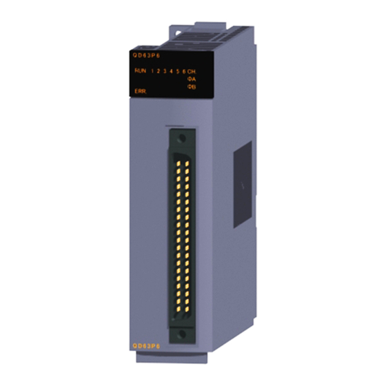
Page 43: Part Names
PROCEDURES AND SETTINGS BEFORE OPERATION Part Names The following explains the part names of the QD63P6. (Connector terminal number) (Connector terminal number) Serial number plate Figure 4.2 Appearance of the QD63P6 Table 4.2 Part names Name Description Indicates operation status of the QD63P6. ON: Normal operation OFF: Watchdog timer error Indicates error status of the QD63P6. - Page 44 PROCEDURES AND SETTINGS BEFORE OPERATION (1) Connectors for external wiring Purchase the connector for the QD63P6 separately. The following tables show the recommended connector types and crimp tool. (a) Connector types Table 4.3 Connector types Type Model Soldering type, straight out A6CON1 Crimp type, straight out A6CON2...
-
Page 45: Wiring
PROCEDURES AND SETTINGS BEFORE OPERATION Wiring This section describes wiring an encoder and controller to the QD63P6. 4.4.1 Wiring precautions One of the conditions to maximize the QD63P6 functions and make the system high- reliable, the external wiring has to be laid so that the QD63P6 becomes less subject to noise. - Page 46 PROCEDURES AND SETTINGS BEFORE OPERATION (5) The following diagram shows an example of wiring for measures against noise. Programmable controller QD63P6 Inverter Terminal Terminal Avoid using a solenoid valve and inductive load together in the same block block metallic pipe. If a sufficient distance cannot be secured with high voltage cable due to such as duct wiring, use CVVS or other shielded cable for the Install I/O wires at least high voltage cable.
- Page 47 OPERATION (7) To conform the wiring to the EMC and Low Voltage Directives, ground the shielded twisted pair cables to a control panel with the AD75CK cable clamp (manufactured by Mitsubishi Electric Corporation). In a control panel 20cm (7.87inch) 20cm (7.87inch) 20cm (7.87inch)
-
Page 48: Example Of Wiring The Module And An Encoder
PROCEDURES AND SETTINGS BEFORE OPERATION 4.4.2 Example of wiring the module and an encoder (1) Example of wiring with an encoder of open collector output type (5 VDC) QD63P6 Encoder Phase A pulse input + Phase A Shielded twisted pair cable Shield Phase A pulse input - 1/8 W... - Page 49 PROCEDURES AND SETTINGS BEFORE OPERATION POINT When wiring the QD63P6 and an encoder, separate the power supply cable and signal line. The following diagram shows an example of wiring with Phase A. (Wire Phase B as well). [Wiring example] Shielded twisted pair cable QD63P6 Pulse input -...
- Page 50 PROCEDURES AND SETTINGS BEFORE OPERATION (2) Example of wiring with an encoder of open collector output type (12/24 VDC) Load resistance 12 V 820 1/4 W QD63P6 Encoder 24 V 2200 1/2W Phase A pulse input + Phase A Shielded 12/24 V twisted pair cable Shield...
- Page 51 PROCEDURES AND SETTINGS BEFORE OPERATION POINT When wiring the QD63P6 and an encoder, separate the power supply cable and signal line. The following diagram shows an example of wiring with Phase A. (Wire Phase B as well). [Wiring example] Shielded twisted pair cable QD63P6 Pulse input -...
- Page 52 PROCEDURES AND SETTINGS BEFORE OPERATION (3) Example of wiring with an encoder of voltage output type (5 VDC) QD63P6 Encoder Phase A pulse input + Phase A Shielded twisted pair cable Shield Phase A pulse input - 1/8 W Phase B pulse input + Phase B Shielded twisted pair cable...
- Page 53 PROCEDURES AND SETTINGS BEFORE OPERATION (4) Example of wiring with an encoder of voltage output type (12/24 VDC) Load resistance 12 V 820 1/4 W QD63P6 Encoder 24 V 2200 1/2W Phase A pulse input + Phase A Shielded twisted pair cable Shield Phase A pulse input - 1/8 W...
-
Page 54: Intelligent Function Module Switch Setting
PROCEDURES AND SETTINGS BEFORE OPERATION Intelligent Function Module Switch Setting This section describes the intelligent function module switch setting. The switch setting is made on the [I/O assignment] screen of GX Developer. (1) Intelligent function module switch setting The switch has five switches and is set at 16-bit data. When the switch setting is not made, the default values of the switches from 1 to 5 are Table 4.7 Intelligent function module switches Setting item... - Page 55 PROCEDURES AND SETTINGS BEFORE OPERATION (Example) Target channel: channel 1, pulse input mode setting: 1 multiple of 2 phases, counting speed setting: 200 kPPS, counter format: ring counter, and present value selection setting: setting value B Set the switch 1 0003 Set the switch 3 0002...
- Page 56 PROCEDURES AND SETTINGS BEFORE OPERATION (3) Operating procedure Set the switches on the [I/O assignment] screen of GX Developer. (a) [I/O assignment] screen Make the following settings to the slot to which the QD63P6 is mounted. [Type]: Select [Intelli]. [Model name]: Input the model of the module. [Points]: Select [32points].
-
Page 57: Chapter5 Functions
FUNCTIONS CHAPTER5 FUNCTIONS This chapter describes functions of the QD63P6. Pulse Input and Count Methods 5.1.1 Types of the pulse input method There are six kinds of the pulse input methods: 1 phase pulse input (1 or 2 multiples), CW/ CCW pulse input, and 2 phases pulse input (1, 2 or 4 multiples). - Page 58 FUNCTIONS Table 5.1 Types of the pulse input method (Continued) Pulse input Count timing method When B is OFF, counts on the rising edge ( ) of For addition count When B is ON, counts on the falling edge ( ) of 2 multiples of 2 phases...
-
Page 59: Selecting Counter Format
FUNCTIONS Selecting Counter Format By selecting a counter format, the following counter operations are available. (1) Linear counter The linear counter generates an overflow error when the count value exceeds the count range of the QD63P6. (2) Ring counter (a) Counting is repeated within the range between the arbitrarily-set ring counter upper limit value (Un\G2 and 3) and ring counter lower limit value (Un\G0 and 1). -
Page 60: Selecting The Linear Counter
FUNCTIONS 5.2.1 Selecting the linear counter (1) Linear counter operation When the linear counter is selected, counting is operated in a range between - 2147483648 (lower limit value) and 2147483647 (upper limit value). This can be used in combination with the preset function and the coincidence detection function. -
Page 61: Selecting The Ring Counter
FUNCTIONS 5.2.2 Selecting the ring counter (1) Ring counter operation When the ring counter is selected, counting is repeated within the range between the ring counter lower limit value (Un\G0 and 1) and ring counter upper limit value (Un\G2 and 3), which are arbitrarily set in the buffer memory. No overflow error will occur when the ring counter is selected. - Page 62 FUNCTIONS (a) When using within the specified range 1) Normally the following range is applied. " Ring counter lower limit Present value A/ Ring counter upper limit " value present value B value Un\G0 and 1 Un\G10 and 11 Un\G2 and 3 Un\G200 and 201 a) General operation Present counter value...
- Page 63 FUNCTIONS d) Setting example When the count is enabled with a ring counter lower limit value Un\G0 and of 0, ring counter upper limit value Un\G2 and 3 of 2000, and present value A Un\G10 and 11 /present value B Un\G200 and 201 of 500 Present counter value...
- Page 64 FUNCTIONS 2) When the following range is applied, the operation is as shown in Figure 5.5. "Present value A/present value B Ring counter lower limit value" (Un\G10 and 11)/ (Un\G0 and 1) (Un\G200 and 201) "Ring counter upper limit value Present value A/present value B"...
- Page 65 FUNCTIONS c) Count operation • Addition count Even if the present value A Un\G10 and 11 /present value B Un\G200 and 201 reaches the ring counter lower limit value Un\G0 and 1 , the ring counter lower limit value Un\G0 and 1 is held as it is.
- Page 66 FUNCTIONS (b) When using in the entire range a) General operation By setting the same value in the ring counter upper limit value (Un\G2 and 3) and ring counter lower limit value (Un\G0 and 1), the count operation is repeated in the entire range of the QD63P6 (from -2147483648 (lower limit value) to 2147483647 (upper limit value)).
- Page 67 FUNCTIONS POINT (1) When changing the ring counter upper/lower limit value, perform the following: • Turn OFF the count enable command (Y04) for 2ms or longer. • Change the setting of the ring counter upper limit value (Un\G2 and 3) and/or ring counter lower limit value (Un\G0 and 1).
-
Page 68: Using The Coincidence Detection Function
FUNCTIONS Using the Coincidence Detection Function When using the coincidence detection function, set any count value in advance. Then, the QD63P6 compares the value with the present A (Un\G10 and 11)/present value B (Un\G200 and 201) of the counter, and outputs the counter value coincidence (X02) when they match. - Page 69 FUNCTIONS Table 5.2 Details of the coincidence detection operation example Description Coincidence detection is started by the following steps using the value set in the coincidence detection point setting (Un\G6 and 7). (1) Write a coincidence detection value (100) into the coincidence detection point setting (Un\G6 and 7).
- Page 70 FUNCTIONS (2) Coincidence detection interrupt function The coincidence detection interrupt function allows making an interrupt request to a programmable controller CPU at the time of coincidence detection to start the interrupt program. (Depending on the programmable controller CPU used, the coincidence detection interrupt function cannot be used.
- Page 71 FUNCTIONS 3) Intelli. module side [Start I/O No.] Set the start I/O number of the QD63P6. Setting range: 0000 to 0FE0 ( 4) Intelli. module side [Start SI No.] Set the start interrupt factor (SI) No. of the QD63P6. Setting range: 0 to 5 The following shows a setting example where SI 0 to 5 of the QD63P6 in the slot of start I/O No.20 are assigned to interrupt pointers I50 to I55.
- Page 72 FUNCTIONS POINT • A coincidence detection interrupt occurs when the counter value coincidence (X02) rises (from OFF to ON). This means that, if the coincidence signal is reset and unless the counter value coincidence (X02) is turned OFF, the next interrupt request will not be issued. •...
-
Page 73: Using The Preset Function
FUNCTIONS Using the Preset Function The preset function is used to replace the counter's present value A (Un\G10 and 11)/ present value B (Un\G200 and 201) with any given value (preset value), from which the pulse counting can be started. (1) Preset function operation The preset function is activated by turning ON the preset command (Y02) on the sequence program. -
Page 74: Using The Periodic Pulse Counter Function
FUNCTIONS Using the Periodic Pulse Counter Function This function allows the present value A (Un\G10 and 11)/present value B (Un\G200 and 201) and the previous value to be stored in the present periodic pulse count value (Un\G16 and 17) and previous periodic pulse count value (Un\G14 and 15) respectively at intervals of the preset period time (Un\G9), while the periodic pulse counter start command (Y05) is ON. - Page 75 FUNCTIONS Count enable command (Y04) Present value A (Un\G10 and 11) Periodic pulse counter start command (Y05) (Period setting) (Un\G9) Present periodic pulse count value (Un\G16 and 17) Previous periodic pulse count value (Un\G14 and 15) Judgment value for updated periodic pulse count value (Un\G18 and 19) Periodic counter flag...
- Page 76 FUNCTIONS Table 5.5 Details of the periodic pulse counter function operation example Description The counter's present value A (Un\G10 and 11)/present value B (Un\G200 and 201), "0" is stored in the present periodic pulse count value (Un\G16 and 17). The counter's present value A (Un\G10 and 11)/present value B (Un\G200 and 201), "200"...
- Page 77 FUNCTIONS POINT When reading a periodic pulse count value with the sequence program, use either of the following methods. (1) Read a data block of six words from the previous periodic pulse count value (Un\G14 and 15) using the DFRO instruction, and check that the previous periodic pulse count value (Un\G14 and 15) is equal to the judgment value for updated periodic pulse count value (Un\G18 and 19).
-
Page 78: Response Delay Time
FUNCTIONS Response Delay Time This section described the response delay time of I/O signals and buffer memory. Maximum delay time [ms] = [Time of (1)] + [Maximum time of (2)] = Scan time of a sequence program + 2 [ms] (1) Scan time of a sequence program The CPU module processes I/O signals by refreshing them all at once before the operation start of a sequence program. -
Page 79: Chapter6 Utility Package (Gx Configurator-Ct)
UTILITY PACKAGE (GX Configurator-CT) CHAPTER6 UTILITY PACKAGE (GX Configurator-CT) Utility Package Functions Table 6.1 shows the functions of the utility package. Table 6.1 Utility package (GX Configurator-CT) functions list Function Description Reference (1) Make the initial settings for each channel to operate the QD63P6. Set the values of the items where initial settings are required. -
Page 80: Installing And Uninstalling The Utility Package
UTILITY PACKAGE (GX Configurator-CT) Installing and Uninstalling the Utility Package For how to install or uninstall the utility package, refer to "Method of installing the MELSOFT Series" included in the utility package. 6.2.1 Handling precautions The following explains the precautions on using the utility package. (1) For safety Since the utility is add-in software for GX Developer, read "Safety Precautions"... - Page 81 UTILITY PACKAGE (GX Configurator-CT) Table 6.2 Maximum number of settable parameters using GX Configurator When intelligent function modules Maximum number of parameter settings Initial setting Auto refresh setting are installed to: Q00J/Q00/Q01CPU Q02/Q02H/Q06H/Q12H/Q25HCPU Q02PH/Q06PH/Q12PH/Q25PHCPU Q12PRH/Q25PRHCPU Q00UJ/Q00U/Q01UCPU Q02UCPU 2048 1024 Q03UD/Q04UDH/Q06UDH/Q10UDH/ Q13UDH/Q20UDH/Q26UDH/ Q03UDE/Q04UDEH/Q06UDEH/ 4096...
-
Page 82: Operating Environment
UTILITY PACKAGE (GX Configurator-CT) 6.2.2 Operating environment This section explains the operating environment of the personal computer that runs GX Configurator-CT. Table 6.4 Operating environment of the personal computer Item Description Installation (Add-in) target Add-in to GX Developer Version 4 (English version) or later. Computer A personal computer with the operating systems below. - Page 83 UTILITY PACKAGE (GX Configurator-CT) Table 6.5 Operating system and performance required for personal computer Performance required for personal computer Operating system Memory ® ® 32 MB or more Windows Pentium 133 MHz or more ® ® 32 MB or more Windows Pentium 133 MHz or more...
-
Page 84: Utility Package Operation
UTILITY PACKAGE (GX Configurator-CT) Utility Package Operation 6.3.1 Common utility package operations (1) Control keys Table 6.6 shows the special keys that can be used in operations of the utility package and their applications. Table 6.6 Control keys Application Cancels the current entry in a cell. Closes the window. - Page 85 UTILITY PACKAGE (GX Configurator-CT) (b) Steps 1) to 3) shown in Figure 6.3 are performed as follows: 1) From GX Developer, select: [Project] [Open project]/[Save]/[Save as] 2) On the intelligent function module selection screen of the utility, select: [Intelligent function module parameter] [Open parameters]/[Save parameters] 3) From GX Developer, select:...
-
Page 86: Operation Overview
UTILITY PACKAGE (GX Configurator-CT) 6.3.2 Operation overview GX Developer screen [Tools] - [Intelligent function utility] - [Start] Screen for selecting a target intelligent function module Refer to Section 6.3.3. Enter "Start I/O No.", and select "Module type" and "Module model name". Initial setting Auto refresh Auto refresh setting screen... - Page 87 UTILITY PACKAGE (GX Configurator-CT) [Online] - [Monitor/Test] Selecting monitor/test module screen Select a module to Monitor/Test be monitored/tested. Monitor/Test screen Refer to Section 6.6. Figure 6.4 General operation (Continued) 6.3 Utility Package Operation 6.3.2 Operation overview Downloaded from ManualsNet.com search engine...
-
Page 88: Starting The Intelligent Function Module Utility
UTILITY PACKAGE (GX Configurator-CT) 6.3.3 Starting the Intelligent function module utility [Operating procedure] Intelligent function module utility is started from GX Developer. [Tools] [Intelligent function utility] [Start] [Setting screen] Figure 6.5 [Intelligent function module utility] screen [Explanation of items] (1) Activation of other screens Following screens can be displayed from the intelligent function module utility screen. - Page 89 UTILITY PACKAGE (GX Configurator-CT) (2) Command buttons Deletes the initial setting and auto refresh setting of the selected module. Closes this screen. 6.3 Utility Package Operation - 11 6.3.3 Starting the Intelligent function module utility Downloaded from ManualsNet.com search engine...
- Page 90 UTILITY PACKAGE (GX Configurator-CT) (3) Menu bar (a) File menu Intelligent function module parameters of the project opened by GX Developer are handled. [Open parameters] : Reads a parameter file. [Close parameters] : Closes the parameter file. If any data are modified, a dialog asking for file saving will appear.
-
Page 91: Initial Setting
UTILITY PACKAGE (GX Configurator-CT) Initial Setting [Purpose] Make the initial settings for each channel to operate the QD63P6. The following setting items are available for parameters of [Initial setting]. • Preset value setting • Ring counter lower limit value • Coincidence detection point change request •... - Page 92 UTILITY PACKAGE (GX Configurator-CT) [Explanation of items] (1) Command buttons Creates a file containing the screen data in text file format. Saves the set data and ends the operation. Cancels the setting and ends the operation. POINT Initial settings are stored to the intelligent function module parameters. The initial settings become effective after writing them to the CPU module and executing (1) or (2).
-
Page 93: Auto Refresh
UTILITY PACKAGE (GX Configurator-CT) Auto Refresh [Purpose] Set the buffer memory of the QD63P6 to which auto refresh is to be performed for each channel. The following setting items are available for parameters of [Auto refresh setting]. • Present value A •... - Page 94 UTILITY PACKAGE (GX Configurator-CT) [Explanation of items] (1) Items Module side Buffer size : Displays the buffer memory size of the setting item. Module side Transfer word : Displays the number of words to be transferred. count Transfer direction : " " indicates that data are written from the programmable controller CPU to the buffer memory.
-
Page 95: Monitoring/Test
UTILITY PACKAGE (GX Configurator-CT) Monitoring/Test 6.6.1 Monitoring/Test [Purpose] Start buffer memory monitoring/testing and I/O signal monitoring/testing from this screen. [Operating procedure] "Select monitor/test module" screen "Start I/O No.*" "Module type" "Module model name" Enter the start I/O No. in hexadecimal. The screen can also be started from System monitor of GX Developer Version 6 or later. - Page 96 UTILITY PACKAGE (GX Configurator-CT) [Setting screen] Selecting these buttons displays the following screens. X/Y Monitor/Test Preset function Figure 6.8 [Monitor/Test] screen 6.6 Monitoring/Test - 18 6.6.1 Monitoring/Test Downloaded from ManualsNet.com search engine...
- Page 97 UTILITY PACKAGE (GX Configurator-CT) Ring counter function Coincidence detection Periodic pulse counter function function Figure 6.8 [Monitor/Test] screen (Continued) 6.6 Monitoring/Test - 19 6.6.1 Monitoring/Test Downloaded from ManualsNet.com search engine...
- Page 98 UTILITY PACKAGE (GX Configurator-CT) [Explanation of items] (1) Items Setting item : Displays I/O signals and buffer memory names. Current value : Monitors the I/O signal states and present buffer memory values. Setting value : Enter or select values to be written into the buffer memory for test operation.
-
Page 99: Chapter7 Programming
PROGRAMMING CHAPTER7 PROGRAMMING This chapter describes programs using channel 1 of QD63P6, whose system configuration example shown below, in the following two cases: • GX Configurator-CT is used • GX Configurator-CT is not used When applying any of the program examples introduced in this chapter to the actual system, verify the applicability and confirm that no problem occurs in the system control. - Page 100 PROGRAMMING Table 7.3 Auto refresh setting Item Setting value CH1 Present value A CH1 Overflow detection flag CH1 Previous periodic pulse count value D114 CH1 Present periodic pulse count value D116 CH1 Judgment value for updated periodic pulse D118 count value CH1 Error code D120 * 1 Set this only when using the linear counter function.
-
Page 101: Program Example When Gx Configurator-Ct Is Used
PROGRAMMING Program Example when GX Configurator-CT is Used 7.1.1 GX Configurator-CT operation (1) Initial setting (refer to Section 6.4.) Figure 7.2 shows settings have to be made. Figure 7.2 [Initial setting] screen Table 7.5 Items on the [Initial setting] screen Setting item Description Setting... - Page 102 PROGRAMMING (2) Auto refresh setting (refer to Section 6.5.) Set the values on the screen as shown in Figure 7.3. (Channel 1 is used.) Figure 7.3 [Auto refresh setting] screen Table 7.6 Items on the [Auto refresh setting] screen Setting item Description Setting CH1 Present value A...
-
Page 103: Program Example
PROGRAMMING 7.1.2 Program example <Initial setting> Set only when the counter value coincidence (X02) Module Initial READY Count setting Coincidence is turned OFF at enable completed signal reset initial setting. command signal command Initial setting completed signal <Count operation start> Module Count READY... - Page 104 PROGRAMMING <Overflow detection processing> Set only when the Module Overflow Overflow linear counter READY status occurrence function is used. storage confirmation LED signal <Error reset processing> Error Error code Error code Error code occurrence storage Error occurrence confirmation LED signal Error reset Error CH1 Error...
-
Page 105: Program Example When Gx Configurator-Ct Is Not Used
PROGRAMMING Program Example when GX Configurator-CT is not Used 7.2.1 Program example when dedicated instructions are used <Initial setting> Module CH1 Count Initial setting CH1 Preset READY enable completed value setting command signal Coincidence detection point setting Coincidence detection point change request CH1 Ring counter... - Page 106 PROGRAMMING <Present value storage> Module Present value Present READY read signal Present value value A storage <Processing at count coincidence> Module Coincidence READY Counter Coincidence confirmation value signal reset LED signal coincidence command Coincidence Counter LED clear Coincidence value signal signal reset coincidence command...
- Page 107 PROGRAMMING <Error reset processing> Error CH1 Error Error code occurrence code Error code Error code Error code storage Error occurrence confirmation LED signal Error reset Error CH1 Error command occurrence reset confirmation command LED signal 7.2 Program Example when GX Configurator-CT is not Used 7.2.1 Program example when dedicated instructions are used Downloaded from ManualsNet.com...
-
Page 108: Program Example When Dedicated Instructions Are Not Used
PROGRAMMING 7.2.2 Program example when dedicated instructions are not used <Initial setting> Module CH1 Count Initial setting CH1 Preset READY enable completed value setting command signal Coincidence detection point setting Coincidence detection point change request CH1 Ring counter lower limit Set only when the value ring counter... - Page 109 PROGRAMMING <Present value storage> Module Present value Present READY read signal Present value value A storage <Processing at count coincidence> Module Coincidence READY Counter Coincidence confirmation value signal reset LED signal coincidence command Coincidence Counter LED clear Coincidence value signal signal reset coincidence command...
- Page 110 PROGRAMMING <Error reset processing> Error CH1 Error Error code occurrence code Error code Error code Error code storage Error occurrence confirmation LED signal Error reset Error CH1 Error command occurrence reset confirmation command LED signal 7.2 Program Example when GX Configurator-CT is not Used - 12 7.2.2 Program example when dedicated instructions are not used Downloaded from...
-
Page 111: Program Example When The Coincidence Detection Interrupt Function Is Used
PROGRAMMING Program Example when the Coincidence Detection Interrupt Function is Used This section describes a program example to start an interrupt program upon detecting coincidence of coincidence detection point of channel 1. (1) System configuration QD63P6 (X/Y0 to X/Y1F) Figure 7.4 System configuration when the coincidence detection interrupt function is used (2) Program conditions (a) Interrupt pointer setting Set the values at [PLC parameter] - [PLC system] - [Intelligent function module... - Page 112 PROGRAMMING (3) Program example An interrupt must be enabled using the IMASK instruction before using an interrupt pointer. <Enabling interrupt of I50> QD63P6 program <Interrupt program> Interrupt program POINT • When the above described program is executed, only I50 interrupt program is execution-enabled and other interrupt programs are execution-disabled.
-
Page 113: Chapter8 Troubleshooting
TROUBLESHOOTING CHAPTER8 TROUBLESHOOTING This chapter describes the description of errors regarding the QD63P6 and troubleshooting for it. Error Processing and Recovery Methods 8.1.1 Checking error description using System Monitor of GX Developer Error codes can be checked by selecting [Module's Detailed Information...] on the [System Monitor] screen of GX Developer. - Page 114 TROUBLESHOOTING (3) Checking Module's Detailed Information Check the status of LEDs and intelligent function module switch setting, and module information in [H/W status] on the [Module's Detailed Information] screen which can be displayed from [System Monitor] of GX Developer Version 7.17T or later. [Setting procedure] Select [Diagnostics] [System monitor...]...
- Page 115 TROUBLESHOOTING The LED display changes according to the operation status of the QD63P6 as follows. Table 8.3 LED display Display contents Display point Operation status Action If the RUN LED does not turn ON after •RUN LED is OFF. Hardware fault the programmable controller is powered ON, the module is a failure.
-
Page 116: When The Run Led Turns Off
TROUBLESHOOTING 8.1.2 When the RUN LED turns OFF Table 8.4 When the RUN LED turns OFF Check item Action Reference Check if the service voltage of the power supply Is power supplied? module is within the rated range. Calculate the consumption current of the modules Is the capacity of the power supply module mounted to the base unit such as CPU module, I/O sufficient? -
Page 117: When The Qd63P6 Does Not Start Counting
TROUBLESHOOTING When the QD63P6 Does Not Start Counting Table 8.6 When the QD63P6 does not start counting Check item Action Reference If the LED on the programmable controller CPU Doesn't the programmable controller CPU indicates an error, correct the error with reference indicate an error? to troubleshooting in the programmable controller CPU's manual for normal operation. -
Page 118: When The Qd63P6 Does Not Normally Count
TROUBLESHOOTING When the QD63P6 Does Not Normally Count Table 8.7 When the QD63P6 does not normally count Check item Action Reference Check the pulse waveform with synchronoscope. When the input pulse does Does the input pulse waveform meet the performance not meet the performance specifications, Section 3.1 specifications? -
Page 119: When The Coincidence Detection Interrupt Does Not Occur
TROUBLESHOOTING When the Coincidence Detection Interrupt Does Not Occur Table 8.8 When the coincidence detection interrupt does not occur Check item Action Reference Change the CPU module to the one which Does the CPU module support the coincidence supports the intelligent function module event Section 2.1 (1) detection interrupt function? interrupt. -
Page 120: Error Codes List
TROUBLESHOOTING Error Codes List This section describes the descriptions and corrective actions for the errors detected by the QD63P6. Table 8.9 Error codes list Error Operation at error Error name Description Action Reference code Error channel Other channels (Normal) The present value A (Un\G10 and 11)/present value B The linear (Un\G200 and 201) exceeds the... - Page 121 TROUBLESHOOTING POINT (1) When another error occurs during error occurrence, take the following action. • When an error code from 100 to 600 occurs, the latest error code is ignored and the error code stored before the latest error code is held. •...
-
Page 122: Appendices
APPENDICES APPENDICES Appendix 1 Dedicated Instructions Appendix 1.1 Dedicated instructions list The following table shows the dedicated instructions supported by the QD63P6. Table APPX.1 Dedicated instructions supported by the QD63P6 Dedicated Function Description Reference instruction G(P).PPCVRD1 Reads the periodic pulse count value of CH1. G(P).PPCVRD2 Reads the periodic pulse count value of CH2. -
Page 123: Appendix 1.2 G(P). Ppcvrd
APPENDICES Appendix 1.2 G(P). PPCVRD Table APPX.2 Available devices Available device Link direct device Intelligent Internal device Setting Constant Other function Index (system, user) data File register module register Z Word Word K, H U \G [Instruction symbol] [Executing condition] Command G.PPCVRD G.PPCVRD... - Page 124 APPENDICES (1) Function (a) Reads the periodic pulse count value. (b) When reading the periodic pulse count value with the G(P).PPCVRD instruction, consistency between the previous periodic pulse count value and the present periodic pulse count value is retained. (Refer to Section 5.5.) (c) Completion device (D) and completion status indication device (D) +1 are available for the interlock signal of the G(P).PPCVRD instruction.
- Page 125 APPENDICES (3) Program example The following example shows the program which reads the periodic pulse count value of CH 1 for the QD63P6 mounted to to the slot where I/O number X/Y00 to X/Y1F are assigned when the read command M0 is turned ON. PPCVRD1 PPCVRD1 PPCVRD1...
-
Page 126: Appendix 2 External Dimensions
APPENDICES Appendix 2 External Dimensions 23 (0.91) 90 (3.54) 46 (1.81) 27.4 (1.08) 136 (5.35) Unit: mm (inch) APPX Appendix 2 External Dimensions Downloaded from ManualsNet.com search engine... - Page 127 INDEX Applicable System••••••••••••••••••••••••••••••••••••••• 2-1 Features ••••••••••••••••••••••••••••••••••••••••••••••••••• 1-2 Auto refresh•••••••••••••••••••••••••••••••••••••••••••••• 6-15 Function List •••••••••••••••••••••••••••••••••••••••••••••• 3-2 A6CON1••••••••••••••••••••••••••••••••••••••••••••••••••• 4-4 Function version •••••••••••••••••••••••••••••••••••• 2-3,2-5 A6CON2••••••••••••••••••••••••••••••••••••••••••••••••••• 4-4 Functions of I/O signals •••••••••••••••••••••••••••••••• 3-5 A6CON3••••••••••••••••••••••••••••••••••••••••••••••••••• 4-4 Functions of the utility package ••••••••••••••••••••••• 6-1 A6CON4••••••••••••••••••••••••••••••••••••••••••••••••••• 4-4 G(P). PPCVRD••••••••••••••••••••••••••••••••••••• APPX-2 Buffer Memory Assignment••••••••••••••••••••••••••••...
- Page 128 Periodic pulse counter start command •••••••••••••• 3-8 When the RUN LED turns OFF ••••••••••••••••••••••• 8-4 Present periodic pulse count value (Un\G16 and 17) Wiring •••••••••••••••••••••••••••••••••••••••••••••••••••••• 4-5 ••••••••••••••••••••••••••••••••••••••••••••••••••••••••••••• 3-15 Wiring precautions••••••••••••••••••••••••••••••••••••••• 4-5 Present value A (Un\G10 and 11) ••••••••••••••••••• 3-14 Present value B (Un\G200 and 201)•••••••••••••••• 3-14 Numerics Present value selection setting •••••••••••••••...
- Page 129 WARRANTY Please confirm the following product warranty details before using this product. 1. Gratis Warranty Term and Gratis Warranty Range If any faults or defects (hereinafter "Failure") found to be the responsibility of Mitsubishi occurs during use of the product within the gratis warranty term, the product shall be repaired at no cost via the sales representative or Mitsubishi Service Company.
- Page 130 Microsoft, Windows, Windows NT, and Windows Vista are registered trademarks of Microsoft Corporation in the United States and other countries. Pentium is a trademark of Intel Corporation in the United States and other countries. Ethernet is a trademark of Xerox Corporation. All other company names and product names used in this manual are trademarks or registered trademarks of their respective companies.
- Page 131 Downloaded from ManualsNet.com search engine...
- Page 132 SH(NA)-080692ENG-E(1202)MEE MODEL: QD63P6-U-SY-E MODEL CODE: 13JZ03 HEAD OFFICE : TOKYO BUILDING, 2-7-3 MARUNOUCHI, CHIYODA-KU, TOKYO 100-8310, JAPAN NAGOYA WORKS : 1-14 , YADA-MINAMI 5-CHOME , HIGASHI-KU, NAGOYA , JAPAN When exported from Japan, this manual does not require application to the Ministry of Economy, Trade and Industry for service transaction permission.