Mitsubishi Electric CITY MULTI PEFY-P06NMAU-E4 Technical & Service Manual
Hide thumbs
Also See for CITY MULTI PEFY-P06NMAU-E4:
- Installation manual (40 pages) ,
- Operation manual (32 pages) ,
- Data book (32 pages)
Table of Contents
Advertisement
Quick Links
Advertisement
Table of Contents

Related Manuals for Mitsubishi Electric CITY MULTI PEFY-P06NMAU-E4


Summary of Contents for Mitsubishi Electric CITY MULTI PEFY-P06NMAU-E4
- Page 2 It may also be in violation of applicable laws. Only use accessories (i.e., air cleaners, humidifiers, electric MITSUBISHI ELECTRIC CORPORATION cannot be held heaters) recommended by MITSUBISHI ELECTRIC COR- responsible for malfunctions or accidents resulting from the PORATION.
- Page 3 MITSUBISHI ELECTRIC CORPORATION may Only use the type of refrigerant that is indicated on the unit result in smoke, fire, or explosion.
- Page 4 Precautions for handling units for use with R410A CAUTION Do not use the existing refrigerant piping. Only use R410A. A large amount of chlorine that may be contained in the re- The use of other types of refrigerant that contain chloride sidual refrigerant and refrigerator oil in the existing piping may cause the refrigerator oil to deteriorate.
- Page 5 HWE20150...
-
Page 6: Table Of Contents
CONTENTS I Features [1] Features............................ 1 II Components and Functions [1] Components and Functions...................... 2 III Specifications [1] Specifications..........................5 1.Specifications.......................... 5 2.Electrical component specifications..................8 IV Outlines and Dimensions [1] Outlines and Dimensions......................9 V Wiring Diagram [1] Wiring Diagram ........................11 VI Refrigerant System Diagram [1] Refrigerant system diagram.................... - Page 7 HWE20150...
-
Page 8: Features
[ I Features ] I Features [1] Features Model Cooling capacity/Heating capacity BTU/h PEFY-P06NMAU-E4 6000/6700 1.8/2.0 PEFY-P08NMAU-E4 8000/9000 2.3/2.6 PEFY-P12NMAU-E4 12000/13500 3.5/4.0 PEFY-P15NMAU-E4 15000/17000 4.4/5.0 PEFY-P18NMAU-E4 18000/20000 5.3/5.9 PEFY-P24NMAU-E4 24000/27000 7.0/7.9 PEFY-P27NMAU-E4 27000/30000 7.9/8.8 PEFY-P30NMAU-E4 30000/34000 8.8/10.0 PEFY-P36NMAU-E4 36000/40000 10.6/11.7 PEFY-P48NMAU-E4 48000/54000 14.1/15.8... -
Page 9: Components And Functions
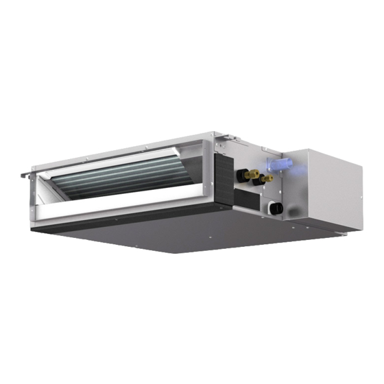
[ II Components and Functions ] II Components and Functions [1] Components and Functions 1. Indoor (Main) Unit (1) In case of rear inlet (2) In case of bottom inlet Air inlet Air inlet Air outlet Air outlet - 2 - HWE20150... - Page 10 [ II Components and Functions ] 2. Remote Controller [PAR-40MAAU] Once the operation mode is selected, the unit will remain in the selected mode until changed. (1) Remote Controller Interface ⑤ ⑥ ④ ③ ② ① Function buttons ⑦ ⑧ ⑨...
- Page 11 [ II Components and Functions ] (2) Remote Controller Display The main display can be displayed in two different modes: “Full” and “Basic.” The factory setting is “Full.” To switch to the “Basic” mode, change the setting on the Main display setting. ▌...
-
Page 12: Specifications
[ III Specifications ] III Specifications [1] Specifications 1. Specifications Model PEFY-P06NMAU-E4 PEFY-P08NMAU-E4 PEFY-P12NMAU-E4 PEFY-P15NMAU-E4 Power source 1-phase 208/230V 60Hz Cooling capacity BTU / h 6,000 8,000 12,000 15,000 (Nominal) Power input 0.042 0.042 0.052 0.062 Current input 0.42/0.38 0.42/0.38 0.56/0.51 0.64/0.58 Heating capacity... - Page 13 [ III Specifications ] Model PEFY-P18NMAU-E4 PEFY-P24NMAU-E4 PEFY-P27NMAU-E4 PEFY-P30NMAU-E4 Power source 1-phase 208/230V 60Hz Cooling capacity BTU / h 18,000 24,000 27,000 30,000 (Nominal) Power input 0.082 0.142 0.142 0.142 Current input 0.82/0.74 1.24/1.12 1.24/1.12 1.24/1.12 Heating capacity BTU / h 20,000 27,000 30,000...
- Page 14 [ III Specifications ] Model PEFY-P36NMAU-E4 PEFY-P48NMAU-E4 PEFY-P54NMAU-E4 Power source 1-phase 208/230V 60Hz Cooling capacity BTU / h 36,000 48,000 54,000 (Nominal) 10.6 14.1 15.8 Power input 0.222 0.242 0.252 Current input 2.01/1.82 2.06/1.87 2.29/2.07 Heating capacity BTU / h 40,000 54,000 60,000...
-
Page 15: Electrical Component Specifications
[ III Specifications ] 2. Electrical component specifications Sym- Component PEFY-P06NMAU-E4 PEFY-P08NMAU-E4 PEFY-P12NMAU-E4 Room temperature TH21 Resistance 0°C/15kΩ, 10°C/9.6kΩ, 20°C/6.3kΩ, 25°C/5.4kΩ, 30°C/4.3kΩ, 40°C/3.0kΩ thermistor Liquid pipe thermistor TH22 Resistance 0°C/15kΩ, 10°C/9.6kΩ, 20°C/6.3kΩ, 25°C/5.4kΩ, 30°C/4.3kΩ, 40°C/3.0kΩ Gas pipe thermistor TH23 Resistance 0°C/15kΩ, 10°C/9.6kΩ, 20°C/6.3kΩ, 25°C/5.4kΩ, 30°C/4.3kΩ, 40°C/3.0kΩ 250 VAC 6.3A Fuse 400 VDC 3A... -
Page 16: Outlines And Dimensions
[ IV Outlines and Dimensions ] IV Outlines and Dimensions [1] Outlines and Dimensions 1. PEFY-P06, 08, 12, 15, 18, 24, 27, 30, 36, 48, 54NMAU-E4 Unit : mm(in.) - 9 - HWE20150... - Page 17 [ IV Outlines and Dimensions ] Unit : mm(in.) - 10 - HWE20150...
-
Page 18: Wiring Diagram
[ V Wiring Diagram ] V Wiring Diagram [1] Wiring Diagram 1. PEFY-P06, 08, 12, 15, 18, 24, 27, 30, 36, 48, 54NMAU-E4 5 5 8 - 11 - HWE20150... -
Page 19: Refrigerant System Diagram
[ VI Refrigerant System Diagram ] VI Refrigerant System Diagram [1] Refrigerant system diagram Gas pipe thermistor TH23 Gas pipe Liquid pipe Brazed connections Strainer (#100 mesh) Linear expansion valve Liquid pipe thermistor TH22 Heat exchanger Room temperature thermistor TH21 Capacity PEFY-P06, 08, 12, 15, 18NMAU-E4 PEFY-P24, 27, 30, 36, 48, 54NMAU-E4... -
Page 20: Microprocessor Control
[ VII Microprocessor Control ] VII Microprocessor Control [1] Microprocessor Control 1. Cool operation <How to operate> 1. Press POWER [ON/OFF] button. 2. Press the [F1] button to display Cool. 3. Press the [F2] or [F3] button to set the desired temperature. The set temperature changes 2°F when the [F2] or [F3] button is pressed one time. - Page 21 [ VII Microprocessor Control ] 2. Fan (1) By the remote controller setting (switch of 3 speeds+Auto) Type Fan speed notch 3 speeds + Auto type [Low], [Mid], [High], [Auto] When [Auto] is set, fan speed is changed depending on the value of: Room temperature - Desired temperature 3.
-
Page 22: Drying Operation
[ VII Microprocessor Control ] 2. Drying operation <How to operate> 1. Press POWER [ON/OFF] button. 2. Press the [F1] button to display Drying. 3. Press the [F2] or [F3] button to set the desired temperature. The set temperature changes 2°F when the [F2] or [F3] button is pressed one time. -
Page 23: Fan Operation
[ VII Microprocessor Control ] 3. Fan operation <How to operate> 1. Press POWER [ON/OFF] button. 2. Press the [F4] button to display Fan. 1. Fan (1) Set by remote controller. Type Fan speed notch 3 speeds + Auto type [Low], [Mid], [High], [Auto] When [Auto] is set, fan speed becomes [Low]. -
Page 24: Heat Operation
[ VII Microprocessor Control ] 4. Heat operation <How to operate> 1. Press POWER [ON/OFF] button. 2. Press the [F1] button to display Heat. 3. Press the [F2] or [F3] button to set the desired temperature. The set temperature changes 2°F when the [F2] or [F3] button is pressed one time. -
Page 25: Auto Operation [Automatic Cool / Heat Change Over Operation]
[ VII Microprocessor Control ] This control is same for the model without auxiliary heater. (4) Thermo OFF mode When the thermoregulating function changes to OFF, the indoor fan operates in [Extra low]. (5) Heat defrosting mode The indoor fan stops. 3. -
Page 26: When Unit Is Stopped Control Mode
[ VII Microprocessor Control ] 4. Heat mode (1) Same control as heat operation The value "3°F" is modifiable from 1.8°F to 9°F by maintenance tool. 6. When unit is stopped control mode 1. Drain pump (1) Drain pump control The drain pump turns ON for the specified amount of time when any of the following conditions is met: 1) ON for 3 minutes after the operation mode is switched from Cool or Drying to another operation mode (Fan). - Page 27 [ VII Microprocessor Control ] Table 2 shows how the field-installed heater is controlled. Table.2 [Heater Control Table] Mode Condition Change has not (To -T ) > EH1 ON increased by 0.9 °F 2.7 °F [1.5 °C] [0.5°C] in X min has not (To -T ) >...
- Page 28 [ VII Microprocessor Control ] Chart 1 and Table 4 show an example of heater operation. Chart 1 [Heater Operation Example] T - 0.9 °F [0.5 °C] T - 2.7 °F [1.5 °C] X min X min X min > 5 Table.4 [Heater Operation Example] Step Condition...
- Page 29 [ VII Microprocessor Control ] Chart 2 show how heater is on. The software has the function to turn on electric heater 5 minutes after turning on remote controller in case that outdoor unit cannot operate in heating mode because the system is in cooling priority mode. This function is available when function setting No.123 is set to “2”.
- Page 30 [ VII Microprocessor Control ] (1) Turning on the heater with the fan setting set to OFF requires that the DIP S/W and connectors on the indoor units are set on site. Fan control All modes other than CN22 for in error *1 *5 in defrost SW3-2...
- Page 31 [ VII Microprocessor Control ] (2) Connection to the indoor unit Use the cables that fit the connectors on the indoor unit control board. 1) External output cable (with a yellow connector) This cable is used to connect a relay circuit for an interlocked operation with either an electric or a panel heater.Select the heater output pattern (1st =CN24-1 or 2nd = CN24-2) to use, and connect the cable to the connector on the indoor unit control board that corresponds to the selection.
-
Page 32: Troubleshooting
[ VIII Troubleshooting ] VIII Troubleshooting [1] Troubleshooting 1. Check methods 1. Component and check points (1) Thermistor Room temperature thermistor (TH21) Liquid pipe thermistor (TH22) Gas pipe thermistor (TH23) Disconnect the connector and measure the resistance between terminals with a tester. (Ambient temperature 10°C - 30°C[50°F-86°F]) Normal Abnormal... - Page 33 [ VIII Troubleshooting ] 1) Summary of linear expansion valve (LEV) operation The LEV is operated by a stepping motor, which operates by receiving a pulse signal from the indoor control board. The LEV position changes in response to the pulse signal. Indoor control board and LEV connection 12VDC Control board...
- Page 34 [ VIII Troubleshooting ] 2) LEV operation Close Open Fully open valve (2000 pulses) No. of pulses Extra tightening (41 pulses) Valve opening degree When the power is turned on, a pulse signal of fully open pulse + 10% pulse is output (valve closure signal), to bring the valve to position A.
- Page 35 [ VIII Troubleshooting ] Symptom Checking Criteria Remedy Valve closure fail- To check the LEV on the indoor unit, check the indoor unit liquid pipe temperature Replace the LEV ure (leaky valve) that appears on the operation monitor on the outdoor unit's multi control board while if the amount of operating the indoor unit in question in the FAN mode and the other indoor units in leakage is great.
-
Page 36: Dc Fan Motor (Fan Motor/Indoor Control Board)
[ VIII Troubleshooting ] 2. DC fan motor (fan motor/indoor control board) 1. CAUTION A high voltage is applied to the connector for connection to the fan motor (CNMF). Do not unplug the connector CNMF with the unit energized to avoid damage to the indoor control board and fan motor. 2. -
Page 37: Address Switch Setting
[ VIII Troubleshooting ] 3. Address switch setting Make sure that power to the unit is turned off. Indoor unit control board Indoor unit control board 1. When using an ME remote controller, set the address with the rotary switches (SW11, SW12). Address setting is not required when the unit remote controller is used. -
Page 38: Voltage Test Points On The Control Board
[ VIII Troubleshooting ] 4. Voltage test points on the control board 1. PEFY-P06, 08, 12, 15, 18, 24, 27, 30, 36, 48, 54NMAU-E4 Fuse (AC 250V 6.3A) Power supply voltage (208 - 230V) CN27 CN24-1 CN24-2 CN3M For M-NET transmission cable connection (24 - 30VDC (Between 1 and 3.)) Emergency operation... -
Page 39: Dipswitch Setting (Factory Setting)
[ VIII Troubleshooting ] 5. Dipswitch setting (Factory setting) 1. Function setting (1) SW1 Switch position Function Switch setting Active Thermistor (Intake air Built-in thermistor on the remote Indoor unit thermistor) controller Filter clogging detection Available Unavailable Filter life 2500 hr 100 hr Outdoor air intake Enabled... - Page 40 [ VIII Troubleshooting ] 2. Capacity code setting (1) SW2 Dipswitch settings must be made while the unit is stopped. Factory setting The switches are set to correspond to the unit capacity. PEFY-P06NMAU-E4 PEFY-P08NMAU-E4 PEFY-P12NMAU-E4 PEFY-P15NMAU-E4 PEFY-P18NMAU-E4 PEFY-P24NMAU-E4 PEFY-P27NMAU-E4 PEFY-P30NMAU-E4 PEFY-P36NMAU-E4 PEFY-P48NMAU-E4 PEFY-P54NMAU-E4...
- Page 41 [ VIII Troubleshooting ] To set the external static pressure with the switches on the control board External static pressure SW21-1 SW21-2 SW21-5 Initial setting 35 Pa 50 Pa ○ 70 Pa 100 Pa 150 Pa To set the external static pressure from the function selection screen on the remote controller (PAR-40MAAU) Follow the instructions below and the instructions detailed in the remote controller manual for how to set the switches.
-
Page 42: Disassembly Procedure
[ IX Disassembly Procedure ] IX Disassembly Procedure [1] Disassembly Procedure 1. Control box Exercise caution when removing heavy parts. 1. Removing the control box cover (1) Remove the three fixing screws on the cover (A) to re- move it. Tighten screws to a torque of 2.0 0.2 N·m. -
Page 43: Thermistor (Intake Air)
[ IX Disassembly Procedure ] 2. Thermistor (Intake air) Exercise caution when removing heavy parts. 1. Remove the control box cover according to the procedure in section 1. 2. Remove the thermistor. (1) Pull out the thermistor holder (B) and thermistor (C) on the control box. -
Page 44: Drain Pan
[ IX Disassembly Procedure ] 4. Drain pan Exercise caution when removing heavy parts. 1. Removing the filter and the bottom plate (1) Push down the tab on the filter, and pull out the filter in the direction of the arrow 1. (2) Remove the fixing screws on the bottom plate (F), (G) to remove it. -
Page 45: Thermistor (Gas Pipe) (Liquid Pipe)
[ IX Disassembly Procedure ] 5. Thermistor (Gas pipe) (Liquid pipe) Exercise caution when removing heavy parts. 1. Remove the drain pan according to the procedure in sec- tion 4. 2. Removing the Heat exchanger cover (1) Remove the three fixing screws on the heat exchanger cover (H) to remove it. -
Page 46: Fan And Fan Motor
[ IX Disassembly Procedure ] 6. Fan and fan motor Exercise caution when removing heavy parts. 1. Removing the filter and the bottom plate (1) Push down the tab on the filter, and pull out the filter in the direction of the arrow 1. (2) Remove the fixing screws on the bottom plate (M) to re- move it. -
Page 47: Heat Exchanger
[ IX Disassembly Procedure ] (4) Remove the four fan case fixing screws to take the top half of the fan casing off. Tighten screws to a torque of 1.4 0.2 N·m. Fig.13 7. Heat exchanger Exercise caution when removing heavy parts. 1.