D-Link DXS-3600 Series Hardware Installation Manual
Layer 2/3 managed 10gbe switch
Hide thumbs
Also See for DXS-3600 Series:
- Cli reference manual (1456 pages) ,
- Reference manual (1328 pages) ,
- Hardware installation manual (36 pages)
Table of Contents
Advertisement
Quick Links
Advertisement
Table of Contents

Related Manuals for D-Link DXS-3600 Series


Summary of Contents for D-Link DXS-3600 Series
- Page 1 SBG-3000 Series Web Smart Switch Hardware Installation Guide...
- Page 2 Information in this document is subject to change without notice. Reproduction in any manner whatsoever, without the written permission of D-Link Corporation, is strictly forbidden. Trademarks used in this text: D-Link and the D-LINK logo are trademarks of D-Link Corporation; Microsoft and Windows are registered trademarks of Microsoft Corporation.
-
Page 3: Intended Readers
Intended Readers The DXS-3600 Series Hardware Installation Guide contains detailed information about the hardware specifications of a switch in this series. It also contains brief information on how to configure and manage a switch in this series. This manual is intended for advanced level users that are familiar with network management concepts and terminology. -
Page 4: Safety Cautions
DXS-3600 Series 10GbE Layer 2/3 Switch Hardware Installation Guide Safety Cautions To greatly reduce the risk of physical injury, electrical shock, fire, and damage to equipment, observe the following precautions. Observe and follow service markings. Do not attempt to service any product, except when it is explained in the system’s documentation. -
Page 5: General Precautions For Rack-Mountable Products
DXS-3600 Series 10GbE Layer 2/3 Switch Hardware Installation Guide 100V/50Hz is used mostly in Eastern Japan and 100V/60Hz in Western Japan 230V/50Hz is used mostly in Europe, the Middle East, Africa and the Far East General Precautions for Rack-Mountable Products Please pay careful attention to the following precautions concerning rack stability and safety. -
Page 6: Table Of Contents
DXS-3600 Series 10GbE Layer 2/3 Switch Hardware Installation Guide Table of Contents Intended Readers ................................ 3 Typographical Conventions ............................3 Notes, Notices, and Cautions ............................3 Safety Instructions ............................... 3 Safety Cautions ..............................4 General Precautions for Rack-Mountable Products ....................5 Protecting Against Electrostatic Discharge ........................ -
Page 7: Introduction
Side Panel Description Switch Description The DXS-3600 Series switch is a switch designed to meet the needs and requirements Data Center networks that require Top-of-Rack access switches and Enterprise/Campus aggregation switches, where low latency and high bandwidth capacity is essential. The switch is a fully managed Layer 2, for Standard Image (SI) mode, and Layer 3, for Enhanced Image (EI) mode, switch. -
Page 8: Features
DXS-3600 Series 10GbE Layer 2/3 Switch Hardware Installation Guide Features This switch is action packed with an abundance of networking features that span inside and outside of the traditional Layer 3 framework. The list below highlights the significant protocols and features supported by this switch. -
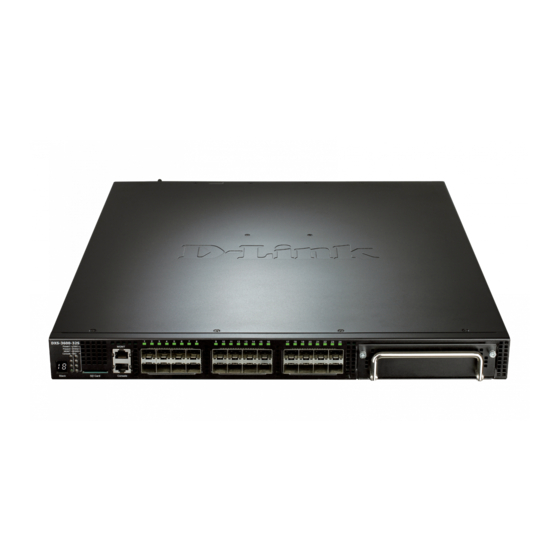
Page 9: Front Panel Components
DXS-3600 Series 10GbE Layer 2/3 Switch Hardware Installation Guide MIB, OSPFv2 MIB, VRRP MIB, Private MIB, Entity MIB. Front Panel Components The front panel of the switch consists of LED indicators, an SD card slot, an Out-Of-Band Management port (MGMT), a Console port, SFP+ ports and an open module slot. -
Page 10: Led Indicators
DXS-3600 Series 10GbE Layer 2/3 Switch Hardware Installation Guide Figure 1-4 Front panel view of the DXS-3600-32S with EM-8T module Figure 1-5 Front panel view of the DXS-3600-32S with EM-4QXS module Figure 1-6 Front panel view of the DXS-3600-32S with EM-8XS module... - Page 11 DXS-3600 Series 10GbE Layer 2/3 Switch Hardware Installation Guide Description Power 1, Power 2 This LED will light solid green after the Switch has been powered on successfully. This LED will light solid orange if the Switch’s power supply fails.
-
Page 12: Rear Panel Description
DXS-3600 Series 10GbE Layer 2/3 Switch Hardware Installation Guide Rear Panel Description Located on the rear panel of the switch are two power supply module slots and three fan module slots. One power supply module and three fan modules are included in the package for this switch. Any additional power supply module or fan module needs to be bought separately. -
Page 13: Side Panel Description
DXS-3600 Series 10GbE Layer 2/3 Switch Hardware Installation Guide Side Panel Description Located on the side panels of the switch are heat and fan vents that are used to dissipate heat. Do not block these openings. Leave at least 4 inches of space at the rear and sides of the switch for proper ventilation. Be reminded that without proper heat dissipation and air circulation, system components might overheat, which could lead to system failure or even severely damage components. -
Page 14: Installation
DXS-3600 Series 10GbE Layer 2/3 Switch Hardware Installation Guide Installation Installation Guidelines Installing the Switch without a Rack Installing the Switch into a Rack Installing Transceivers into the Transceiver Ports Installing Power Modules into the Power Module Ports Installing Fan Modules into the Fan Module Ports... -
Page 15: Installing The Switch Into A Rack
DXS-3600 Series 10GbE Layer 2/3 Switch Hardware Installation Guide Installing the Switch into a Rack This section is used to guide the user through installing the switch into a switch rack. The switch can be mounted in a standard 19"(1U) rack using the provided mounting brackets. Use the following diagram as a guide. -
Page 16: Installing Power Modules Into The Power Module Ports
DXS-3600 Series 10GbE Layer 2/3 Switch Hardware Installation Guide normally used for a connection that spans greater distances. The maximum distance that the copper wiring connection can reach is 100 meters. Fiber optic connections can span over several kilometers. The figure below illustrates how to properly insert SFP+ transceivers into the switch’s SFP+ ports. -
Page 17: Installing A Dc Power Module
DXS-3600 Series 10GbE Layer 2/3 Switch Hardware Installation Guide Figure 2-5 Installing an AC Power Supply Module Figure 2-6 Installed AC Power Supply Module In addition, an optional second AC power supply module can be plugged into the second power supply module slot displayed above. -
Page 18: Installing Fan Modules Into The Fan Module Ports
DXS-3600 Series 10GbE Layer 2/3 Switch Hardware Installation Guide Figure 2-8 Connecting a DC Battery to the DC Power Supply Module The DC power and AC power of the device will back up each other immediately when one of the power sources fail. If both power sources fail, unplug the switch. - Page 19 DXS-3600 Series 10GbE Layer 2/3 Switch Hardware Installation Guide NOTE: The Power Modules all support a specific air-flow direction. This air-flow direction must be the same as the Fan Module installed. By default the air-flow direction of the Power Module and...
-
Page 20: Switch Connections
DXS-3600 Series 10GbE Layer 2/3 Switch Hardware Installation Guide Switch Connections Switch to End Node Switch to another Switch Switch Stacking Switch to a Server Switch to End Node End node is a generic name for edge networking devices that will be connected to this switch. Typical examples of end nodes are Personal Computers (PCs), Notebooks, Access Points, Print Servers, VoIP Phones and more. -
Page 21: Switch Stacking
DXS-3600 Series 10GbE Layer 2/3 Switch Hardware Installation Guide Figure 3-2 Connecting a Switch to another switch by means of SFP/SFP+ Switch Stacking The DXS-3600-32S and DXS-3600-16S supports stacking 4 switches together while being managed by one IP address through Telnet, the Web User Interface, the RJ45 console port or through SNMP. This cost effective switch provides an affordable solution for administrators to upgrade their networks using either the DXS-3600-EM-Stack or the DXS-3600-EM-4QXS modules to scale and stack the switches. - Page 22 DXS-3600 Series 10GbE Layer 2/3 Switch Hardware Installation Guide Figure 3-4 Duplex Ring physical stack using the DXS-3600-EM-Stack module The DXS-3600-EM-4QXS module (sold separately) uses the last two QSFP+ ports to make the following stacking topologies. The figure below illustrates how switches can be stacked in a Duplex Chain formation using the DXS-3600-EM-4QXS module.
-
Page 23: Switch To A Server
DXS-3600 Series 10GbE Layer 2/3 Switch Hardware Installation Guide Figure 3-6 Duplex Ring physical stack using the DXS-3600-EM-4QXS module Switch to a Server When configuring a network, users will most likely have to add a server or two to this switch. Generally, any port on this switch can be used to connect to a server, as they all operate at a maximum speed of one 10Gbps. -
Page 24: Switch Management
DXS-3600 Series 10GbE Layer 2/3 Switch Hardware Installation Guide Switch Management Management Options Connecting to the Console Port Connecting using SNMP Connecting using the Web User Interface Management Options This switch provides multiple access platforms that can be used to configure, manage and monitor networking features available on this switch. - Page 25 DXS-3600 Series 10GbE Layer 2/3 Switch Hardware Installation Guide Set the terminal emulation software as follows: Select the appropriate serial port (COM1 or COM2). Set the data rate to 115200 baud. Set the data format to 8 data bits, 1 stop bit, and no parity.
-
Page 26: Connecting To The Switch For The First Time
DXS-3600 Series 10GbE Layer 2/3 Switch Hardware Installation Guide Boot Procedure V1.10.009 ------------------------------------------------------------------------------- Power On Self Test ........100 % MAC Address : 00-00-00-11-22-33 H/W Version : B1 Please Wait, Loading V2.40.038 Runtime Image ....100 % UART init .......... -
Page 27: Configuring The Ip Address
DXS-3600 Series 10GbE Layer 2/3 Switch Hardware Installation Guide Switch>enable Switch#configure terminal Switch(config)#username NewUser password 12345 Switch(config)#username NewUser privilege 15 Switch(config)#line console Switch(config-line)#login local Switch(config-line)#end Switch# Figure 4-5 To create a user account In the example above: 1. At the CLI command prompt, enter the enable command to enter the Privileged EXEC Mode. Press Enter. - Page 28 The SNMP agent decodes the incoming SNMP messages and responds to requests with MIB objects stored in the database. The SNMP agent updates the MIB objects to generate statistics and counters. D-Link provides a professional network management software package, called D-View 6.0 that uses SNMP to connect, ®...
-
Page 29: Traps
DXS-3600 Series 10GbE Layer 2/3 Switch Hardware Installation Guide Switch#configure terminal Switch(config)#snmp Switch(config)#show snmp community Community: public Access: read-only View: CommunityView Community: private Access: read-write View: CommunityView Total Entries:2 Switch(config)# Figure 4-8 To view the SNMP community strings SNMPv3 uses a more sophisticated authentication process that is separated into two parts. -
Page 30: Logging Onto The Web Manager
DXS-3600 Series 10GbE Layer 2/3 Switch Hardware Installation Guide Logging onto the Web Manager To access the Web User Interface the user simply runs the standard web browser and enter the Switch’s IP address into the address bar of the browser and press the ‘Enter’ key. By default, the Management port, located just above the Console port, can be accessed using the IP address of 192.168.0.1/24. - Page 31 Switch. This area displays the Switch’s ports and expansion modules. It also shows port activity based on a specific mode. Some management functions, including port monitoring are accessible from here. Click the D-Link to go to the D-Link website. AREA 2 This area displays a file explorer-type menu tree of all configurable options.
-
Page 32: Appendix A - Technical Specifications
DXS-3600-16S: Supports 4 stacking units with EM-4QXS modules via the last two ports. Virtual Stacking / Clustering: Support D-Link Single IP Management v1.61 Use a single IP to manage the virtual stack with up to 32 D-Link Layer 2/3 switches. Performance Specifications Switch Capacity DXS-3600-16S: 480Gbps DXS-3600-32S: 960Gbps DXS-3600-16S: 357.17Mpps... - Page 33 DXS-3600 Series 10GbE Layer 2/3 Switch Hardware Installation Guide Performance Specifications 160G (Bi-direction) via EM-4QXS module Environmental Specifications Temperature Operating: 0° to 45°C (32° to 113°F) Storage: -40° to 70°C (-40° to 158°F) Operating: 0% to 95% RH, Non-condensing...
- Page 34 DXS-3600 Series 10GbE Layer 2/3 Switch Hardware Installation Guide Port Specifications DEM-432XT-DD (10GBASE-LR, 10km (DDM) DEM-433XT (10GBASE-ER, 40km (w/o DDM) DEM-433XT-DD (10GBASE-ER, 40km (DDM) DEM-434XT (10GBASE-ER, 80km (w/o DDM) DEM-435XT (10GBASE-LRM (w/o DDM), 220m:OM1 & OM2 MMF, 300m: OM3 MMF) ...
- Page 35 DXS-3600 Series 10GbE Layer 2/3 Switch Hardware Installation Guide LED Indicators Location Color Status Description Light blinking Power supply module present, but AC or DC input is problematic. A reversed airflow power supply was inserted. Management Green Light on (Solid) Link present.
- Page 36 DXS-3600 Series 10GbE Layer 2/3 Switch Hardware Installation Guide LED Indicators Location Color Status Description LED Per Port Link/Act/Speed Green Light on (Solid) When there is a secure connection (10/100/1000Mbps) (or link) to 1000Mbps Ethernet device at any of the ports.
- Page 37 DXS-3600 Series 10GbE Layer 2/3 Switch Hardware Installation Guide LED Indicators Location Color Status Description Light blinking When there is reception or transmission of data occurring at 10/40Gbps. Amber Light on (Solid) When there is a secure connection (or link) to 1Gbps Ethernet device at any of the ports.
-
Page 38: Appendix B - Cables And Connectors
DXS-3600 Series 10GbE Layer 2/3 Switch Hardware Installation Guide Appendix B - Cables and Connectors Ethernet Cable When connecting the Switch to another switch, a bridge or hub, a normal cable is necessary. Please review these products for matching cable pin assignment. - Page 39 DXS-3600 Series 10GbE Layer 2/3 Switch Hardware Installation Guide Figure B-2 Console-to-RJ-45 Cable Contact Console (DB9/RS232) RJ-45 Not Used Not Used Not Used Not Used GND (shared) Not Used Not Used Not Used Not Used Not Used...
-
Page 40: Warranty & Technical Support
The customer must submit with the product as part of the claim a written description of the Hardware defect or Software nonconformance in sufficient detail to allow D-Link to confirm the same, along with proof of purchase of the product (such as a copy of the dated purchase invoice for the product) if the product is not registered. - Page 41 D-Link Corporation/D-Link Systems, Inc., as stipulated by the United States Copyright Act of 1976 and any amendments thereto. Contents are subject to change without prior notice. Copyright 2004 by D-Link Corporation/D-Link Systems, Inc.
- Page 42 Product Registration Register your D-Link product online at http://support.dlink.com/register/ Product registration is entirely voluntary and failure to complete or return this form will not diminish your warranty rights.
- Page 43 This guide is only for initial configuration. Please refer to the user manual to learn more or visit http://www.mydlink.com for more information. Also feel free to contact us. U.S. and Canadian customers can contact D-Link Technical Support through our website. http://support.dlink.com Canada...
- Page 44 Europe customers TECHNICAL SUPPORT TECHNISCHE UNTERSTÜTZUNG ASSISTANCE TECHNIQUE ASISTENCIA TÉCNICA SUPPORTO TECNICO TECHNISCHE ONDERSTEUNING POMOC TECHNICZNA TECHNICKÁ PODPORA TECHNICKÁ PODPORA dlink.com/support TECHNIKAI TÁMOGATÁS TEKNISK SUPPORT TEKNISK SUPPORT TEKNISK STØTTE TEKNINEN TUKI ASSISTÊNCIA TÉCNICA ΤΕΧΝΙΚΉ ΥΠΟΣΤΉΡΙΞΗ TEHNIČKA PODRŠKA TEHNIČNA PODPORA SUPORT TEHNIC ТЕХНИЧЕСКА...
- Page 45 Indonesia - www.dlink.co.id Malaysia - www.dlink.com.my Philippines - www.dlink.com.ph Vietnam - www.dlink.com.vn Korea customers Tel : +82-2-2028-1810 Monday to Friday 9:00am to 6:00pm Web : http://d-link.co.kr E-mail : g2b@d-link.co.kr New Zealand customers Tel: 0800-900-900 24/7 Technical Support Web: http://www.dlink.co.nz E-mail: support@dlink.co.nz...
- Page 46 08600 DLINK (for South Africa only) Monday to Friday 8:30am to 9:00pm South Africa Time Web: http://www.d-link.co.za E-mail: support@d-link.co.za D-Link Middle East - Dubai, U.A.E. customers Plot No. S31102, Jebel Ali Free Zone South, P.O.Box 18224, Dubai, U.A.E. Tel: +971-4-8809022...
- Page 47 Pakistan customers Islamabad Office: 61-A, Jinnah Avenue, Blue Area, Suite # 11, EBC, Saudi Pak Tower, Islamabad - Pakistan Tel.: +92-51-2800397, 2800398 Fax: +92-51-2800399 Karachi Office: D-147/1, KDA Scheme # 1, Opposite Mudassir Park, Karsaz Road, Karachi – Pakistan Phone: +92-21-34548158, 34326649 Fax: +92-21-4375727 Technical Support: +92-21-34548310, 34305069 General Inquiries: info.pk@dlinkmea.com...
- Page 48 Lebanon RMA center customers Dbayeh/Lebanon PO Box:901589 Tel: +961 4 54 49 71 Ext:14 Fax: +961 4 54 49 71 Ext:12 Email: taoun@dlinkmea.com Bahrain customers Technical Support: +973 1 3332904 Kuwait customers Technical Support: + 965 22453939 / +965 22453949 Türkiye customers Büyükdere Cad.
- Page 49 Обновления программного обеспечения и документация доступны на Интернет-сайте D-Link. D-Link предоставляет бесплатную поддержку для клиентов в течение гарантийного срока. Клиенты могут обратиться в группу технической поддержки D-Link по телефону или через Интернет. Техническая поддержка компании D-Link работает в круглосуточном режиме ежедневно, кроме...
- Page 50 Soporte Técnico Para Usuarios En Latino America Por favor revise el número telefónico del Call Center de su país en http://www.dlinkla.com/soporte/call-center Soporte Técnico de D-Link a través de Internet Horario de atención Soporte Técnico en www.dlinkla.com e-mail: soporte@dlinkla.com & consultas@dlinkla.com...
- Page 51 Clientes de Brasil Caso tenha dúvidas na instalação do produto, entre em contato com o Suporte Técnico D-Link. Acesse o site: www.dlink.com.br/suporte...
- Page 52 D-Link 友訊科技 台灣分公司 技術支援資訊 如果您還有任何本使用手冊無法協助您解決的產品相關問題,台灣地區用戶可 以透過我們的網站、電子郵件或電話等方式與 D-Link 台灣地區技術支援工程師 聯絡。 D-Link 免付費技術諮詢專線 0800-002-615 手機付費電話 (02)6600-0123#8715 服務時間:週一至週五,早上 9:00 到晚上 9:00 週六日及國定假日(不含農曆春節) 早上10:00到晚上7:00 網 站: http://www.dlink.com.tw 電子郵件: dssqa_service@dlink.com.tw 如果您是台灣地區以外的用戶,請參考D-Link網站,全球各地分公司 的聯絡資訊以取得相關支援服務。 產品保固期限、台灣區維修據點查詢,請參考以下網頁說明: http://www.dlink.com.tw 產品維修: 使用者可直接送至全省聯強直營維修站或請洽您的原購買經銷商。...
- Page 53 Pelanggan Indonesia Update perangkat lunak dan dokumentasi pengguna dapat diperoleh pada situs web D-Link. Dukungan Teknis untuk pelanggan: Tel: +62-21-5731610 Dukungan Teknis D-Link melalui Internet: Email : support@dlink.co.id Website : http://support.dlink.co.id 日本のお客様 この度は弊社製品をお買い上げいただき、誠にありがとうございます。 製品に同梱されている保証書の購入元にお問い合わせください。 中國客戶 辦公地址:北京市朝陽區將台路 5 號院 5 號樓...
- Page 54 8. What category best describes your company? Aerospace Engineering Education Finance Hospital Legal Insurance/Real Estate Manufacturing Retail/Chain store/Wholesale Government Transportation/Utilities/Communication System house/company Other________________________________ 9. Would you recommend your D-Link product to a friend? Don't know yet 10.Your comments on this product? __________________________________________________________________________________________ __________________________________________________________________________________________...