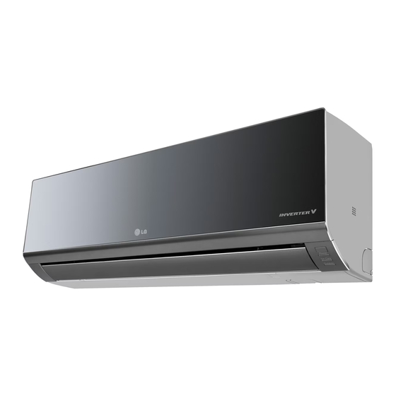
LG AMNW18GDCR0 Installation Manual
Type : wall mounted
Hide thumbs
Also See for AMNW18GDCR0:
- Installation manual (57 pages) ,
- Engineering product data book (94 pages) ,
- Owner's manual (43 pages)
Table of Contents
Advertisement
Quick Links
INSTALLATION MANUAL
AIR CONDITIONER
• Please read this installation manual completely before installing the product.
• Installation work must be performed in accordance with the national wiring
standards by authorized personnel only.
• Please retain this installation manual for future reference after reading it
thoroughly.
TYPE : WALL MOUNTED
*MFL67737207*
P/NO : MFL67737207
www.lg.com
Advertisement
Table of Contents

Summary of Contents for LG AMNW18GDCR0
- Page 1 • Please read this installation manual completely before installing the product. • Installation work must be performed in accordance with the national wiring standards by authorized personnel only. • Please retain this installation manual for future reference after reading it thoroughly. TYPE : WALL MOUNTED *MFL67737207* www.lg.com P/NO : MFL67737207...
- Page 2 TIPS FOR SAVING ENERGY TIPS FOR SAVING ENERGY Here are some tips that will help you minimize the power consumption when you use the air conditioner. You can use your air conditioner more efficiently by referring to the instructions below: •...
- Page 3 SAFETY PRECAUTIONS IMPORTANT SAFETY INSTRUCTIONS READ ALL INSTRUCTIONS BEFORE USING THE APPLIANCE. Always comply with the following precautions to avoid dangerous situations and ensure peak performance of your product WARNING It can result in serious injury or death when the directions are ignored CAUTION It can result in minor injury or product damage when the directions are ignored WARNING...
- Page 4 SAFETY PRECAUTIONS • Do not install the product on a defective installation stand. - It may cause injury, accident, or damage to the product. • Be sure the installation area does not deteriorate with age. - If the base collapses, the air conditioner could fall with it, causing property damage, product failure, and personal injury.
-
Page 5: Table Of Contents
TABLE OF CONTENTS TABLE OF CONTENTS IMPORTANT SAFETY IN- INSTALLATION STRUCTIONS Select the best Location Fixing Installation Plate Drill a Hole in the Wall INSTALLATION PARTS Flaring Work - Cut the pipes and the cable INSTALLATION TOOLS - Burrs removal - Putting nut on - Flaring work INSTALLATION MAP... -
Page 6: Installation Parts
INSTALLATION PARTS INSTALLATION PARTS Name Quantity Shape Installation plate 1 EA The feature can be changed according a type of model. Type "A" screw 5 EA Type "B" screw 2 EA Type "C" screw 2 EA Remote control 1 EA holder Screws for fixing panels are attached to decoration panel. -
Page 7: Installation Map
INSTALLATION MAP INSTALLATION MAP Installation plate Sleeve Bushing-Sleeve Putty(Gum Type Sealant) Bend the pipe as closely on the wall as possible, but be careful that it doesn't break. Vinyl tape (Wide) • Apply after carrying out a drainage test. • To carry out the drainage test, remove the air filters Saddle and pour water into the heat... -
Page 8: Installation
INSTALLATION INSTALLATION Select the best Location Fixing Installation Plate - There should not be any heat or steam near The wall you select should be strong and solid the unit. enough to prevent vibration - Select a place where there are no obstacles Mount the installation plate on the wall around of the unit. -
Page 9: Drill A Hole In The Wall
INSTALLATION Drill a Hole in the Wall Burrs removal 1. Completely remove all burrs from the cut - Drill the piping hole with a ø65mm hole core cross section of pipe/tube. drill. Drill the piping hole at either the right or the left with the hole slightly slanted to the 2. -
Page 10: Check
INSTALLATION Unlock the tubing holder from the chassis Handle and mount between the chassis and instal- lation plate in order to separate the bottom side of the indoor unit from the wall. Yoke Cone Copper pipe Clamp handle Red arrow mark Tubing Holder Check Compare the flared work with the figure... -
Page 11: Good Case
INSTALLATION Bad case Pull back the tubing holder. Remove pipe port cover and positioning - Following bending case from right to left di- the tubing rectly may cause damage to the tubing. Indoor unit back side view Pipe Port Left Right Tubing holder Backwards... -
Page 12: Right Side Piping
INSTALLATION Right side piping 3. When needed to extend the drain hose of indoor unit, assembly the drain pipe as shown on the drawing Tape Drain pipe Connecting cable Drain hose Indoor unit drain hose Connecting pipe Vinyl tape(narrow) Adhesive CAUTION Wrap the insulation material If the drain hose is routed inside the room... -
Page 13: Finishing The Indoor Unit Installation
INSTALLATION Finishing the indoor unit Connecting the Cables installation Indoor unit Mount the tubing holder in the original Connect the cable to the indoor unit by con- positon. necting the wires to the terminals on the con- Ensure that the hooks are properly seated trol board individually according to the outdoor on the installation plate by moving it left unit connection. -
Page 14: Checking The Drainage
INSTALLATION Checking the Drainage Do not make drain piping like the follow- ing. To check the drainage. Pour a glass of water on the evaporator. Do not raise Ensure the water flows through the drain hose of the indoor unit without any leak- age and goes out the drain exit. -
Page 15: Installation Of Filters
INSTALLATION Installation of filters Test Running Pull out the [Allergy free filter + Triple Fil- - Check that all tubing and wiring are properly ter] from the separately packed plastic bag. connected. Detach the two nitto tapes from the filter. - Check that the gas and liquid side service valves are fully open.


