
Related Manuals for Toshiba MML-UP0071H-E


Summary of Contents for Toshiba MML-UP0071H-E
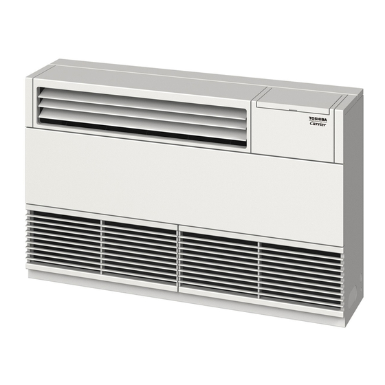
- Page 1 AIR CONDITIONER (MULTI TYPE) Installation Manual R410A For commercial use Indoor Unit Model name: <Floor Standing Cabinet Type> MML-UP0071H-E MML-UP0091H-E MML-UP0121H-E MML-UP0151H-E MML-UP0181H-E MML-UP0241H-E English...
-
Page 2: Table Of Contents
– 1 – Contents Original instruction Please read this Installation Manual carefully before installing the Air Conditioner. • This Manual describes the installation method of the indoor unit. 1 Precautions for safety ..........3 •... - Page 3 Toshiba Carrier Corporation or, alternatively, he or she has been instructed in such matters by an individual or individuals who have been trained and is thus thoroughly acquainted with the knowledge related to this work.
-
Page 4: Precautions For Safety
– 3 – Precautions for safety Warning indications on the air conditioner unit The manufacturer shall not assume any liability for the damage caused Warning indication Description by not observing the description of this manual. WARNING WARNING WARNING ELECTRICAL SHOCK HAZARD ELECTRICAL SHOCK HAZARD General Disconnect all remote... - Page 5 • When work is performed at heights, use a ladder which complies with Installation the ISO 14122 standard, and follow the procedure in the ladder’s • Install the air conditioner securely in a location where the base can instructions. Also wear a helmet for use in industry as protective gear sustain the weight adequately.
- Page 6 – 5 – Electrical wiring • If there is any kind of trouble (such as check code display has • Only a qualified installer (*1) or qualified service person (*1) is appeared, smell of burning, abnormal sounds, the air conditioner fails allowed to carry out the electrical work of the air conditioner.
- Page 7 CAUTION R410A refrigerant air conditioner installation • This air conditioner adopts the HFC refrigerant (R410A) which does not destroy ozone layer. • The characteristics of R410A refrigerant are; easy to absorb water, oxidizing membrane or oil, and its pressure is approx. 1.6 times higher than that of refrigerant R22.
-
Page 8: Accessory Parts
– 7 – Accessory parts Selection of installation place Avoid installing in the following places Select a location for the indoor unit where the cool or warm air will circulate evenly. Part name Q’ty Shape Usage Avoid installation in the following kinds of locations. Hand over to customers •... -
Page 9: Installation
Installation Installation space (Unit: mm) Reserve sufficient space required for installation or service work. CAUTION CAUTION <Space required for installation and servicing> Strictly comply with the following rules to prevent damage of the indoor units and human injury. 100 or more* 100 or more* •... - Page 10 – 9 – External dimensions Removing the panel before piping and electric wiring (Unit: mm) Remove the air intake grille (4 hooks at top and bottom each) Lower refrigerant piping port Remove the fan guard (4 screws) for piping work. (50 ×...
- Page 11 Installation of remote controller (sold separately) (1) Insert a flat-blade screwdriver or other tool into the slit (two places) in the bottom of the remote controller and remove the rear case. Install the wired remote controller sold separately as follows when mounting it on the main unit and using it. (2) Install the rear case onto the switch cover using two screws unfastened in RBC-ASCU11- (1) Unfasten the two screws fastened inside the air discharge port and remove the port by pushing it up.
-
Page 12: Drain Piping
– 11 – Drain piping Fixing the indoor unit to wall Wireless remote controller (sold separately) Fix the indoor unit to the wall as described below. CAUTION CAUTION Fix four M8 anchor bolts to the wall, as The signal receiving unit of indoor unit can receive a shown in the following figure. -
Page 13: Refrigerant Piping
Refrigerant piping Piping method The drain pipe and the refrigerant pipe can be connected to left, right, rear or bottom side arbitrarily according to Permissible piping length and the installation location. CAUTION CAUTION height difference Select a set knockout hole referring to the following figure. Use flare nuts that are included with the unit. -
Page 14: Electrical Connection
– 13 – Electrical connection Airtight test / Air purge, etc. Tightening connection For air tightness test, vacuum drying and adding CAUTION CAUTION refrigerant, refer to the Installation Manual attached WARNING to the outdoor unit. Do not apply excessive torque. Otherwise, the nut may crack depending on the conditions. - Page 15 Power supply wire and communication wires specifications <In the case of combining with outdoor units of Super Modular Multi System u series (SMMS-u)> Follow the wiring specifications in the table below even when units other than U series are mixed in the indoor units Power supply wire and communication wires are locally procured.
- Page 16 – 15 – Remote controller wiring <In the case of combining with outdoor units other than Super Modular Multi System u series (SMMS-u)> Control wiring between indoor units, and outdoor unit (L2, L3) • 2-core with non-polarity wire is used for the remote controller wiring and group remote controllers wiring. 1.25 mm²...
- Page 17 Wiring between indoor and outdoor units Wire connection Remote controller wiring Strip off approx. 9 mm the wire to be connected. NOTE REQUIREMENT Wiring diagram A wiring diagram below is an example for connection to SMMS-u series. For connecting to other outdoor unit •...
-
Page 18: Applicable Controls
– 17 – Applicable controls To secure better effect of Each time [ ] setting button is pushed, indoor unit numbers in the group control heating change cyclically. Select the indoor unit to Applicable controls setup REQUIREMENT change settings for. When it is difficult to obtain satisfactory heating due to (settings at the site) •... -
Page 19: How To Change The Discharge Port
How to change the discharge port Remote controller sensor When the indoor unit has a built-in remote Remove the two fixing screws inside of the The air discharging direction of the indoor unit has controller, the remote controller sensor is been set to forward direction as factory default. -
Page 20: Test Run
– 19 – Test run Upend the discharge port and mount it to the indoor unit. To mount the discharge port, hook the four hooks (two at rear and bottom side each). Before test run Wired remote controller Be sure to stop the air conditioner before making •... -
Page 21: Maintenance
Maintenance <Daily maintenance> Wireless remote controller ▼Cleaning of air filter Be sure to stop the air conditioner before cleaning of air <Overview of test run operations using the wireless Turn on the power of the air conditioner. filter. remote controller> When power is turned on for the first time after installation, it takes approx. -
Page 22: Troubleshooting
– 21 – Troubleshooting Periodic Maintenance For environmental conservation, it is strongly recommended that the indoor and outdoor units of the air conditioner in use be cleaned and maintained regularly to ensure efficient operation of the air conditioner. When the air conditioner is operated for a long time, periodic maintenance (once a year) is recommended. ... - Page 23 Check method On the wired remote controller, central control remote controller and the interface P.C. board of the outdoor unit (I/F), a check display LCD (Remote controller) or 7-segment display (on the outdoor interface P.C. board) to display the operation is provided.
- Page 24 – 23 – Check code Wireless remote controller Outdoor unit 7-segment display Sensor block display of receiving unit Check code name Judging device Wired remote controller display Auxiliary code Operation Timer Ready Flash 01: TE1 sensor 02: TE2 sensor TE1,TE2 or TE3 sensor trouble 03: TE3 sensor 01: TL1 sensor 02: TL2 sensor...
- Page 25 Check code Wireless remote controller Outdoor unit 7-segment display Sensor block display of receiving unit Check code name Judging device Wired remote controller display Auxiliary code Operation Timer Ready Flash — Model mismatch of indoor and outdoor unit — — Indoor unit centre unit duplicated Indoor unit —...
- Page 26 – 25 – Check code Wireless remote controller Outdoor unit 7-segment display Sensor block display of receiving unit Check code name Judging device Wired remote controller display Auxiliary code Operation Timer Ready Flash 01: Comp. 1 side 02: Comp. 2 side IPM short protection trouble Compressor inverter 03: Comp.
-
Page 27: Specifications
Model Weight (kg) Main unit 336 Tadehara, Fuji-shi, Shizuoka-ken 416-8521 JAPAN Cooling Heating MML-UP0071H-E MML-UP0091H-E TCF holder: TOSHIBA CARRIER EUROPE S.A.S Route de Thil MML-UP0121H-E 01120 Montluel FRANCE MML-UP0151H-E MML-UP0181H-E Hereby declares that the machinery described below: MML-UP0241H-E * Under 70 dBA... - Page 28 – 27 – WARNINGS ON REFRIGERANT LEAKAGE Important Check of Concentration Limit ▼NOTE 2 The room in which the air conditioner is to be installed requires a design that in the event of refrigerant The standards for minimum room volume are as follows. gas leaking out, its concentration will not exceed a set limit.
- Page 29 55-EN 56-EN – 28 –...
- Page 30 EB99841101...