Kenwood ProTalk Digital TK-3401D Quick Reference Manual
Hide thumbs
Also See for ProTalk Digital TK-3401D:
- Quick reference manual (148 pages) ,
- Service manual (38 pages) ,
- Instruction manual (36 pages)
Table of Contents
Advertisement
Quick Links
Advertisement
Table of Contents

Related Manuals for Kenwood ProTalk Digital TK-3401D


Summary of Contents for Kenwood ProTalk Digital TK-3401D
- Page 1 QUICK REFERENCE GUIDE UHF DIGITAL TRANSCEIVER TK-3401D © 2016 B5A-0035-10 (T)
-
Page 2: Operating Conditions
THANK YOU We are grateful you have chosen KENWOOD for your dPMR446 applications. This Quick Reference Guide covers only the basic operations of your dPMR446 (Digital Private Mobile Radio). Ask your dealer for information on any customized features they may have added to your radio. For using details instruction manual, refer to the following URL. -
Page 3: Notices To The User
Notice: The sign “Pb” below the symbol for batteries indicates that this battery contains lead. Firmware Copyrights The title to and ownership of copyrights for fi rmware embedded in KENWOOD product memories are reserved for JVC KENWOOD Corporation. - Page 4 • Ensure that there are no metallic items located between the transceiver and the battery pack. • Do not use options not specifi ed by KENWOOD. • If the die-cast chassis or other transceiver part is damaged, do not touch the damaged parts.
- Page 5 If an abnormal odor or smoke is detected coming from the transceiver, switch the transceiver power off immediately, remove the battery pack from the transceiver, and contact your KENWOOD dealer. • Use of the transceiver while you are driving may be against traffi c laws.
- Page 6 Information concerning the battery pack: The battery pack includes fl ammable objects such as organic solvent. Mishandling may cause the battery to rupture producing fl ames or extreme heat, deteriorate, or cause other forms of damage to the battery. Please observe the following prohibitive matters.
- Page 7 • Use only the specifi ed charger and observe charging requirements! If the battery is charged in unspecifi ed conditions (under high temperature over the regulated value, excessive high voltage or current over regulated value, or with a remodeled charger), it may overcharge or an abnormal chemical reaction may occur.
- Page 8 • Do not touch a ruptured and leaking battery! If the electrolyte liquid from the battery gets into your eyes, wash your eyes with fresh water as soon as possible, without rubbing your eyes. Go to the hospital immediately. If left untreated, it may cause eye-problems.
- Page 9 CONTENTS UNPACKING AND CHECKING EQUIPMENT ......1 PREPARATION ............2 ORIENTATION ............6 CHANNEL LIST ............8 UNPACKING AND CHECKING EQUIPMENT Carefully unpack the transceiver. If any of the items listed below are missing or damaged, fi le a claim with the carrier immediately.
-
Page 10: Installing/ Removing The Battery Pack
PREPARATION INSTALLING/ REMOVING THE BATTERY PACK ◆ Do not short the battery terminals or dispose of the battery by fi re. ◆ Never attempt to remove the casing from the battery pack. ◆ Install the battery pack after cleaning the battery pack contacts and the transceiver terminals. - Page 11 3 Slide a battery pack or a transceiver equipped with a battery pack into the charging slot of the charger. • Make sure the metal contacts of the battery pack mate securely with the charger terminals. • The indicator lights red and Indicator charging begins.
-
Page 12: Installing The Belt Clip
INSTALLING THE BELT CLIP If necessary, attach the belt clip using the two supplied M3 x 8 mm screws. Note: ◆ If the belt clip is not installed, its mounting location may get hot during continuous transmission or when left Belt clip sitting in a hot environment. -
Page 13: Installing The Optional Speaker/ Microphone
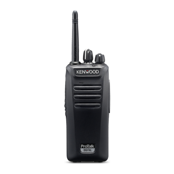
INSTALLING THE OPTIONAL SPEAKER/ MICROPHONE (OR HEADSET) Note: ◆ The transceiver is not fully water resistant when using a speaker/ microphone or headset. 1 Insert the speaker/ microphone (or headset) plugs into the speaker/ microphone jacks of the transceiver. 2 Place the Locking bracket over the speaker/ microphone (or headset) plugs so that the locking tabs insert into the transceiver grooves. - Page 14 ORIENTATION Microphone Speaker Antenna Battery pack Selector Rotate to change the operating channel. • Channel Annunciation: When changing channels, the transceiver will announce the newly selected channel number. (This can be deactivated by your dealer.) LED indicator Refer to the LED indicator status. {p. 7} Power switch/ Volume control Turn clockwise to switch the transceiver ON.
- Page 15 Side 1 key Press and hold this key to select the Digital mode and Analog mode. Side 2 key Press and hold this key to hear background noise. Release the key to return to normal operation. (Squelch Off Momentary) Speaker/ microphone jacks Insert the Speaker/ microphone or Headset plug into this jack.
-
Page 16: Channel List
CHANNEL LIST This transceiver allows you to reprogram each of the channels with different frequencies and ID (Digital)/ QT/DQT (Analog) settings. The table below lists the default channel settings. Digital Analog Channel Frequency Frequency Number QT/DQT (MHz) (MHz) 446.103125 446.00625 94.8 Hz 446.109375 446.09375...