Table of Contents
Advertisement
Quick Links
Advertisement
Table of Contents
Troubleshooting

Related Manuals for Samsung AC140NN4SEC/TL


Summary of Contents for Samsung AC140NN4SEC/TL
-
Page 2: Table Of Contents
(For India only) For more information on safe disposal and recycling, visit our website www.samsung.com/in/support or contact our Helpline numbers - 1800 40 SAMSUNG (1800 40 7267864) 1800 5 SAMSUNG (1800 5 7267864) -
Page 3: Using Parts
Because the following operating instructions cover various models, the characteristics of your air conditioner may differ slightly from those described in this manual. If you have any questions, call your nearest contact center or find help and information online at www.samsung.com. Important safety symbols and precautions: WARNING Hazards or unsafe practices that may result in severe personal injury or death. - Page 4 Safety precautions FOR INSTALLATION CAUTION Install your appliance on a level and hard floor that can support its weight. Failing to do so may result in abnormal vibrations, noise, or problems with the product. FOR POWER SUPPLY WARNING When the circuit breaker is damaged, contact your nearest service center. Do not pull or excessively bend the power line.
- Page 5 FOR USING WARNING Do not touch the circuit breaker with wet hands. This may result in electric shock. Do not strike or pull the air conditioner with excessive force. This may result in fire, injury, or problems with the product. ...
- Page 6 Safety precautions FOR USING CAUTION Do not stand on top of the appliance or place objects (such as laundry, lighted candles, lighted cigarettes, dishes, chemicals, metal objects, etc.) on the appliance. This may result in electric shock, fire, problems with the product, or injury. ...
-
Page 7: Checking Before Use
Checking before use Operation ranges The table below indicates the temperature and humidity ranges the air conditioner can be operated within. Refer to the table for efficient use. OPERATIONAL TEMPERATURE MODE INDOOR HUMIDITY IF OUT OF CONDITIONS INDOOR OUTDOOR Condensation may occur on the indoor COOLING 21˚C to 32˚C 21˚C to 54˚C... - Page 8 Checking before use Tips on using air conditioner Here are some tips that you would follow when using your air conditioner. TOPIC RECOMMENDATION Cooling • I f current outside temperatures are much higher than the selected indoor temperature, it may take time to bring the inner temperature to the desired coolness. • A void drastically turning down the temperature. Energy is wasted and the room does not cool faster.
-
Page 9: Viewing The Parts
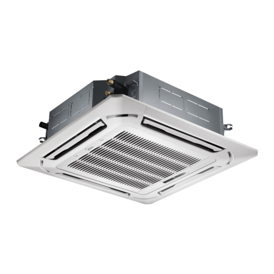
Viewing the parts Main parts Air flow blade Air intake Air filter (under the grille) Display Indicator Remote control sensor Filter reset indicator Timer indicator Removing frost indicator On/Off operation indicator • Y our air conditioner and display may look slightly different from the illustration shown above depending on your model. NOTE English... -
Page 10: Cleaning And Maintaining The Air Conditioner
Cleaning and maintaining the air conditioner Cleaning the exterior Wipe the surface of the unit with a slightly wet or dry cloth when needed. Wipe off dirt of odd-shaped area by using a soft brush. • D o not use Benzene or Thinner. They may damage the surface of the air conditioner and can CAUTION create a risk of fire. - Page 11 Open the blades on the left and right side of the Samsung logo. Press both of the levers and pull the hinge. Pull the green switch on the hinge part down and then press and pull the hinge part to remove grille downward.
- Page 12 Cleaning and maintaining the air conditioner If the air conditioner will not be used for an extended period of time, dry the air conditioner to maintain it in best condition. Dry the air conditioner thoroughly by operating in Fan mode for 3 to 4 hours and disconnect the power plug. ...
-
Page 13: Troubleshooting
Troubleshooting Refer to the following chart if the air conditioner operates abnormally. This may save time and unnecessary expenses. PROBLEM SOLUTION The air conditioner does not • B ecause of the protective mechanism, the appliance does not start operating immediately operate immediately after it to keep the unit from overloading. has been restarted. -
Page 14: Installation Parts
is sold or transferred. This manual explains how to install an indoor unit with a split system with two SAMSUNG units. The use of other types of units with different control systems may damage the units and invalidate the warranty. The manufacturer shall not be responsible for damages arising from the use of non compliant units. -
Page 15: Preparation For Installation
and with the instructions provided in the wiring scheme. Always verify that all connections comply with the standards applicable to the installation of air conditioners. Devices disconnected from the power supply should be completely disconnected in the condition of overvoltage category. ... -
Page 16: Deciding On Where To Install The Indoor Unit
Preparation for installation Accessories The following accessories are supplied with the indoor unit. The type and quantity may differ depending on the specifications. Pattern sheet Insulation cover Insulation cover Insulation drain Flexible hose clamp pipe A pipe B Flexible hose Cable-tie user &... - Page 17 Thickness: more than 10mm Indoor Unit 530x 140 530x 140 580x 140 AC071NN4SEC 435x140 830x830 530x224 530x224 580x224 AC100NN4SEC 435x224 830x830 530x 224 530x 224 580x 224 AC140NN4SEC 435x224 830x830 Insulate the end of the pipe and some curved area by using separate insulator. ...
- Page 18 Deciding on where to install the indoor unit Drawing of the indoor unit Unit : mm 890~910 (Celling opening) 735 (Suspension position) Sub duct connection MODEL AC100NN4SEC AC071NN4SEC AC140NN4SEC Net dimension 840×204×840 840×288×840 Net weight 15.0 18.0 Liquid pipe connection 1/4"(6.35) 3/8"(9.52) Gas pipe connection...
-
Page 19: Indoor Unit Installation
Indoor unit installation When deciding on the location of the air conditioner with the owner, the following restrictions must be taken into account. 1. Determine the position of the pipe and drain hose hole as seen in the picture and drill the hole with an inner diameter of 65mm so that it slants slightly downwards. -
Page 20: Purging The Unit
Purging the unit From factory the unit is supplied and set with a pre-charge of nitrogen gas. (insert gas) Therefore, all insert gas must be purged before connecting the assembly piping. Unscrew the pinch pipe at the end of each refrigerant pipe. Liquid refrigerant port RESULT : All inert gas escapes from the indoor unit. -
Page 21: Cutting/Flaring The Pipes
Cutting/Flaring the pipes 1. Make sure that you have the required tools available. (pipe cutter, reamer, flaring tool and pipe holder) 2. If you wish to shorten the pipes, cut it with a pipe cutter, taking care to ensure that the cut edge remains at a 90° angle with the side of the pipe. -
Page 22: Performing Leak Test & Insulation
Performing leak test & insulation Leak test To identify potential gas leaks on the indoor unit, inspect the connection area of each refrigerant pipe using a leak detector for R410A. Before recreating the vacuum and recirculating the refrigerant gas, it is advisable to pressurize the whole system with nitrogen (using a cylinder with pressure reducer) at a pressure above 40 bar in order to immediately detect leaks on the refrigerant fittings. - Page 23 Insulation Type (Heating/Cooling) Pipe Pipe size Standard [30°C, less than 85%] High humidity [30°C, over 85%] Remarks EPDM, NBR Ø6.35 ~ Ø9.52 Liquid pipe Ø12.7 ~ Ø19.05 Ø6.35 Internal temperature is Ø9.52 higher than 120°C Ø12.70 pipe Ø15.88 Ø19.05 When installing insulation in places and conditions below, use the same insulation that is used for high humidity condi- tions.
-
Page 24: Drainpipe And Drain Hose Installation
Drainpipe and drain hose installation 1 Push the supplied drain hose as far as possible over the drain socket. 2 Tighten the metal clamp as shown in the picture. 3 Wrap the supplied large sealing pad over the metal clamp and drain hose to insulate and fix it with clamps. 4 Insulate the complete drain piping inside the building (field supply). - Page 25 Performing leak test 1. Check the leak test at the connection part of the flexible hose and the distributing pipe (PVC). Water leakage check part 1) Connect a general hose to the connection part of the flexible hose of the indoor unit, and pour in some water.
-
Page 26: Connecting The Connection Cord
Connecting the connection cord • A lways remember to connect the refrigerant pipes before performing the electric connections. When disconnecting the system, always disconnect the electric cables before disconnecting the refrigerant pipes. • A lways remember to connect the air conditioner to the grounding system before performing CAUTION the electric connections. The indoor unit is powered by the outdoor unit by means of a H07 RN-F connection cable (or a more power model), with insulation in synthetic rubber and jacket in polychloroprene(neoprene), in accordance with the requirements of standard EN 60335-2-40. -
Page 27: Extending The Power Cable
Extending the power cable 1. Prepare the following tools. Tools Crimping pliers Connection sleeve (mm) Insulation tape Contraction tube (mm) Spec MH-14 20xØ6.5(HxOD) Width 19mm 70xØ8.0(LxOD) Shape 2. As shown in the figure, peel off the shields from the rubber and wire of the Power cable power cable. - Page 28 Extending the power cable 5. Wrap it with the insulation tape twice or more and position your contraction tube in the middle of the insulation tape. Three or more layers of insulation are required. f Method 1 f Method 2 Insulation tape Insulation tape 40 mm...
-
Page 29: Setting An Indoor Unit Address And Installation Option
Setting an indoor unit address and installation option Set the indoor unit installation option with remote controller. The procedure of option setting Option setting mode Entering mode for setting option Mode change High Temp Button High Fan Button Low Fan Button Low Temp Button Step 1. - Page 30 Setting an indoor unit address and installation option Option setting Status 1. Setting SEG2, SEG3 option Press Low Fan button(∨) to enter SEG2 value. Press High Fan button(∧) to enter SEG3 value. SEG2 SEG3 Each time you press the button, … will be selected in rotation. 2.
- Page 31 Option setting Status 13. Setting SEG16, SEG17 option Press Low Fan button(∨) to enter SEG16 value. Press High Fan button(∧) to enter SEG17 value. SEG16 SEG17 Each time you press the button, … will be selected in rotation. 14.
- Page 32 Setting an indoor unit address and installation option Setting an indoor unit address (MAIN/RMC) 1. Check whether power is supplied or not. f When the indoor unit is not plugged in, there should be additional power supply in the indoor unit. 2.
- Page 33 Setting an indoor unit installation option (suitable for the condition of each installation location) 1. Make sure power is ON to the outdoor unit. 2. The panel display should be connected to the indoor unit to receive option settings. 3. Set the installation option according to the installation requirements of the air conditioner. f The default indoor unit installation option setting is “020000-100000-200000-300000”.
- Page 34 Setting an indoor unit address and installation option Option SEG19 SEG20 SEG21 SEG22 SEG23 SEG24 Wireless controller Heating setting Explanation PAGE address compensation Indication Details Indication Details Indication Details 0 or 1 Indoor 1 Disuse RESERVED RESERVED RESERVED Setting/ Indoor 2 Details 2 °C Indoor 3...
-
Page 35: Troubleshooting
Troubleshooting LED lamp display Operation Defrost Timer Filter Abnormal conditions Remarks Error of temperature sensor in the indoor unit (Open/ Short) Error of EVA IN, OUT sensor in the indoor unit(Open/ Short) Error of fan motor in the indoor unit Error of outdoor sensor (outdoor temp./cond/discharge) No communication for 2 minutes between indoor and... - Page 36 Troubleshooting Wired remote control If an error occurs, is displayed on the wired remote control. If you would like to see an error code, press the Test button. Display Explanation Remark Compressor down due to protection control of the discharge temperature sensor Control due to the condenser temperature sensor when cool- ing mode...
- Page 37 QUESTIONS OR COMMENTS? COUNTRY CALL OR VISIT US ONLINE AT 1800 40 SAMSUNG (1800 40 7267864) (Toll-Free) INDIA www.samsung.com/in/support 1800 5 SAMSUNG (1800 5 7267864) (Toll-Free) 16600172667 (Toll Free for NTC Only) NEPAL www.samsung.com/support 9801572667 (Toll Free for Ncell users)
- Page 38 Air conditioner User&Installation manual ACNN4SEC • Thank you for purchasing this Samsung air conditioner. • Before operating this unit, please read this manual carefully and retain it for future reference.