LG LRH7080D Series Owner's Manual
Hybrid digital video recorder
Hide thumbs
Also See for LRH7080D Series:
- Owner's manual (94 pages) ,
- Owner's manual (2 pages) ,
- Owner's manual (59 pages)

Related Manuals for LG LRH7080D Series


Summary of Contents for LG LRH7080D Series
- Page 1 OWNER’S MANUAL Hybrid Digital Video Recorder Please read this manual carefully before operating your set and retain it for future reference. MODELS LRH7160D Series LRH7080D Series *MFL67849056* 1512 (V8.0)
-
Page 3: Safety Information
This lightning flash with arrowhead symbol within an equilateral triangle is intended to alert the user to the presence of LG Electronics hereby declares that this/ uninsulated dangerous voltage within the these product(s) is/are in compliance product’s enclosure that may be of sufficient... - Page 4 ‘damaged’ while playing a recording stored inside the system’s HDD, it must be replaced with a new one. Ask for an engineer’s assistance for HDD replacement from your dealer. LG Electronics is not responsible for deleted data caused by user mishandling. •...
- Page 5 In order to maintain stable system performance, have your system checked regularly by the service center. LG Electronics is not held responsible for system breakdown caused by user mishandling. There is a risk of explosion if a battery is replaced by an incorrect type. Dispose of used batteries according to the instructions.
-
Page 6: Table Of Contents
Contents Contents Main Monitor Screen Moving the Channel's Position Selecting the Main Monitor screen mode Selecting the Spot Monitor screen mode Grouping channel PTZ Camera Control Using the Digital Zoom function Export the recorded data Viewing the System Log List Safety Information Viewing System Information Configuration menu... - Page 7 Contents Notification Supported IP Camera Audio/Video Codec Mail Time zones Emergency Factory Default Configuration Settings SNMP Recording Time Table (250GB HDD) Output IP Live/Playback Specifications Buzzer Specifications User settings Group Authority User Setup Wizard settings Step 1 Step 2 Step 3 Step 4 Step 5 Operation...
-
Page 8: Preparation
Up to 480 IPS @ 704x480, LRH7160D Series • PTZ Control. NTSC Up to 240 IPS @ 704x480, LRH7080D Series Dome camera telemetry control (Dome OSD control). Up to 400 IPS @ 704x576, LRH7160D Series Up to 200 IPS @ 704x576, LRH7080D Series Accessories •... -
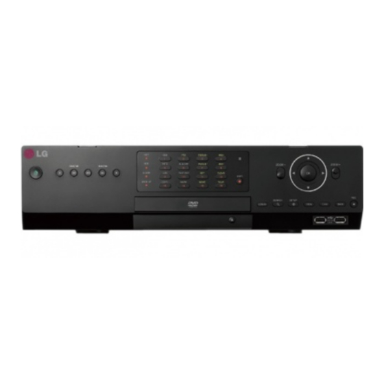
Page 9: Front Panel
SHIFT 10/0 BACK UP COPY MARK MOVE TOUR SEARCH SETUP LOG-IN VIEW BACK o p q r s Front of the LRH7080D series FOCUS+ IRIS+ INFO ALM.OFF FOCUS - IRIS - ALARM TEXT OFF CLEAR SHIFT BACK UP COPY MARK... - Page 10 Preparation Channel Buttons: You can input a number with channel buttons. You can also use the channel buttons for sub-function with SHIFT button (11 to 16 buttons of 8 channel DVR are used for sub-function without SHIFT button.). You should press the OK button after input the channel number when you select the applicable channel. •...
-
Page 11: Rear Panel
Preparation Rear Panel Rear of the LRH7160D series Rear of the LRH7080D series VIDEO INPUT: Connect the camera’s video output to these BNC connectors. LOOP OUT: The signal from VIDEO INPUT connector is looped out to this connector. RELAY-OUT Terminals: Output terminals for alarm (relay) signal. -
Page 12: Remote Control
Preparation Remote Control Button Description POWER (1) Turns DVR on or off. LOGIN Displays the User Log-In dialog box or logs out. Set the appropriate DVR system ID to operate via the IR Remote Controller when using the multiple DVR. Press the ID button then press the number button within 2 seconds to select the system ID of the DVR. -
Page 13: Installation
Installation Installation Connections Precautions • Depending on the camera and other equipment there are various ways to connect the unit. Please refer to the camera manual or manuals for other devices as necessary for additional connection information. • Be sure to switch off the camera before installation and connection. Basic Connection Overview Connect the coaxial-type cameras Connect the Monitor, DVR, VCR, or others. -
Page 14: Connecting Camera
Installation Connecting Camera Connecting Display device Connect the video output of your camera to the unit, using a This unit can be output simultaneously from the HDMI, VGA and standard 75 Ω video coaxial cable with BNC connector. SPOT OUT jack. The video signal connection between the DVR and LOOF OUT connector passes the video signal from VIDEO INPUT the monitor. -
Page 15: Connecting Audio Device
Installation HDMI Monitor connection Connect the unit to the HDMI monitor using a HDMI cable (Type A, High Speed HDMI Cable). HDMI Monitor connection MAIN SPOT USB Memory device Insert the memory device into the USB port. The system automatically recognizes the device. The system software can be easily upgraded using a USB memory device. -
Page 16: Connecting Atm/Pos
Installation Connecting ATM/POS Connecting Network Connect the ATM/POS unit to the ATM/POS port. You can control and monitor the system via network. With the remote control (monitoring), you can change the system configuration or monitor the image via network. After the ATM/POS device connection installation, check the network settings for the remote control and monitoring work. -
Page 17: Connecting Rs-485 Device
Installation Connecting RS-485 device Connecting LKD1000 controller Connect the LKD1000 controller to control the DVR. (Refer to the This DVR has two data terminals. Use this port to connect PTZ manuals of the LKD1000 controller for more details.) The LKD1000 cameras, DVRs or keypads (optional). - Page 18 Installation Alarm Output Sensor input connection Connect the alarm device to the alarm output. Alarm signal outputs when an event occur. Alarm output connection Alarm device Alarm device Terminal No. Description Alarm sensor Alarm sensor Ground Alarm Output 1 Alarm Output 2 Terminal No.
-
Page 19: Hdd Installation
Installation HDD INSTALLATION 6. When you turn the power of the unit on, the new HDD is detected and formatted automatically. CAUTION Note for Hard Disk Drive You should install the hard disk drive from 1 to 6 in order. The internal hard disk drive (HDD) is a fragile piece of equipment. -
Page 20: System Operation
Installation System Operation General Explanation of the Live Screen on the Main Monitor 1. Turn on the unit. System booting will commence. The LG logo image will be displayed on the main monitor during the system Main Monitor Screen booting. -
Page 21: Moving The Channel's Position
Installation Moving the Channel's Position You can control the PTZ Camera. (optional) You can change the camera channel's position in a split screen of You can use the video adjustment (Brightness, the Main Monitor. Contrast, Color) function. (Analog Channel Only) 1. -
Page 22: Selecting The Spot Monitor Screen Mode
3. Select a camera number for including group. 3. Select a screen mode. [Restore to Default] : Reset channels to ascending sort and change the [Split Mode] to 25 split. (LRH7080D series: 16 split) Screen split mode 4. Select group number on the drop-down list. - Page 23 Installation Preset Settings You can adjust the focus of a camera Preset position is the function to register camera monitoring manually. positions (preset positions) associated with position numbers. You can adjust the iris of a camera By entering the position numbers, you can move cameras to the manually.
-
Page 24: Using The Digital Zoom Function
You cannot control the other functions when the PTZ virtual • AVI LG: To playing AVI LG file, you have to install the LG DVR remote control is displayed. Codec. If you install the LG Network Client, do not need to install the LG DVR Codec. -
Page 25: Viewing The System Log List
Installation Viewing the System Log List NOTE To view the system log list: • Check the export device before you proceed. 1. Press the LOG button or click the icon in the system control • You can also use the COPY button on the front panel for bar. -
Page 26: Viewing System Information
Installation Configuration menu Viewing System Information To view system information: 1. Press the INFO button or click the icon in the system control bar. The system information window is displayed on the main The features and options of the DVR are configured through the monitor. -
Page 27: System Settings
Installation System settings Setting the Menu Using the Front Panel Buttons or Remote Control Buttons Remote Front Panel Description Control Properties Use these buttons to select the menu options or adjust the options value. SEARCH SETUP Select the option or confirm the LOG-IN VIEW BACK... -
Page 28: Tcp/Ip V4
IP address. • Host Name: Enter the host name you want to use. You can not use the “www”, “mail”, “http”, “ftp”, “com”, “lg”, “lge”, “lgddns”, “lgeddns”, “ddns” for host name. • Interface: Select a LAN port you want to use (Ethernet 0 or •... -
Page 29: Network Streaming
Installation Date/Time please check network connection. When you want to change DDNS host name If you want to change the registered host name to new one, follow as shown below. 1. Enter a new host name in the [Host Name] option. 2. -
Page 30: Controller
Installation Controller 8. To confirm the latest version, click the [Check now for update] button to visit http://www.lgecommercial.com NOTE • Do not turn the power off during the update process to prevent the malfunction. • Do not remove the external device or CD/DVD disc for update while the update is in progress. - Page 31 Installation 8. Select the [Start Backup] icon and press OK to start backup. NOTE 9. Exit the setup menu. You can check the backup status on the system control bar in backup progress. • You cannot stop the backup when the backup is in progress. •...
-
Page 32: Device Settings
Installation Device settings Settings for the PTZ cameras connected via the data port of the RS-485 terminal. Camera • Channel: Selects the desired channel to set the connected PTZ camera. • Ch: Displays the channel number. • Port: Selects the connected data port of the RS-485 terminal •... -
Page 33: Ip Device
Installation IP Device Audio/Sensor setting You can configure this option when you select to [LGE] on the [Driver] option. Select [Audio/Sensor] tab of the [Setup] window. Audio In: Click the check box if you want to send the audio from the microphone input connector. Audio Type: Select the codec when you send the audio from the microphone input connector. -
Page 34: Atm/Pos
Installation Compession (AXIS only): Enter the compression ratio of 6. Click the check box of confirmed cameras. Selected cameras are video. The lower value you set up, the higher definition registered channel in order. picture you get. 7. Click the [CLOSE] button to exit the window. •... -
Page 35: Storage
You can view all the channels in sequence in the selected screen division mode. You cannot use sequence mode with the 16 split (LRH7080D series: 8 split). While the sequence mode condition, if you change the screen division mode, the sequence function will be canceled. -
Page 36: Video Adjustment
Installation Record settings Video Adjustment Adjust the brightness, contrast and color settings of each camera channel. You can see the settings screen from the preview windows. Normal Schedule Recording A Normal schedule recoding can be activated at preset times, in a repeating pattern on selected weekdays. -
Page 37: To Set A Recording Schedule For A Special Day (Special Schedule)
Installation 2. Select a recording mode. NOTE In case you set the motion recording setting on the channel of IP camera, the recording starts when Video content analysis event as well as Motion event is occurred. 3. Drag and drop with left button of the mouse to set the channel and time you want to record. -
Page 38: Copying The Recording Schedule
Installation Normal Settings concerning normal recording. 2. Enter the name of the special day. Use w/s/a/d to select the [Name] column and press OK. The virtual keyboard menu appears. • CH: Displays the channel number. 3. Use w/s/a/d to enter the necessary information for year, •... -
Page 39: Motion
Installation Motion Instant/Panic Settings concerning motion recording. Settings concerning instant/panic recording. • CH: Displays the channel number. • CH: Displays the channel number. • Resolution: Selects the recording resolution. • Resolution: Selects the recording resolution. • Quality: Selects the recording picture quality. •... -
Page 40: Event Settings
Installation Event settings Motion Sensor • Channel: Select the channel to set motion detection. • Sensitivity: Set the level of sensitivity for the created motion detection area. Sensitivity can be set from level 1 to 10 or OFF. • Relay Output: Select the number of the RELAY-OUT terminal for •... -
Page 41: Atm/Pos Data Format
Installation ATM/POS Data Format Event Popup The DVR can be set to react to text input from devices such as ATMs (Automated Teller Machines) and POS (Point of Sale; i.e., cash registers). This screen allows you to configure the DVR for your input device. -
Page 42: Emergency
Installation Mail Emergency • Notification: Mark up to be notified the unit's operating • Notification: Mark up to be notified the emergency agent about information according to notification settings by e-mail. the unit's operating information according to your notification settings. •... -
Page 43: Output
Installation Buzzer • Trap Community String: Specifies the SNMP trap community in which you want to enable this system (e.g. lgecommunity or Marks up when you want to activate the selected option. public). Output • Sensor: Makes a sound when a sensor occurs. •... -
Page 44: User Settings 69 Specifications
Setup, Search/Play, Export, PTZ, Power Off, Instant Record: Set the authority for the selected group. Mark up the option to activate it. • Main Channel/Spot Channel: Selects the channel to allow the operation for the group user. The LG logo is displayed on the covert channel(s). -
Page 45: Setup Wizard Settings
Installation Setup Wizard settings Step 2 Set date and time. The Setup Wizard appears on the screen when you turn on the unit for the first time or select [Setup Wizard] on the Setup menu. You can set the System name, display language, date, time, network settings, recording schedule and recording mode on the initial setup wizard. -
Page 46: Step 3
Installation Step 3 Step 5 Set network address for LAN ports. Set recording mode for the Continuous and Event recording. • Interface: Select a LAN port you want to use (Ethernet 0 or • Resolution: Selects the recording resolution. Ethernet 1). •... -
Page 47: Operation
Operation Operation Instant Recording NOTE • External recording devices can be used as copy areas for images recorded on the hard disk. It is impossible to record Images from a camera will be recorded on the built-in hard disk. images on the external recording devices directly. Ensure all the cameras are connected and that time and date have •... -
Page 48: Instant Playback
Operation Instant Playback 7. Press ad (Play) button or click button to start playback. The picture(s) is (are) displayed on the main monitor. 8. Press STOP (Z) to stop playback and return to the search menu. 9. Press BACK repeatedly to exit the [Date/Time] menu. It is possible to play a recorded image without stopping recording. -
Page 49: Bookmark/Protect Search
Operation ATM/POS Search • OK: Selects the column or confirms the setting. 5. Use w/s/a/d button to select the channel and press OK Search the recorded text information by ATM/POS device. button to confirm the selection. If you want to select the all This function is available with backup data of the internal or external channels, marks up the [Select All] option. -
Page 50: Export Search
Operation Export Search Smart Search Searches an exported data in the external device or internal You can be searched the recorded data by specifying the motion DVD-ROM device. detection conditions. If you want to use this function, you have to connect the external device or insert the CD/DVD disc with exported data otherwise the warning message will be displayed. -
Page 51: Functions Available During Playback
Operation Functions Available During Playback Button Function FOCUS+ IRIS+ Playback Remote Control Front panel Control Menu INFO ALM.OFF FOCUS - IRIS - Stops playback. ALARM TEXT OFF CLEAR SHIFT 10/0 INFO ALM.OFF BACK UP COPY MARK MOVE TOUR Pauses playback. ALARM TEXT OFF FOCUS+... -
Page 52: Using The Playback Control Menu
Operation Using the playback control menu Using the Protect function You can use various playback function using playback control menu. This function allows you to protect the recorded data against being automatically overwritten. 1. Play a data recorded. Playback control menu appears at the bottom of the screen. How to select Protect section. -
Page 53: Troubleshooting
Check the power cable on the camera is connected correctly. displayed on the screen but the camera images are not Check there is no problem with the video cable connection between the camera and the LG DVR displayed. system. Turn off the DVR system and turn it on again. - Page 54 Troubleshooting Symptoms Cause & Solution Check the audio recording option is correctly set for the camera you wish to record audio. Audio data recorded with Check the speaker and audio (line input) on the rear of system are connected correctly. video data is not playing.
- Page 55 Troubleshooting Symptoms Cause & Solution E-mail reception failed without SMTP server setting. • Make sure the network is correctly set. • Make sure the mail address is input correctly. • Check the spam mail setting of the input mail address. (If you set the spam mail, some mails are deleted automatically or classified in the spam mail box) •...
-
Page 56: Appendix
Appendix Appendix Recommended Devices Recommended USB Memory list Maker Model Name Capacity LG Electronics XTICK SPIN LG Electronics XTICK UF1 32 G Lexar Jump Drive Memorive TRANSCEND 16 G SKYDRV SANDISK Cruzer 16 G Samsung Electronics SUM-LSB8 Samsung Electronics SUM-PSB... -
Page 57: Supported Function List For Device
Appendix Supported function list for device Device Instant backup Schedule backup Export Configuration Import/Export CD/DVD USB memory USB HDD E-SATA HDD NOTE If you use a USB memory stick or USB HDD for configuration import/export you must disconnect the other external USB devices. Supported PTZ Camera list Pan/Tilt Zoom... - Page 58 Appendix Time zones Timezone Timezone name Timezone Abbreviation Eniwetok, Kwajalein -12:00 Midway Island, Samoa -11:00 Hawaii -10:00 Alaska -09:00 -08:00 Pacific Time (US and Canada); Tajuana -08:00 -07:00 Mountain Time (US and Canada), Chihuahua, La Paz, -07:00 -06:00 Mazatlan, Arizona Central Time (US and Canada), Saskatchewan, Guadalajara, Mexico City, Monterrey, -06:00 -05:00...
- Page 59 Appendix Factory Default Configuration Settings Factory Default 1st level 2nd level 3rd level Default Value setting System Name NULL Language The option depends on the model. Button Beep Video Format NTSC or PAL Properties Resolution 1024*768 Configuration Import Configuration Export Factory Default Convert (LRH7160, LRN8240) Interface...
- Page 60 Appendix Resolution 352x240 (NTSC) / 352x288 (PAL) Network Streaming Quality STANDARD Frame Rate 7.5 (NTSC) / 6 (PAL) Profile Profile1 Date Current Date Time Current Time Date Format YYYY/MM/DD Time Format 12 HR Date/Time Time Zone The option depends on the model. Daylight Saving Daylight Saving Start JAN, 1st, SUN, 00...
- Page 61 Appendix Start Backup System Backup Erase Media Name CH 01 to CH 24 Camera Audio 01 to 16, OFF IP Enable ON, OFF Channel CH 01 Port NONE Control ID Protocol LG_MULTIX Baud Rate 9600 PTZ Test 9 to 24 Name CH 09 to CH 24 Model Name...
- Page 62 Appendix Overwrite Full Warning Auto Delete Storage Saving Device Storage Format E-SATA Insert Eject Channel Name Channel Status Channel FPS Channel Name (Spot) Font Size Position Display Main Dwell Time 2 SEC Sequence Spot Dwell Time 2 SEC Channel CH 01 Brightness Video Adjustment Contrast...
- Page 63 Appendix Resolution 704x480 (NTSC) / 704x576 (PAL) Quality STANDARD Sensor Frame Rate 15 (NTSC) / 12.5 (PAL) Prealarm 10 SEC Postalarm 10 SEC Resolution 704x480 (NTSC) / 704x576 (PAL) Quality STANDARD Motion Frame Rate 15 (NTSC) / 12.5 (PAL) Prealarm 10 SEC Record Postalarm...
- Page 64 Appendix Input Channel Transaction Start NULL Transaction End NULL ATM/POS Data Format Delimiter CARRIAGE RETURN Ignore String NULL Time Out 10 MIN Relay Output NONE Event Popup Spot Channel Sensor On Motion Detection Text In Notification Admin Password Changed Video Loss Power On/Off Disk Full Event...
- Page 65 Appendix SNMP Version NONE Port Community String public User NULL Authentication NONE SNMP Password NULL Privacy NONE Password NULL Trap IP Address NULL Event Trap Community String NULL Relay Off ALARM ACKNOWLEDGE System Alarm Out NONE Output HDD Fail Alarm Out NONE Video Loss Alarm Out NONE...
- Page 66 Appendix Recording Time Table (250GB HDD) Recording Time (Hr) Video (NTSC/PAL) Video + Audio (NTSC/PAL) Resolution Quality (NTSC/PAL) (8 CH, Video) (16 CH,Video) (8 CH, Video+Audio) (16 CH, Video+Audio) NTSC NTSC/PAL NTSC/PAL NTSC/PAL NTSC/PAL 30.0 25.0 699.75 711.50 349.88 355.75 538.15 545.07 269.07...
- Page 67 Appendix Recording Time (Hr) Video (NTSC/PAL) Video + Audio (NTSC/PAL) Resolution Quality (NTSC/PAL) (8 CH, Video) (16 CH,Video) (8 CH, Video+Audio) (16 CH, Video+Audio) NTSC NTSC/PAL NTSC/PAL NTSC/PAL NTSC/PAL 30.0 25.0 357.94 356.09 178.97 178.05 310.28 308.89 155.14 154.44 15.0 12.5 564.38 583.56...
- Page 68 Appendix Recording Time (Hr) Video (NTSC/PAL) Video + Audio (NTSC/PAL) Resolution Quality (NTSC/PAL) (8 CH, Video) (16 CH,Video) (8 CH, Video+Audio) (16 CH, Video+Audio) NTSC NTSC/PAL NTSC/PAL NTSC/PAL NTSC/PAL 30.0 25.0 240.47 237.62 120.24 118.81 217.98 215.63 108.99 107.82 15.0 12.5 379.82 388.56...
- Page 69 20fps x 2ch Over channel & resolution 8(I-Frame Only) 16(I-Frame Only) Specifications Model LRH7160D Series LRH7080D Series Analog Analog-IP Switch condition Analog-IP Switch condition Input - Basic : Analog 16ch + IP 8ch/4CIF - Basic : Analog 8ch + IP 8ch/4CIF or...
- Page 70 Appendix Up to 480 IPS @ 352x240 Up to 240 IPS @ 352x240 NTSC Up to 480 IPS @ 704x240 Up to 240 IPS @ 704x240 Up to 480 IPS @ 704x480 Up to 240 IPS @ 704x480 Recording Frame Rate (Analog) (/Second) Up to 400 IPS @ 352x288...