
Related Manuals for LG LE2116D


Summary of Contents for LG LE2116D
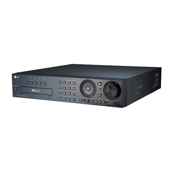
- Page 1 DIGITAL VIDEO RECORDER OWNER’S MANUAL MODEL: LE3116D LE3108D LE2116D LE2108D Before connecting, operating or adjusting this product, please read this owner’s manual carefully and completely.
- Page 2 Voltage Directive 2006/95/EC. accompanying the product. European representative : FCC WARNING: This equipment may generate or use LG Electronics Service Europe B.V. radio frequency energy. Changes or modifications to Veluwezoom 15, 1327 AE Almere, this equipment may cause harmful interference unless...
-
Page 3: Important Safety Instructions
IMPORTANT SAFETY INSTRUCTIONS CAUTION: PLEASE READ AND OBSERVE ALL WARNINGS AND INSTRUCTIONS IN THIS OWNER’S MANUAL. AND THOSE MARKED ON THE PRODUCT. RETAIN THIS BOOKLET FOR FUTURE REFERENCE. This product has been designed and manufactured to assure personal safety. Improper use can result in elec- tric shock or fire hazard. - Page 4 Ask for an engineer’s system. assistance for HDD replacement from your dealer. This may cause fire, electric shock, or serious LG Electronics is not responsible for deleted injury. data caused by user mishandling. • Check for any danger signs such as a moist floor, a loosened or damaged power cable, or an unstable surface.
- Page 5 • Placing the system near electronic devices such as a radio or a TV may cause the product to breakdown. • Do not disassemble the product without seeking assistance from LG Electronics. • Do not place any heavy object on the system.
-
Page 6: Table Of Contents
Contents SEARCH AND PLAYBACK ....42 PLAYBACK ............42 SEARCH .............43 INTRODUCTION ........7 Functions Available During Playback ....46 EXPORT ............47 Features ..............7 Front Panel ............8 CLIENT PROGRAM ......48 Accessories ............9 Rear Panel ............10 PC Requirements ..........48 Remote Control ...........11 Client Program Installation .........48 Connecting to the DVR ........48 HOOKUP AND SETTINGS .... -
Page 7: Introduction
Three USB 2.0 ports for backup interface. - Up to 200IPS@352 X 288: LE3108D PAL • Setup configuration export/import with - Up to 240IPS@352 X 240: LE2116D NTSC USB memory stick or network. - Up to 200IPS@352 X 288: LE2116D PAL •... -
Page 8: Front Panel
Front Panel x LE3116D/LE2116D k l mnopq x LE3108D/LE2108D k l mnopq Playback Control Buttons Channel Buttons - X: Pauses playback. You can input a number with channel buttons. - m/c, .: Search the recorded images in You can also use the channel buttons for sub- reverse or skip the recorded images. -
Page 9: Accessories
(7) IRIS - / (8) IRIS + JOG Dial Adjust iris position. Allows a forward or reverse frame search. In pause mode, plays recorded images (9) ALM.OFF frame by frame through rotation. Increases or Cancels alarm activation and returns the system decreases the options value. -
Page 10: Rear Panel
Rear Panel x LE3116D/LE2116D f g h j k l x LE3108D/LE2108D f g h j k l VIDEO INPUT AUDIO INPUT Connect the camera’s video output to these Connect the audio output of an external device. BNC connectors. SPOT-OUT (BNC Type Connector) LOOP OUT Connect to spot monitor or display device. -
Page 11: Remote Control
Remote Control MAIN M/C/> Forward searches the recorded Displays the MAIN menu to set images or skips the recorded the screen mode to full, 4, 6, 8, 9 images. or 16 screens. Number Buttons (0,1-9) SPOT To select the PTZ preset number, Enter SPOT mode to allow spot ID, or channel. -
Page 12: Hookup And Settings
HOOKUP AND SETTINGS Precautions • Depending on the camera and other equipment there are various ways to connect the unit. Please refer to the camera manual or manuals for other devices as necessary for additional connection information. • Be sure to switch off the camera before installation and connection. Basic Connection Overview Connect the coaxial-type cameras Connect the Monitor, DVR, VCR, or others. -
Page 13: Connecting The Rs-422/485 Device
Connecting the RS-422/485 Connecting Sensor Input and Device Alarm Output This DVR has two data terminals. Alarm terminals are used to connect the alarm devic- Use this port to connect PTZ cameras, DVRs or key- es such as sensors, door switches, etc. pads (optional). -
Page 14: Connecting The Usb Device
Alarm Output Network Connection Connect up to 4 separate alarms (LE3108/LE2108: 2 LAN Connection separate alarms) to the alarm output. Alarm signal output at an event occurrence. Connect the LAN port to an available 10/100 base-T port with a straight ethernet cable (not supplied). Rear of the DVR The NET indicator on the front panel will be lit. -
Page 15: Concerning The Internal Hard Disk Drive
Concerning the Internal Hard Installing or Replacing the Hard Disk Drive Disk Drive The internal hard disk drive (HDD) is a fragile piece of equipment. Please follow the guidelines below Installing the Hard Disk Drive when using the DVR to protect against possible HDD failure. - Page 16 5. Attach the hard disk mounting brackets with the • When installing 3 HDDs. screws. 1. Connect the SATA cable of the first HDD to 6. Connect the HDD power cable. the first SATA connector of the main board. It use for main system HDD. 2.
-
Page 17: Recommended Hdd
Replacing the Hard Disk Drive Recommended HDD The following HDD has been tested and compatibility is ensured. When you attach multiple HDDs use the Turn the power of the unit off and detach the power recommended HDDs. plug from the outlet. Maker Capacity Interface Model No. -
Page 18: System Operation
User User sounds to turn on the unit. System booting will View commence. The LG logo image will be displayed Live Video on the main monitor during the system booting. Alarm Off 2. When the booting is completed the live window will be displayed. -
Page 19: Selecting The Main Monitor Type
Selecting the main monitor type Note: You can select the monitor type by using the MAIN or You can select the main monitor type to display the SPOT button at anytime. If you change the monitor main screen on the power on condition. type, the system will be rebooted automatically. -
Page 20: General Explanation Of The Livescreen On The Main Monitor
General Explanation of the Live System Control Bar Screen on the Main Monitor - N (Normal partition): Used size/total size. - E (Event partition): Main Monitor Screen Used size/total size. Displays the current date and time. Display/hide playback control bar. Displays the setup menu. -
Page 21: Selecting Live Screen Mode
Selecting Live Screen Mode Spot Monitor You can select the live screen mode to full or 4-split Main Monitor screens on the spot monitor. You can select the live screen mode to display a full, 1. Press SPOT or Click the SPOT icon in the system 4-split, 6-split, 8-split, 9-split or 16-split screens on control bar. -
Page 22: Ptz Camera Control
PTZ Camera Control Exit Remove the PTZ virtual remote control. You can control the cameras connected via the data v/V/b/B port of RS-422/485 terminal. You must set the con- Use to pan/tilt the camera. figuration between the PTZ camera and the DVR. 1. - Page 23 Preset Settings To Tour The Preset Positions Preset position is the function to register camera You can tour all preset positions. monitoring positions (preset positions) associated 1. Press the TOUR button or Click the [TOUR] icon. with position numbers. All registered preset positions in the camera will By entering the position numbers, you can move be selected and the camera position image will be cameras to the preset positions.
-
Page 24: Viewing System Information
Viewing System Information Note: The system log list. To view system information: Log Message 1. Press INFO or click the INFO icon in the system Power On control bar. The system information window is displayed on Power Off the main monitor. Power Recovery Admin Login (Remote) Admin Logout (Remote) -
Page 25: Menu Configuration
Menu Configuration Setting the Menu Using the Front Panel Buttons or Remote Control Buttons The features and options of the DVR are configured through the menu. The operations of this unit can be set via a menu Arrow Buttons: displayed on the main monitor. You can select and Use these buttons to select the menu options or set the operational conditions by using the buttons on adjust the options value. -
Page 26: Camera Settings
DVR via DATA 2 port, you prevent operation by other users. If the covert should set the DVR ID number(1~16) on the sys- option is set to ON, “LG logo” is displayed on the tem setup menu. live window with POWER or NORMAL user. - Page 27 Frame Rate 704*576 1, 3, 5, 6 352*240 1, 3, 5, 7.5, 15, 20, 30 NTSC 704*240 1, 3, 5, 7.5, 15 LE2116D/LE2108D model 704*480 1, 3, 5, 7.5 Resolution Frame Rate 352*288 1, 3, 5, 6, 12.5, 20, 25 352*240 1, 3, 5, 7.5, 15...
-
Page 28: Schedule Settings
For each 1-hour cell block the recording method can 704*576 1, 3, 5, 6 be specified. The recording method for each block is shown in color for easy viewing. LE2116D/LE2108D model Resolution Frame Rate 352*240 1, 3, 5, 7.5, 15... - Page 29 To Set the Recording Schedule for a - Green+Blue (Continuous+Motion event record- ing): Recording starts automatically from the Typical Day of the Week preset time. When the motion is detected 1. Select a day of the week. within a designated time, change the continu- (Sun, Mon, Tus, Wed, Thu, Fri or Sat) ous recording mode to motion event recording mode and recording starts automatically.
- Page 30 b / B (or left/right mouse button): Changes • the value at the current position. 5. Use b / B / v / V to select [OK] button and press ENTER. The virtual keyboard menu appears. To Set a Recording Schedule for a Special Day 6.
-
Page 31: Display Settings
Note: Display Settings If the special day recording schedule is duplicated with the other recordings, only the special day record- ing is possible. Copying the Recording Schedule Copying from the Scheduled Data of the Channel You can copy the schedule data of the channel to the other channel(s) within the selected day of the week. -
Page 32: Event Settings
Spot Monitor Motion Dwell Time: You can set the channel sequence Channel: Select the channel to set motion detec- time to 2 SEC, 5 SEC, 10 SEC, 20 SEC, 30 SEC, tion. 40 SEC, 50 SEC, 60 SEC, 70 SEC, 80 SEC or 90 Sensitivity: Set the level of sensitivity for the cre- SEC. -
Page 33: Network Settings
Output options are dimmed and these options are not set. - OFF: Enter the network settings manually. IP Address: Enter an IP address using the virtual keyboard. Subnet Mask: Enter a subnet mask address using the virtual keyboard. Gateway: Enter the gateway address using the vir- tual keyboard. - Page 34 How to register DDNS host name When host name is properly changed, the changed host name will be displayed in With the DDNS function, you can easily use LG DVR. [Registered Host]. When you use the DDNS function for the first time after you purchased LG DVR 1.
- Page 35 Notification Mail Sensor On: Notification - ON: Sends an e-mail when a sensor has - ON: Notifies the user of unit operating information occurred. by e-mail according to notification settings. - OFF: Not used. - OFF: The notification function is not used. The mail options are dimmed.
-
Page 36: System Settings
Emergency Time Zone: Select your Time Zone. (For more details refer to Timezone table on page Daylight Saving: Set to ON to you use the daylight saving function. Daylight Saving Start: Select the Daylight Saving start time. Daylight Saving End: Select the Daylight Saving end time. - Page 37 Buzzer Password: Enter or change the password for the user using the virtual keyboard. You can use the password with number, special character or charac- ters. (Minimum 4 length, Maximum 8 length). Note: Remember the password. If you forget the password please contact an authorized service center or the store where you purchased the system.
- Page 38 Configuration Overwrite: - ALL: Overwrite recording is possible when the normal partition and event partition of HDD have fully recorded. - NORMAL PARTITION: Overwrite recording is possible for normal partition of HDD when the normal partition of HDD has fully recorded. - EVENT PARTITION: Overwrite recording is possible for event partition of HDD when the event partition of HDD has fully recorded.
- Page 39 Schedule Start: Set the schedule start date (A day Instant Backup of the week and time). 1. Connect the backup USB device or insert a Time Range Date: Enter the backup time range. recordable disk to the disc driver for backup. Enter the date you want to backup.
- Page 40 Daily/Weekly backup System 1. Connect the USB device for backup. You cannot use the CD or DVD writer for daily or weekly backup. 2. Select WEEKLY or DAILY on the schedule options. 3. Select the backup device. 4. Enter the date and/or time to start backup on the schedule start option.
-
Page 41: Recording
RECORDING Notes: • You can record instantly with the left mouse button. 1. Move the cursor to the desired channel screen Images from a camera will be recorded on the built-in on the main monitor. hard disk. 2. Click the recording type indicator with the left Note: mouse button and recording starts. -
Page 42: Search And Playback
SEARCH AND Instant Playback in POP (Picture over Picture) PLAYBACK Use the ZOOM +/- buttons to enlarge or reduce the PIP window as below. x1 size y x4 size y x9 size y Full screen size. PLAYBACK Instant Playback in PIP (Picture in Picture) It is possible to play a recorded image without stop- ping recording. -
Page 43: Search
SEARCH Date and Time Search Use to search recorded pictures by specifying date, The various search functions of this unit can be used hour and minute. to go to the beginning of the desired picture. This unit is equipped with 4 search functions. When the SEARCH button is pressed the search menu is displayed. - Page 44 Notes: Event Search • Recorded data shown on the time graph will be dis- Search a recorded picture by date and type of event. played in different colors depending on the record- ing type. - Green: Continuous recording. - Red: Sensor recording. - Blue: Motion-detection recording.
- Page 45 Smart Search 7. Select the recording data on the motion detect list then press PLAY, click [Play] or double click the Pictures recorded via motion detection can be selected data to start playback. searched by specifying the motion detection condi- The picture is displayed in the POP window of the tions.
-
Page 46: Functions Available During Playback
Functions Available During Playback Button System Remote Function Front panel Control Bar Control Stop playback. Pause playback. Jump to the beginning of the current data that was recorded on the same date. (press the button for more than 2 seconds.) Jump to the last 1 minute of the current data that was recorded on the same date. -
Page 47: Export
• You can also use the COPY button on the front panel for export function. LE3116D/LE2116D: Press SHIFT and then COPY button. LE3108D/LE2108D: Press COPY button only. • You can export the recorded data only in the live mode. -
Page 48: Client Program
CLIENT PROGRAM Connecting to the DVR Register the Site Name Client Program is the network program of the LG You should register a site name to control DVR by DVR. This manual is written based on LE3116D (16 the Client Program. - Page 49 Note: User Log-In In case of entering the server name instead of the 1. Select the registered site name and right click the IP Address. You should set up the DDNS configura- mouse. tion properly in the server. Please refer to the server 2.
-
Page 50: Main Screen Of Dvr Client Program
- Smart Search (See page 55) the play back recorded data of the selected • Remote Setup Mode channel. The save folder is “C:\LG Exported You can set the configuration of the unit. Files”. - Camera / Display (See page 55-57) •... -
Page 51: Live Mode
You can view the live window(s) in full screen mode. To return to the normal screen right click the mouse. 6. Sequence Icon View all the channels in sequence. You cannot use sequence mode with the 16 split. 7. Information Display Window 7. - Page 52 Using the Pan/Tilt/Zoom Function Displays Selected Preset Numbers You can control the PTZ cameras via the network. Number Buttons To input the preset number. To register preset positions. MOVE To move the camera to the preset position. CLEAR To delete a memorized preset position. TOUR To start a preset tour.
- Page 53 To Clear the Preset Position Using the Log View Function You can delete a memorized preset position. You can see the system log list of selected site names in the remote setup tab via the network. 1. Click the [CLEAR] icon. 2.
-
Page 54: Search Mode
Search Mode Using the Event Search function Search a recorded picture by date and event type. You can search the data of a selected site name in the remote setup tab via the network. Using the Date/Time Search function Use to search a recorded picture by specifying date, hour and minute. -
Page 55: Remote Setup Mode
Using the Smart Search function 7. Click the search icon. The smart search data is displayed. Picture recorded via motion detection can be searched by specifying the motion detection condi- tions. 1. Select the Smart Search tab. 8. Select the channel from the list. 2. - Page 56 1. Select a channel for settings. If you want to block a channel from other users, mark up the convert option. The marked up chan- nels are displayed “LG logo” on the live windows for POWER or NORMAL user. 2. Enter the new channel name.
- Page 57 Motion Recording Settings • Continuous: Recording starts automatically at the preset time. 1. Click the [Motion Recording] button. • Sensor: Recording starts automatically when The motion recording setting window appears. sensor occurs within a designated time. • Motion: Recording starts automatically when motion is detected within a designated time.
- Page 58 Special day Settings Event setup 1. Set the event options. • Sensor: Displays the number of the ALARM-IN terminal. • Sensor Type: The alarm state can be set to 1. Mark up the special day option. either N.O. (Normally Open) or N.C. (Normally 2.
-
Page 59: Network Setup
Network setup Notification Set the notification options. • Sensor On: Sends an E-mail when a sensor has been detected. • Video Loss: Sends an E-mail when a video sig- nal from the camera has stopped because of a cable disconnection or malfunction of a camera. •... - Page 60 System setup Log Out Auto User Logout: Setting the logout time. You can set the auto logout time to Off, 5 minutes, 10 minutes, 30 minutes or 60 minutes. Buzzer Settings Select the buzzer options. Button: Makes a sound when using the buttons. Sensor: Makes a sound when an sensor occurs.
-
Page 61: Remote Export Settings
The When the start date/time and end date/time initial save folder is "C:\LG Exported Files". If you are the same. want to change the exported data save folder, click the icon and select the new folder. -
Page 62: Additional Programs
ON, the system sends a message according to the settings of the notification options in the setup menu. (See page 35-36). 1. Double-click the [LG Emergency Agent] icon to start the emergency agent program. The Emergency icon is displayed in the system tray on the bottom right of the screen. -
Page 63: Export Viewer Program
Port Setting 3. Click [Yes] to delete the message. Export Viewer Program You can playback from the export data on the PC using this program. The export viewer program is saved automatically when you install the client pro- gram or export the data. 1. -
Page 64: Web Viewer Program
3. Press ENTER and then the Web viewer and the Playing Data Remote Login menu will be displayed. 1. Double click the [LG Export Viewer] icon on the PC or run the [LG Export Viewer.exe] file in the Export Viewer folder of the external USB device. - Page 65 Using the Web Viewer You can control the live image using the Web Viewer. 2. Use virtual remote control buttons to control the PTZ camera. For more details, refer to "Using the Pan/Tilt/Zoom Function" on page 52. Playback of Recorded Data Click to change the PTZ View mode or Live View mode.
-
Page 66: Reference
Check the monitor power cable is connected properly. Make sure the monitor is turned on. The system power is turned on but no Check the video output cable of the LG DVR is properly connected to the video data is dis- monitor. played on the moni- tor. - Page 67 Symptoms Resolutions Check the audio recording option is correctly set for the camera you wish to record audio. Audio data recorded with video data is Check the speaker and audio (line input) on the rear of system are con- not playing. nected correctly.
- Page 68 Symptoms Resolutions E-mail reception failed without SMTP server setting. • Make sure the network is correctly set. • Make sure the mail address is input correctly. • Check the spam mail setting of the inputted mail address. (If you set the spam mail, some mails are deleted automatically or classified in the spam mail box) •...
-
Page 69: Recommended Devices
Recommended Devices • Supported USB Memory list Maker Model Name Capacity LG Electronics XTICK Mini Slide / Slide 1G/2G/4G IOCELL CellDisk Swing 1G/2G/4G/8G Sony MicroVault 1G/2G/4G S100 / M100 / V210W 1G/2G/4G SANDISK Cruzer Micro 512M/1G TRANSCEND 1G/2G IMATION Flash Drive Nano / Icon... -
Page 70: Time Zones
Time zones Timezone Timezone name Timezone Abbreviation Eniwetok, Kwajalein -12:00 Midway Island, Samoa -11:00 Hawaii -10:00 Alaska -09:00 -08:00 Pacifi c Time (US and Canada); Tajuana -08:00 -07:00 Mountain Time (US and Canada), Chihuahua, La Paz, -07:00 -06:00 Mazatlan, Arizona Central Time (US and Canada), Saskatchewan, Guadalajara, -06:00 -05:00... -
Page 71: Factory Default Configuration Settings
Factory Default Configuration Settings Classification Detailed Items Default Setting LE3116D LE3108D 1st level 2nd level 3rd level LE2116D LE2108D Name CH 01~CH 16 CH 01~CH 08 Camera Covert Audio NONE, 01 ~ 04 NONE, 01~02 Channel CH 01 : Name... - Page 72 Classifi cation Detailed Items Default Setting LE3116D LE3108D 1st level 2nd level 3rd level LE2116D LE2108D Sensor Type N.O. Sensor Camera 01~16 01~08 Relay Output NONE, 01~04 None, 01~02 Channel CH 01 : Name Event Sensitivity Motion Relay Output NONE...
- Page 73 Classifi cation Detailed Items Default Setting LE3116D LE3108D 1st level 2nd level 3rd level LE2116D LE2108D Date (2008.01.01) Time Current Time Date Format (YYYY/MM/DD) Time Format 24 Hr (12 Hr) Date/Time Time Zone (GMT) Daylight Saving Daylight Saving Current Time...
-
Page 74: Recording Time Table (250Gb Hdd)
Recording Time Table (250GB HDD) Recording Time (Hr) Resolution FPS (NTSC/ Quality Video (NTSC/PAL) Video+Audio (NTSC/PAL) PAL) 8 ch 16 ch 8 ch 16 ch 30/25 275/220 138/110 251/201 125/100 20/20 285/228 143/114 259/207 130/104 15/12.5 416/333 208/167 363/290 181/145 Lowest 7.5/6 593/474... - Page 75 Recording Time (Hr) Resolution FPS (NTSC/ Quality Video (NTSC/PAL) Video+Audio (NTSC/PAL) PAL) 8 ch 16 ch 8 ch 16 ch 15/15 321/257 160/128 288/231 144/115 7.5/7.5 453/363 227/181 390/312 195/156 Lowest 571/457 285/228 475/380 237/190 642/514 321/257 523/418 261/209 1133/906 566/453 808/647 404/323...
-
Page 76: Specifications
Specifications LE3108D LE3116D Model LE2108D LE2116D Input Loop Through Video Output Composite Spot Input Audio Output Input Alarm Output Pre-Alarm Recording Up to 60 sec Up to 60 sec Up to 240 IPS @ 352x240 Up to 480 IPS @ 352x240...