Table of Contents
Advertisement
Quick Links
Advertisement
Table of Contents

Related Manuals for Huawei U8655N


Summary of Contents for Huawei U8655N
- Page 1 U8655N Maintenance Manual Issue Date 2012-09-27 HUAWEI TECHNOLOGIES CO., LTD.
- Page 2 Notice The purchased products, services and features are stipulated by the contract made between Huawei and the customer. All or part of the products, services and features described in this document may not be within the purchase scope or the usage scope. Unless otherwise specified in the contract, all statements, information, and recommendations in this document are provided "AS IS"...
-
Page 3: About This Document
Reviewed by Date Maintenance support team Approved by Date Service representative Change History Date Version Change Reason Revised Section Description Author 2012-02-20 V1.0 Released the first issue. R&D Issue 1.0 (2012-02-23) Huawei Proprietary and Confidential Copyright © Huawei Technologies Co., Ltd. -
Page 4: Table Of Contents
9.3.1 RF Failure ............................. 30 9.3.2 GPS ............................... 33 9.3.3 Wi-Fi/Bluetooth/FM Module ........................ 33 9.4 Peripheral Circuits ............................34 9.4.1 Display ..............................34 9.4.2 Camera ..............................37 Issue 1.0 (2012-02-23) Huawei Proprietary and Confidential Copyright © Huawei Technologies Co., Ltd. - Page 5 9.4.16 NFC ..............................54 10 Solder Points on the PCB and BGA Chip................59 11 Functional Tests......................... 64 11.1 MMI Test ..............................64 11.2 Voice Call Test .............................. 67 Issue 1.0 (2012-02-23) Huawei Proprietary and Confidential Copyright © Huawei Technologies Co., Ltd.
-
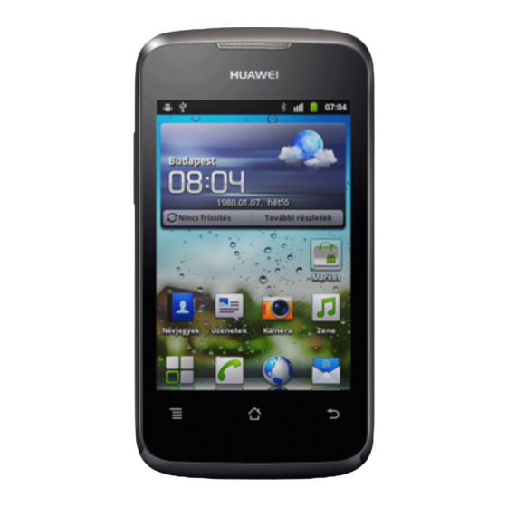
Page 6: Product Introduction
Product Introduction 1.1 Appearance 1.2 Specifications Category Description Dimensions (H x W x D) 116.9 mm x 61.4 mm x 12.2 mm Technical standard U8655N: W2100/W900, GSM850/900/1800/1900 Issue 1.0 (2012-02-23) Huawei Proprietary and Confidential Copyright © Huawei Technologies Co., Ltd. - Page 7 ≤ 104 dBm Static sensitivity Temperature Operating temperature: 0° C to +40° C Storage temperature: –20° C to +50° C Humidity Operating humidity: 5% to 95% RH Issue 1.0 (2012-02-23) Huawei Proprietary and Confidential Copyright © Huawei Technologies Co., Ltd.
-
Page 8: Applicable Scope And Precautions
2.1 Applicable Scope This document provides repair instructions for technicians at service centers authorized by Huawei. This maintenance manual is confidential and accessible to authorized service centers (ASCs) and authorized service providers (ASPs) only. While every effort has been made to ensure the accuracy of this document, errors may still exist. -
Page 9: Exploded View
Table 3-1 List of components in the exploded view drawing Item Quantity U8655N_Cover A assembly Touchscreen panel U8655N_Cover B assembly U8655N_Battery cover assembly U8655N_Volume key Issue 1.0 (2012-02-23) Huawei Proprietary and Confidential Copyright © Huawei Technologies Co., Ltd. - Page 10 Screw M1.4*3.5 Diversity antenna and Wi-Fi antenna Bluetooth antenna Main antenna Power key flexible flat cable (FFC) Receiver PCBA Volume key FFC Camera Speaker Battery NFC antenna Issue 1.0 (2012-02-23) Huawei Proprietary and Confidential Copyright © Huawei Technologies Co., Ltd.
-
Page 11: Components On The Pcba
U3201 RF connector U3202 RF switch can cause: Failure of this component Failure of this component W2100MHz transmission can cause: can cause: and reception failure. RF failure. RF failure. Issue 1.0 (2012-02-23) Huawei Proprietary and Confidential Copyright © Huawei Technologies Co., Ltd. - Page 12 U3801 WCDMA/GSM J901 IO connector transmission and Failure of this component reception chip can cause: Failure of this component Charging failure. can cause: data communication failure. RF failure. Issue 1.0 (2012-02-23) Huawei Proprietary and Confidential Copyright © Huawei Technologies Co., Ltd.
-
Page 13: Software Upgrade
Before the upgrade, NV items backup is performed (if the phone's NV items has not been backed up before). Then the phone restarts and the upgrade starts. The upgrade progress is displayed on the LCD. Issue 1.0 (2012-02-23) Huawei Proprietary and Confidential Copyright © Huawei Technologies Co., Ltd. - Page 14 The phone enters the SD forcible upgrade. This method is recommended. If the forcible upgrade still fails, use another microSD card and try forcible upgrade again. Issue 1.0 (2012-02-23) Huawei Proprietary and Confidential Copyright © Huawei Technologies Co., Ltd.
-
Page 15: Maintenance Tools
Usage: to heat components Name: soldering iron Usage: to solder components Name: DC regulated power supply Usage: to supply DC power Name: soldering table Usage: to secure the main PCBA Issue 1.0 (2012-02-23) Huawei Proprietary and Confidential Copyright © Huawei Technologies Co., Ltd. - Page 16 Usage: soldering Name: digital multimeter Usage: to measure during repair Name: toolkit Usage: to assemble and disassemble components Name: electric screwdriver Usage: to fasten and remove screws Issue 1.0 (2012-02-23) Huawei Proprietary and Confidential Copyright © Huawei Technologies Co., Ltd.
-
Page 17: Disassembly Procedure
1. Wear an ESD wrist strap, and ensure that the strap is grounded properly. 2. Remove the battery cover: Press the upper part of 3. Remove the battery. the battery cover and push it towards the bottom. Issue 1.0 (2012-02-23) Huawei Proprietary and Confidential Copyright © Huawei Technologies Co., Ltd. - Page 18 6. Use the disassembly tab to release the latch in the 7. Use a cover opener to release the latches between upper left corner. cover A and cover B. Issue 1.0 (2012-02-23) Huawei Proprietary and Confidential Copyright © Huawei Technologies Co., Ltd.
- Page 19 11. Release the two latches in the PCBA. touchscreen panel and the LCD. 13. Remove the proximity and illuminance sensor 12. Remove the PCBA. sheath and the microphone sheath. Issue 1.0 (2012-02-23) Huawei Proprietary and Confidential Copyright © Huawei Technologies Co., Ltd.
- Page 20 Release the ZIF connector, and remove the volume key FPC. 17. Apply a protective film on the inner side of the 16. Apply a protective film on the LCD. touchscreen panel. Issue 1.0 (2012-02-23) Huawei Proprietary and Confidential Copyright © Huawei Technologies Co., Ltd.
- Page 21 U8655 Maintenance Manual 7 Disassembly Procedure 18. Remove the Power key FPC. 19. Remove the receiver. 20. Remove the speaker. 21. The phone is now disassembled. Issue 1.0 (2012-02-23) Huawei Proprietary and Confidential Copyright © Huawei Technologies Co., Ltd.
-
Page 22: Assembly Procedure
2. Install the camera on the PCBA, and snap the BTB 3. Install the receiver. connector in place. Install the volume key FPC into the ZIF connector, and attach the adhesive film. Issue 1.0 (2012-02-23) Huawei Proprietary and Confidential Copyright © Huawei Technologies Co., Ltd. - Page 23 8. Install the PCBA: Insert the USB port into cover A, 9. Gently press the PCBA to close the latches to secure and then snap the PCBA downward in place. the PCBA. Issue 1.0 (2012-02-23) Huawei Proprietary and Confidential Copyright © Huawei Technologies Co., Ltd.
- Page 24 13. Install cover B: Snap cover B's bottom, and press 12. Install the speaker. its top. 14. Install the six screws into cover B. 15. Install the battery: Insert it into the battery compartment bottom first. Issue 1.0 (2012-02-23) Huawei Proprietary and Confidential Copyright © Huawei Technologies Co., Ltd.
- Page 25 U8655 Maintenance Manual 8 Assembly Procedure 17. The phone is now assembled. 16. Install the battery cover. Issue 1.0 (2012-02-23) Huawei Proprietary and Confidential Copyright © Huawei Technologies Co., Ltd.
-
Page 26: Principles And Failure Analysis
Principles and Failure Analysis 9.1 Block Diagram The MSM7X2XA (the U8655N uses the MSM7225A) is the baseband signal processing chip, mainly responsible for processing the input and output of IMGE, VIDEO, AUDIO, MEMEO SUPPORT, RF INTERFACES, and CONECTIVITY signals. The baseband chip provides keypad, LCD, SD card, Wi-Fi, Bluetooth, camera, and microphone interfaces. -
Page 27: Function Description Of The Pcba
Performs the RF function of WCDMA signal subsystem GSM/DCS circuit, AGC circuit reception and transmission. signal Mainly includes the RTR6285A RF chip and the transmission and peripheral circuit. reception Issue 1.0 (2012-02-23) Huawei Proprietary and Confidential Copyright © Huawei Technologies Co., Ltd. - Page 28 Color LCD and LCD driver, interface The phone's LCD with 256K colors. The brightness backlight mode, and backlight of the LCD backlight can be adjusted by users. control Issue 1.0 (2012-02-23) Huawei Proprietary and Confidential Copyright © Huawei Technologies Co., Ltd.
- Page 29 CE and CCC certified. The charger's output current must be able to charge the battery and supply power to the phone for normal operation at the same time. Issue 1.0 (2012-02-23) Huawei Proprietary and Confidential Copyright © Huawei Technologies Co., Ltd.
-
Page 30: Baseband Unit
Supports USB 2.0; does not support USB OTG. 9.2 Baseband Unit 9.2.1 Power-on Management Circuits On the U8655N, most power supplies are provided by the power management chip PM8029. Issue 1.0 (2012-02-23) Huawei Proprietary and Confidential Copyright © Huawei Technologies Co., Ltd. - Page 31 The power-on failure may be caused by any of the following conditions: No current Issue 1.0 (2012-02-23) Huawei Proprietary and Confidential Copyright © Huawei Technologies Co., Ltd.
- Page 32 9 Principles and Failure Analysis Power-on failure: no current Is the battery connector J902 Replace J902 normal? Replace Q201 Is Q201 normal? Re-solder or replace U201 Weak current Issue 1.0 (2012-02-23) Huawei Proprietary and Confidential Copyright © Huawei Technologies Co., Ltd.
- Page 33 Excessive current is caused by short circuits. When excessive current occurs, to prevent damage to components, do not connect the charger to the phone. Power-on failure due to excessive current is usually the result of short-circuited VBAT circuit. Issue 1.0 (2012-02-23) Huawei Proprietary and Confidential Copyright © Huawei Technologies Co., Ltd.
-
Page 34: Charging Management Circuits
Re-solder or Is J902 normal? replace J902 Replacec Q201 Is Q201 normal? Remove U201.Do short Replace U201 circuits still exist? Replace U401 9.2.2 Charging Management Circuits Issue 1.0 (2012-02-23) Huawei Proprietary and Confidential Copyright © Huawei Technologies Co., Ltd. -
Page 35: Rf Unit
9.3.1 RF Failure Troubleshooting Transmission Failure GSM/DCS transmission failure Before starting the following process, make sure that the USIM card and the antenna are well connected. Issue 1.0 (2012-02-23) Huawei Proprietary and Confidential Copyright © Huawei Technologies Co., Ltd. - Page 36 H: voltage higher than 1.3 V. L: voltage lower than 0.5 V. WCDMA transmission failure (use W2100 as an example) Before starting the following process, make sure that the USIM card and the antenna are well connected. Issue 1.0 (2012-02-23) Huawei Proprietary and Confidential Copyright © Huawei Technologies Co., Ltd.
- Page 37 Check U3801 output? Check U401 NOTE The following tables describe the working status of the WCDMA power amplifier. PA_ON PA_R PA_R1 MODE HI Power MI Power Issue 1.0 (2012-02-23) Huawei Proprietary and Confidential Copyright © Huawei Technologies Co., Ltd.
-
Page 38: Gps
9.3.3 Wi-Fi/Bluetooth/FM Module The U8655N uses a Wi-Fi/Bluetooth/FM 3-in-1 module (Broadcom's BCM4330). The Bluetooth and Wi-Fi functions share one antenna and one SP3T RF switch. The MSM7225A provides PCM and UART interfaces that are directly connected with the Bluetooth module's PCM and UART signal output. -
Page 39: Peripheral Circuits
The MSM7225A uses MIPI interfaces to send instructions and data to the LCD. The U8655N's LCD uses MIPI interfaces, supporting a 60 Hz refresh rate, and requiring only one pair of differential clock signals and one pair of differential signals. The LCD also supports frame synchronization, using the MDP_VSYNC signals (GPIO_097) as data transmission synchronization signals to avoid screen tearing. - Page 40 GPIO10 (PM8029) U8655N's LCD backlight control: The U8655N uses a 3.5-inch LCD whose backlight is provided by six LEDs connected in series. The backlight LEDs are controlled by the backlight driver chip TPS61160A. The ground resistance of the driver chip pin FB is set to 10 Ω, providing up to 20 mA current to the LEDs (duty:100%).
- Page 41 LED_K The cathode of the backlight backlight LED Brightness control PWM_OUT Reserved signals from the LCD Brightness control LCD_BL_PWM GPIO1 (PM8029) signals from the phone's main chip Issue 1.0 (2012-02-23) Huawei Proprietary and Confidential Copyright © Huawei Technologies Co., Ltd.
-
Page 42: Camera
Return the phone to the factory 9.4.2 Camera The U8655N uses a 3.2-megapixel full-frame camera. The 3.2-megapixel full-frame camera uses a 24-pin BTB connector and is controlled by the I2C bus. The data is transmitted in MIPI mode. Issue 1.0 (2012-02-23) Huawei Proprietary and Confidential Copyright ©... - Page 43 MIPI_CSI2_LANE0_N Data communication signal NOTE The camera interface circuit is designed for compatibility with multiple types of cameras. The U8655N uses a 3.2-megapixel full-frame camera, so the CAM_VCM_PD_N and VREG_CAM_2P85 lines are not used. Issue 1.0 (2012-02-23) Huawei Proprietary and Confidential...
-
Page 44: Usb
Is J1001 poorly soldered or Re-solder or replace are its contacts defective? J1001 Replace the camera. Is the problem solved? Return the phone to the factory 9.4.3 USB Issue 1.0 (2012-02-23) Huawei Proprietary and Confidential Copyright © Huawei Technologies Co., Ltd. -
Page 45: Headset Jack
The HSED_MICBIAS (PM8029/HSED_BIAS1) supplies power to the headset microphone. The HSED_HSKEY_ADC (PM8029 MPP5) is used to detect the headset button press. NOTE The U8655N supports only LRGM headsets, and does not support LRMG headsets. Issue 1.0 (2012-02-23) Huawei Proprietary and Confidential... - Page 46 Is a headset icon Replace the displayed on the headset jack screen? Return the phone to the f actory The headset button cannot be used to answer a call Issue 1.0 (2012-02-23) Huawei Proprietary and Confidential Copyright © Huawei Technologies Co., Ltd.
-
Page 47: Keys
Return the phone to the factory 9.4.5 Keys The U8655N has six keys, three of which are the Menu, Home and Back keys on the touchscreen panel. The MSM7225A's GPIO_42 and GPIO_41 pins are connected to the volume up and down keys. -
Page 48: Status Indicator And Touch Key Backlight Circuits
Return the phone to the factory 9.4.6 Status Indicator and Touch Key Backlight Circuits The U8655N's status indicator (tricolor indicator) provides red, green and blue light sources that are driven by the PM8029's three LED drivers. Light Driver Pin (PM8029) -
Page 49: Battery Connector
VPH_PWR Power supply Backlight power supply KPD_DRV_N Backlight driver pin When this pin's voltage is at low level, the two backlight LEDs turns on. 9.4.7 Battery Connector Issue 1.0 (2012-02-23) Huawei Proprietary and Confidential Copyright © Huawei Technologies Co., Ltd. -
Page 50: Accelerometer
INT2 MEMS_INT2 GPIO_111 Accelerometer interrupt signal (sleep) 9.4.9 Proximity and Illuminance Sensor The U8655N has a proximity and illuminance sensor. The following figure shows the sensor circuit. Issue 1.0 (2012-02-23) Huawei Proprietary and Confidential Copyright © Huawei Technologies Co., Ltd. - Page 51 Reinstall the phone's f irmware. Is the problem solved? Is U1207 poorly soldered Re-solder, clean or dirty? or replace U1207 Return the phone to the f actory Issue 1.0 (2012-02-23) Huawei Proprietary and Confidential Copyright © Huawei Technologies Co., Ltd.
-
Page 52: Vibration Motor
Replace the motor. Is the problem solved? Is the voltage on VIB_DRV_N equal to Replace D902 the battery voltage? Return the phone to the f actory Issue 1.0 (2012-02-23) Huawei Proprietary and Confidential Copyright © Huawei Technologies Co., Ltd. -
Page 53: Receiver
The circuit shown in the previous figure is designed for compatibility. L1508, L1510 and U1501 are reserved for the HAC function and are not soldered on the U8655N. D1503 and D1504 are the ESD protection components on the receiver. Issue 1.0 (2012-02-23) Huawei Proprietary and Confidential Copyright ©... - Page 54 Does the phone mistakenly Replace the detect the insertion of a headset connector headset? Replace the receiver. Is the problem solved? Return the phone to the f actory Issue 1.0 (2012-02-23) Huawei Proprietary and Confidential Copyright © Huawei Technologies Co., Ltd.
-
Page 55: Microphone
U8655 Maintenance Manual 9 Principles and Failure Analysis 9.4.12 Microphone Issue 1.0 (2012-02-23) Huawei Proprietary and Confidential Copyright © Huawei Technologies Co., Ltd. -
Page 56: Touchscreen Panel
9.4.13 Touchscreen Panel The U8655N's 3.5-inch capacitive touchscreen panel has a touch key area containing three touch keys. The backlight LEDs for the three touch keys are located on the PCBA. A light guide film is used to guide light from the LEDs to the touch key area. -
Page 57: Sim Card
NOTE Considering that SIM card operations are frequent, transient-voltage-suppression (TVS) diodes are added to the circuit to provide ESD and surge protection. USIM card circuit Issue 1.0 (2012-02-23) Huawei Proprietary and Confidential Copyright © Huawei Technologies Co., Ltd. -
Page 58: Microsd Card
When no microSD is inserted, its voltage is at high level. The U1402 is an EMI and ESD protection component for the microSD card. The following figure shows the circuit. Issue 1.0 (2012-02-23) Huawei Proprietary and Confidential Copyright © Huawei Technologies Co., Ltd. -
Page 59: Nfc
9 Principles and Failure Analysis 9.4.16 NFC U8655N supports NFC module function, and uses NFC control chip of NXP to receive and process signal. when use NFC function normally, the battery cover must be covered because of built-in antenna. the signal NFC_VEN_MOS which is the reset signal of NFC module is controlled by NFC_VEN signal, this module uses a clock of 19.2MHz to ensure module work... - Page 60 U8655 Maintenance Manual 9 Principles and Failure Analysis Issue 1.0 (2012-02-23) Huawei Proprietary and Confidential Copyright © Huawei Technologies Co., Ltd.
- Page 61 U8655 Maintenance Manual 9 Principles and Failure Analysis Issue 1.0 (2012-02-23) Huawei Proprietary and Confidential Copyright © Huawei Technologies Co., Ltd.
- Page 62 Is power output Re-solder U4401 Voltage normal? Return to factory Signal name Description Voltage or Waveform NFC_VEN_MOS NFC chip reset signal The same voltage of battery Issue 1.0 (2012-02-23) Huawei Proprietary and Confidential Copyright © Huawei Technologies Co., Ltd.
- Page 63 The reset signal from CPU 1.8V NFC_TX1 Contactless Transmitter output1 NFC_TX2 Contactless Transmitter output2 VBAT Battery power Battery voltage 3.6V-4.2V VREG_S3 power 1.8V TCXO_OUT_NFC Clock signal 19.2MHz Issue 1.0 (2012-02-23) Huawei Proprietary and Confidential Copyright © Huawei Technologies Co., Ltd.
-
Page 64: Solder Points On The Pcb And Bga Chip
Green (R: 0, G: 255, B: 0) : Ground point Blue (R: 0, G: 0, B: 255) : Solder point Magnified views of sections: PM section MSM7225A+NAND MCP section Issue 1.0 (2012-02-23) Huawei Proprietary and Confidential Copyright © Huawei Technologies Co., Ltd. - Page 65 U8655 Maintenance Manual 10 Solder Points on the PCB and BGA Chip Wi-Fi/Bluetooth/FM section RTR8285A section Issue 1.0 (2012-02-23) Huawei Proprietary and Confidential Copyright © Huawei Technologies Co., Ltd.
- Page 66 U8655 Maintenance Manual 10 Solder Points on the PCB and BGA Chip Complete PCB view: Issue 1.0 (2012-02-23) Huawei Proprietary and Confidential Copyright © Huawei Technologies Co., Ltd.
- Page 67 U8655 Maintenance Manual 10 Solder Points on the PCB and BGA Chip Issue 1.0 (2012-02-23) Huawei Proprietary and Confidential Copyright © Huawei Technologies Co., Ltd.
- Page 68 U8655 Maintenance Manual 10 Solder Points on the PCB and BGA Chip Issue 1.0 (2012-02-23) Huawei Proprietary and Confidential Copyright © Huawei Technologies Co., Ltd.
-
Page 69: Functional Tests
Volume– key to start the next test. LCD test White screen The LCD displays a white screen. Press the Volume– key to start the next test. Issue 1.0 (2012-02-23) Huawei Proprietary and Confidential Copyright © Huawei Technologies Co., Ltd. - Page 70 Automatically test the speaker. (Do not insert the headset.) If the speaker emits sound during the test, it is normal. Press the Volume– key to start the next test. Issue 1.0 (2012-02-23) Huawei Proprietary and Confidential Copyright © Huawei Technologies Co., Ltd.
- Page 71 MAC addresses of the Bluetooth devices that have been found. (Note: This test requires another device with Bluetooth enabled.) Press the Volume– key to start the next test. Issue 1.0 (2012-02-23) Huawei Proprietary and Confidential Copyright © Huawei Technologies Co., Ltd.
-
Page 72: Voice Call Test
If no problems are found during the test, finish the voice call test. If any problems are found, troubleshoot the phone or send it to an advanced service site for repair. Issue 1.0 (2012-02-23) Huawei Proprietary and Confidential Copyright © Huawei Technologies Co., Ltd.